4 layers30 × 23.5 mm
NIMRS-21Pin Decoder
CDFER/NIMRS-21Pin-Decoder
An open source 21-Pin DCC Decoder for model trains
89 parts21

 Will946/CPRPal1
Chest compressions are hard to gauge mid-panic. This device measures force, rate, and posture in real time so you don't have to guess.
EE496 is an open-source printed circuit board by Will946, from the Will946/CPRPal repository on GitHub, published under the MIT licence. It is a 2-layer board of 78.8 × 71.9 mm with 68 parts on 66 nets, routed with 236 tracks and 111 vias.
It is built around the SN74AHCT125N and TPS63070RNM. Its parts include 14 connectors, 11 capacitors, 9 resistors, 3 ICs and 1 diode. It belongs with the sensors and measurement boards and the ESP32 and AVR (ATmega, ATtiny) boards of this library.


CPRPal is a portable, puck-shaped CPR coaching device designed to help untrained bystanders and CPR trainees perform chest compressions with correct force, rhythm, and body positioning during a cardiac emergency or training session.
Sudden cardiac arrest is responsible for approximately 93% of out-of-hospital cardiac arrest deaths. Survival probability drops roughly 10% per minute without CPR or AED intervention, yet only about 3% of the U.S. population is CPR certified annually. CPRPal addresses this gap by providing real-time, easy-to-interpret feedback that requires no prior training to use.
The device is placed between the rescuer's hands and the patient's sternum during chest compressions. It measures compression force directly using a load cell, tracks body posture using a 9-DOF IMU, monitors for heartbeat presence using a PPG optical sensor, and delivers feedback through a color-coded NeoPixel LED ring, a 2.8" TFT LCD display, and a 100 BPM audio metronome buzzer.
Emergency Mode operates fully standalone with no Wi-Fi required, providing immediate real-time feedback the moment the button is pressed.
Training Mode connects to Wi-Fi, runs a 2-minute guided session, and uploads averaged session metrics to an Azure-hosted cloud dashboard for review.
The final prototype measures 4.5" x 4.5" x 2.25" and runs for over 15 hours on four AA batteries at a normal operating draw of approximately 155 mA.
CPRPal Demo: https://drive.google.com/file/d/1d1auYhc-_jhG4WK9BlywpUfyi4_rIxLO/view?usp=sharing (Note video isn't perfectly sync with operation)
| Rendering | Final Build |
|---|---|
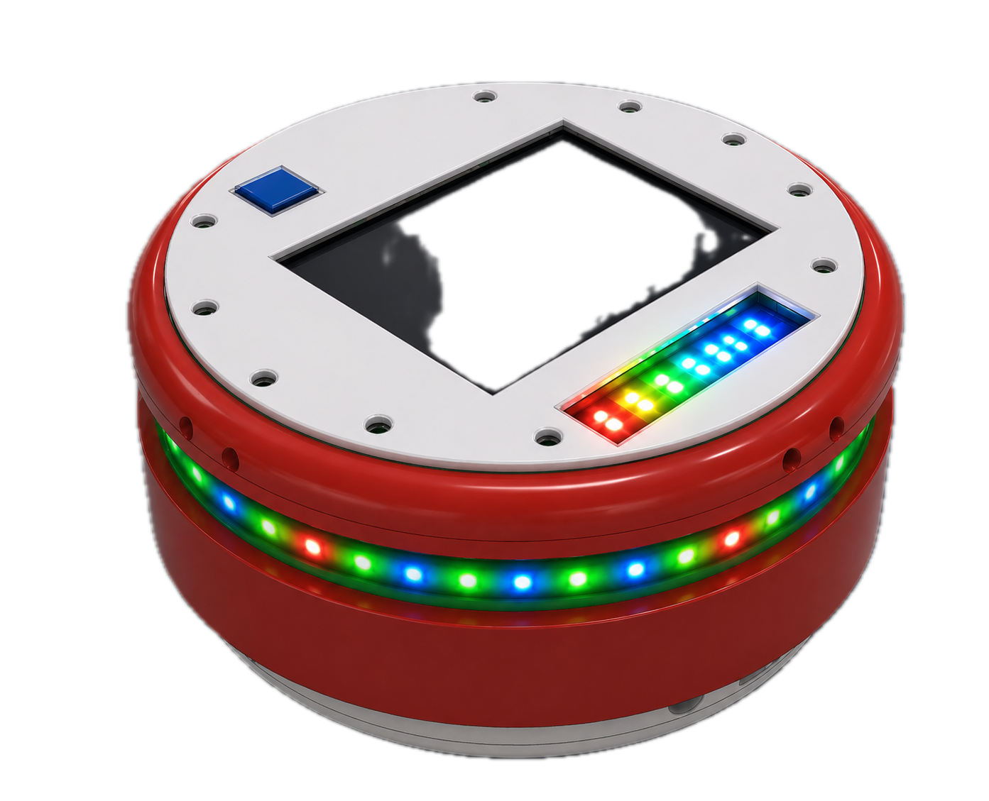 | 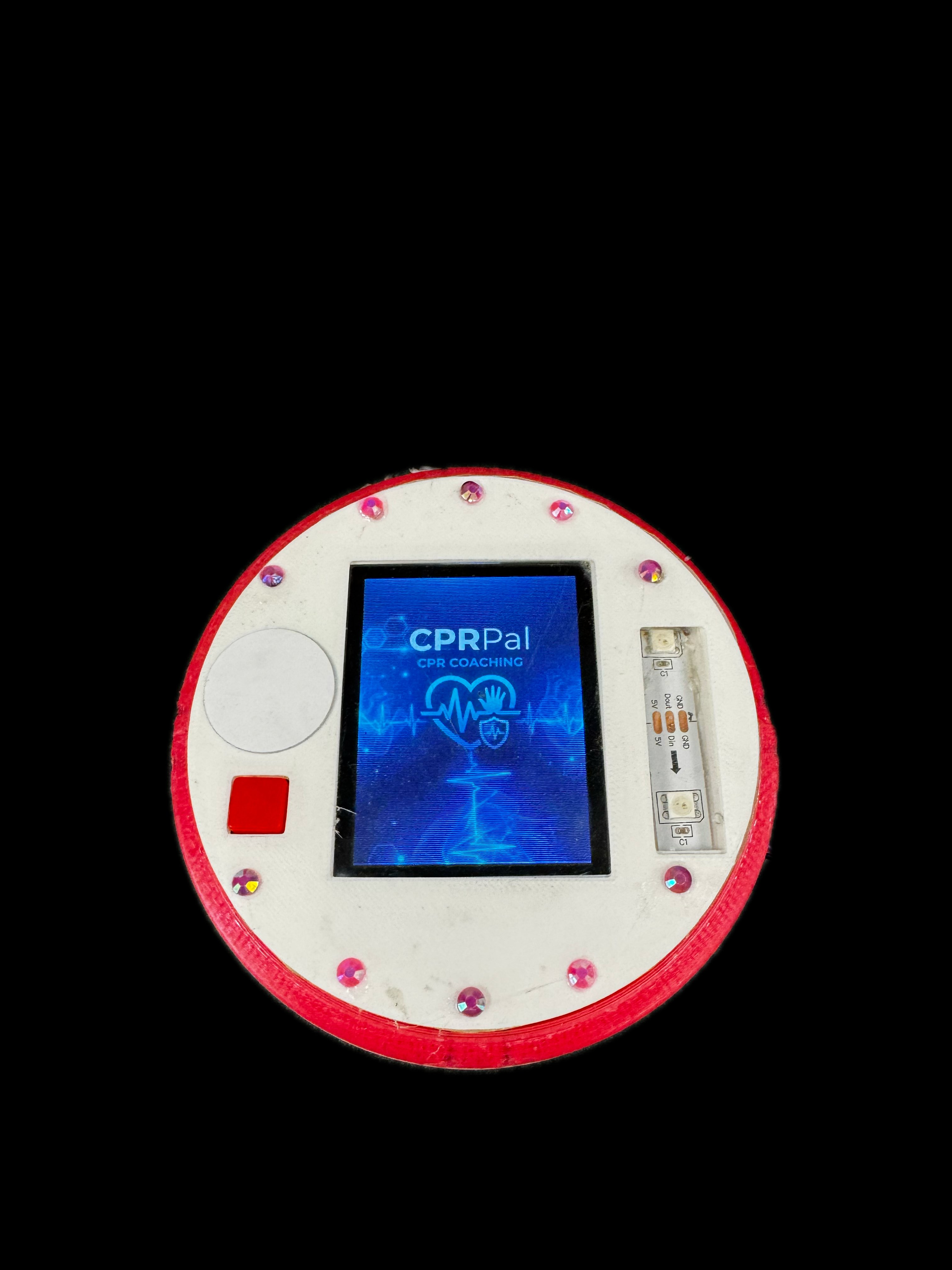 |
CPRPal/
├── 3DModel/
│   └── Mechanical enclosure and CAD files
│       - Top shell with lattice structure and LCD/button/LED cutouts
│       - Bottom shell with battery pocket, support beams, and hard stops
│       - Full assembly files for PLA 3D printing
│
├── ArduinoCode/
│   └── CPRPal.ino — Main ESP32 firmware (FreeRTOS-based)
│       - Sensor integration (HX711, BNO055, PPG)
│       - Real-time signal processing and CPM detection
│       - LED and display feedback systems
│       - Emergency and Training mode logic
│       - Power management and idle sleep
│       - HTTP cloud upload for training sessions
│
├── ArduinoWebsite/
│   └── Azure Static Web App source code
│       - Frontend dashboard (HTML/CSS/JS)
│       - Azure Function API endpoint
│       - Receives HTTP POST from ESP32
│       - Displays training session summary
│
├── PartsList/CPRPal uses a dual-core FreeRTOS architecture on the Arduino Nano ESP32-S3.
All time-critical sensor tasks run on Core 0 to prevent display rendering overhead from introducing jitter into sensor sampling.
| Task | Function | Sample Rate |
|---|---|---|
taskHX711 | Load cell reading, EMA filtering, CPM detection, idle detection | ~80 Hz |
taskIMU | BNO055 orientation reading, tilt computation, posture status | ~40 Hz |
taskPPG | PPG sampling, adaptive peak detection, BPM estimation | ~50 Hz |
taskBuzzer | 100 BPM metronome via LEDC PWM, rhythm LED strip sync | 100 BPM |
The Arduino loop() function runs on Core 1 and handles all output rendering:
All shared sensor variables use the g_ prefix, are declared volatile, and are protected by the FreeRTOS mutex xDataMutex. A second mutex xWireMutex serializes I2C bus access between taskIMU and any other bus user. This two-mutex architecture prevents data races while minimizing lock hold time.
| Component | Part | Purpose |
|---|---|---|
| Microcontroller | Arduino Nano ESP32-S3 | Main processing, Wi-Fi, dual-core FreeRTOS |
| Force Sensor | Half-bridge strain gauge load cell (120 lb) | Direct compression force measurement |
| Load Cell Amplifier | HX711 24-bit ADC | Amplifies and digitizes load cell signal at 80 SPS |
| IMU | Adafruit BNO055 9-DOF Fusion Breakout | Orientation, tilt detection, motion artifact rejection |
| Pulse Sensor | Pulse Sensor Amped (PPG) | Supplemental heartbeat detection |
| Display | Adafruit 2.8" ILI9341 TFT LCD | Real-time prompts and numeric status |
| LED Strips | Adafruit NeoPixel WS2812B (18 total) | Force bar (15 px) and rhythm metronome (3 px) |
| Buzzer | Piezo buzzer | 100 BPM audio metronome |
| Power Regulation | TPS63070 buck-boost converter x2 | Regulated 3.3V and 5V rails from 4xAA batteries |
| Reverse Protection | LM66200 ideal diode x2 | Prevents USB-to-battery reverse current |
| Storage | SanDisk 32GB microSD | Boot animation BMP frames |
| Battery | 4xAA alkaline | 10+ hours runtime at normal operating load |
| Enclosure | PLA 3D print | 4.7" x 4.7" x 2.4" puck housing |
| Pin | Peripheral | Function |
|---|---|---|
| GPIO2 | HX711 CLK | Load cell clock |
| GPIO3 | HX711 DOUT | Load cell data |
| GPIO4 | SD Card CS | microSD chip select |
| GPIO6 (D6) | Start Button | Mode selection (active low, internal pull-up) |
| GPIO9 | ILI9341 DC | TFT data/command select |
| GPIO10 | ILI9341 CS | TFT chip select |
| GPIO19 | Buzzer | LEDC PWM channel 0, 2 kHz |
| GPIO21 | PPG LED indicator | Heartbeat flash LED |
| GPIO23 | PPG Sensor | Analog ADC input |
| GPIO2 (LED_PIN) | NeoPixel force bar | 15-pixel WS2812B data |
| GPIO4 (RHYTHM) | NeoPixel rhythm strip | 3-pixel WS2812B data |
| A4 (SDA) | BNO055 SDA | I2C data, 400 kHz |
| A5 (SCL) | BNO055 SCL | I2C clock, 400 kHz |
| Wire Color | HX711 Pin | Function |
|---|---|---|
| RED | E+ | Excitation positive |
| BLACK | E- | Excitation negative |
| WHITE | A- | Signal negative (differential) |
| GREEN | A+ | Signal positive (differential) |
| YELLOW | GND | Common ground reference |
Two 1 kOhm resistors on the HX711 board complete the Wheatstone bridge by providing the two fixed-impedance legs of the half-bridge configuration.
CPRPal uses a custom panelized PCB fabricated by JLCPCB, separated into six press-fit sub-boards using mouse-bite breakaway tabs. Each sub-board can be removed and replaced independently without additional soldering.
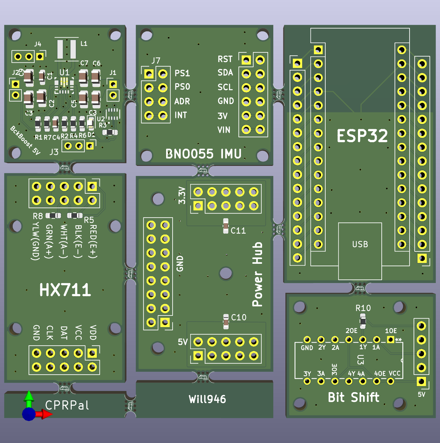
| Board | Key Components | Output |
|---|---|---|
| 3.3V BuckBoost | TPS63070, LM66200, 213k/365k feedback divider, decoupling caps, 1.5uH inductor | Regulated 3.3V rail |
| 5V BuckBoost | TPS63070, LM66200, alternate feedback divider, decoupling caps, 1.5uH inductor | Regulated 5V rail |
| Power Hub | Distribution headers, 10uF X5R decoupling caps x2 | Common power and ground plane |
| HX711 | HX711 IC, 1kOhm bridge resistors, DOUT/CLK headers | Load cell ADC interface |
| BNO055 IMU | BNO055 breakout, 10kOhm I2C pull-ups, 32.768kHz crystal | Euler angle outputs via I2C |
| ESP32 | Nano ESP32-S3 socket, USB passthrough | Main MCU |
| Bit Shift | Logic level shifter | 3.3V to 5V NeoPixel data translation |
| Reference | Component | Footprint |
|---|---|---|
| U1 | TPS63070 — Buck-boost converter | SOT-23-8 |
| U2 | LM66200 — Ideal diode controller | SOT-23-6 |
| L1 | 1.5 µH inductor | Inductor_SMD 4x4mm |
| R1, R2 | Feedback divider resistors (213k / 365k for 3.3V; alternate values for 5V) | 0402 |
| R3 | Current sense resistor | 0402 |
| R4, R6, R7 | Bias/compensation resistors | 0402 |
| C1–C6 | Decoupling and compensation capacitors | 0402 |
| C7 | Output bulk capacitor | 0805 |
| D1 | Schottky diode | SOD-123 |
| J1, J2, J3, J4 | Power input/output headers | PinHeader 1x02 2.54mm |
| Reference | Component | Footprint |
|---|---|---|
| C10, C11 | 10 µF X5R decoupling capacitors | 0805 |
| J (3.3V) | 3.3V distribution header | PinHeader 2x05 2.54mm |
| J (5V) | 5V distribution header | PinHeader 2x05 2.54mm |
| J (GND) | Ground distribution header | PinHeader 1x08 2.54mm |
| Reference | Component | Footprint |
|---|---|---|
| U1 | HX711 — 24-bit ADC | SOP-16 |
| R5, R8 | 1 kΩ Wheatstone bridge completion resistors | 0402 |
| J (VDD, VCC, DAT, CLK, GND) | MCU interface header | PinHeader 1x05 2.54mm |
| J (RED, BLK, WHT, GRN, YLW) | Load cell wire header | PinHeader 1x05 2.54mm |
| Reference | Component | Footprint |
|---|---|---|
| U1 | BNO055 — 9-DOF IMU | LGA-28 (custom) |
| X1 | 32.768 kHz crystal | Crystal SMD 3.2x1.5mm |
| R1, R2 | 10 kΩ I2C pull-up resistors | 0402 |
| J7 | Configuration header (PS0, PS1, ADR, INT) | PinHeader 1x04 2.54mm |
| J (RST, SDA, SCL, GND, 3V, VIN) | MCU interface header | PinHeader 1x06 2.54mm |
| Reference | Component | Footprint |
|---|---|---|
| U1 | Arduino Nano ESP32-S3 | Custom dual-row female socket, 2x15 2.54mm |
| J (USB) | USB-C passthrough cutout | USB-C receptacle footprint |
| J (left, right) | GPIO breakout headers | PinHeader 1x15 2.54mm x2 |
| Reference | Component | Footprint |
|---|---|---|
| U3 | 74AHCT125 — Quad level shifter | SOIC-14 |
| R10 | Pull-down resistor | 0402 |
| J (input) | 3.3V NeoPixel data input header | PinHeader 1x02 2.54mm |
| J (output) | 5V NeoPixel data output header | PinHeader 1x02 2.54mm |
| J (VCC, GND) | Power headers | PinHeader 1x02 2.54mm |
Two independent TPS63070 buck-boost converters are used instead of a single converter with an LDO post-regulator. This improves efficiency across the full 4xAA discharge range (approximately 6V fully charged to 4.8V near end of life), since the buck-boost topology maintains tight output regulation without the linear losses an LDO would introduce at shrinking headroom.
The firmware is a single Arduino sketch located in ArduinoCode/CPRPal.ino. It is written in C++ using the Arduino framework for ESP32 and relies on FreeRTOS task management, mutex-protected shared state, and the ESP32's LEDC hardware PWM peripheral for the buzzer metronome.
// Force feedback thresholds (lbs)
const float FORCE_THRESHOLD_LB      = 30.0f;   // Rising edge detection
const float FORCE_LOW_OK            = 75.0f;   // Below = TOO LIGHT (yellow)
const float FORCE_HIGH_OK           = 110.0f;  // Above = TOO STRONG (red)

// CPM thresholds
const float CPM_LOW_OK              = 100.0f;  // Below = TOO SLOW
const float CPM_HIGH_OK             = 120.0f;  // Above = TOO FAST
const unsigned long CPM_DEBOUNCE_MS = 180UL;   // Anti-bounce window
const int CPM_INTERVAL_COUNT        = 6;       // Rolling average window size

// Tilt feedback
const float TILT_WARN_DEG           = 8.0f;    // Above = ADJUST

// Timing
const unsigned long IDLE_TIMEOUT_MS     = 20000UL;  // 20s inactivity -> idle
const unsigned long TRAINING_SESSION_MS = 120000UL; // 2-minute session
const unsigned long TRAINING_SAMPLE_MS  = 3000UL;   // Sample every 3s
const unsigned long TRAINING_HOLD_MS    = 3000UL;   // Button hold -> Training

// Buzzer metronome
#define BUZZER_FREQ_HZ    2000  // 2 kHz tone
#define BUZZER_BEEP_MS    30    // On-time per beat in ms
#define BUZZER_PERIOD_MS 600 // Full period = 100 BPMThe calibration factor can be adjusted without reflashing firmware using the Serial Monitor at 115200 baud:
| Key | Action |
|---|---|
+ or a | Increase calibration factor by 10 |
- or z | Decrease calibration factor by 10 |
t or T | Tare the scale (zero current load) |
r or R | Reset session peak weight |
Raw load cell readings are smoothed before any threshold detection:
w_filtered[n] = 0.75 * w_filtered[n-1] + 0.25 * w_raw[n]Smoothing factor alpha = 0.25 was chosen empirically to balance noise rejection against compression onset detection latency.
CPM = 60000 / delta_t_msOn startup, 100 BNO055 orientation samples are captured (after 50 warm-up discards) and averaged as the resting baseline. All subsequent readings are deltas from this baseline so tilt feedback is relative to device placement on the patient, not absolute gravity direction.
On power-on the device performs the following sequence automatically:
Activated by a short press of the start button.
Activated by holding the button for 3 seconds.
| Channel | States | Meaning |
|---|---|---|
| LCD — CPM | WAITING / TOO SLOW / GOOD / TOO FAST | Compression rate guidance toward 100-120 CPM |
| LCD — Force | TOO LIGHT / GOOD / TOO STRONG | Compression depth guidance toward AHA target |
| LCD — Tilt | GOOD / ADJUST / LEAN | Posture and off-axis warning |
| LCD — PPG | BPM value / Heartbeat detect / Missing heartbeat | Supplemental pulse status |
| NeoPixel bar | Yellow / Green / Red | Visual force classification |
| Buzzer + rhythm LEDs | 100 BPM beep + amber flash | Compression pacing metronome |
| Force Range | LED Color | LCD Status | Meaning |
|---|---|---|---|
| < 5 lb | Off | — | No significant contact |
| 5–75 lb | Yellow | TOO LIGHT | Insufficient compression force |
| 75–110 lb | Green | GOOD | Target depth range |
| > 110 lb | Red | TOO STRONG | Excessive force |
| CPM Range | LCD Status |
|---|---|
| < 1 | WAITING |
| 1–99 | TOO SLOW |
| 100–120 | GOOD |
| > 120 | TOO FAST |
| Tilt Magnitude | LCD Status |
|---|---|
| < 5 degrees | GOOD |
| 5–10 degrees | ADJUST |
| > 10 degrees | LEAN |
| Rail | Powered Components |
|---|---|
| 3.3V | ESP32-S3, BNO055 IMU, PPG sensor, piezo buzzer |
| 5V | ILI9341 LCD, NeoPixel strips (18 px total), HX711 amplifier |
| Operating Mode | Current Draw | Notes |
|---|---|---|
| Peak startup | ~235 mA | Boot animation with full brightness LEDs and LCD |
| Normal (Emergency Mode) | ~155 mA | Colored LEDs at 40/255, dim LCD, all sensors active |
| Idle (tasks suspended) | ~95 mA | LCD dim showing idle screen, ESP32 running, all else off |
| Training Mode | ~195 mA | Normal + 40 mA Wi-Fi radio, no idle mode |
At 155 mA normal draw with a 2700 mAh 4xAA pack, theoretical runtime is approximately 17 hours. Measured battery life exceeded 10 hours under mixed-use testing.
https://gentle-stone-0c20e761e.6.azurestaticapps.net/The dashboard is a static web application hosted on Microsoft Azure Static Web Apps using the free tier only. No charges are incurred.
ESP32 collects sensor data every 3s during Training Mode session
  -> Averages computed at 2-minute session end
  -> JSON payload manually serialized (no external library)
  -> HTTP POST to Azure Function API endpoint
  -> Azure processes and stores payload
-> Dashboard displays session summary{
"deviceId": "nano-esp32-test",
"timestamp": "123456789",
"mode": "TRAINING",
"sessionType": "summary",
"ppg": 1800,
"imuY": 2.5,
"imuZ": -1.2,
"compressionRate": 110,
"compressionDepth": 85.3,
"recoil": 1,
"status": "Good compressions",
"sampleCount": 40,
"sessionDurationMs": 120000
}| Condition | Status Field Value |
|---|---|
| Rate > 125 CPM or depth > 6.2 lb | "Bad: too fast/deep" |
| Rate < 100 CPM or depth < 5.0 lb or recoil == 0 | "Warn: shallow/recoil" |
| All within range | "Good compressions" |
If Wi-Fi is unavailable when Training Mode is entered:
esp32 by Espressif SystemsOpen Arduino IDE and go to Sketch -> Include Library -> Manage Libraries. Search for and install each of the following:
| Library | Author |
|---|---|
| Adafruit BNO055 | Adafruit |
| Adafruit BusIO | Adafruit |
| Adafruit EPD | Adafruit |
| Adafruit FT6206 Library | Adafruit |
| Adafruit GFX Library | Adafruit |
| Adafruit HX8357 Library | Adafruit |
| Adafruit ILI9341 | Adafruit |
| Adafruit ImageReader Library | Adafruit |
| Adafruit NeoMatrix | Adafruit |
| Adafruit NeoPixel | Adafruit |
| Adafruit seesaw Library | Adafruit |
| Adafruit SH110X | Adafruit |
| Adafruit SPIFlash | Adafruit |
| Adafruit SSD1331 OLED Driver Library for Arduino | Adafruit |
| Adafruit SSD1351 library | Adafruit |
| Adafruit ST7735 and ST7789 Library | Adafruit |
| Adafruit STMPE610 | Adafruit |
| Adafruit TouchScreen | Adafruit |
| Adafruit TSC2007 | Adafruit |
| Adafruit Unified Sensor | Adafruit |
| HX711 | bogde |
| PulseSensor Playground | World Famous Electronics |
| SdFat - Adafruit Fork | Adafruit |
WiFi and HTTPClient are included with the ESP32 Arduino core and do not require separate installation.
The boot animation requires 8 BMP image files placed in the root of a FAT32-formatted microSD card. Name the files exactly as follows:
/Step0.bmp
/Step1.bmp
/Step2.bmp
/Step3.bmp
/Step4.bmp
/Step5.bmp
/Step6.bmp
/Step7.bmp
Each image should be a 24-bit BMP at 240x320 pixels to match the ILI9341 display resolution. If the SD card fails to mount, the firmware will halt and display an error on the TFT screen.
Open ArduinoCode/CPRPal.ino and locate the following lines near the top of the file:
const char* WIFI_SSID     = "YOUR_SSID_HERE";
const char* WIFI_PASSWORD = "YOUR_PASSWORD_HERE";
Replace with your Wi-Fi network credentials. Wi-Fi is only used during Training Mode. Emergency Mode runs fully offline regardless of these settings.
Note: The ESP32 posts directly to the Azure cloud endpoint over any internet-connected Wi-Fi network. The viewing device does not need to be on the same network as the ESP32.
In Arduino IDE:
Click Upload in Arduino IDE. Open the Serial Monitor at 115200 baud to view boot diagnostics, reset reason history, sensor readings, and calibration output.
+ and - keys in Serial Monitor to adjust calibration factor until the displayed value matches the known weightcalibration_factor in the sketch to save it permanently| Library | Purpose in CPRPal |
|---|---|
| Adafruit BNO055 | BNO055 IMU driver and Euler angle output |
| Adafruit BusIO | I2C/SPI abstraction layer required by Adafruit sensor libraries |
| Adafruit GFX Library | Core graphics primitives for TFT display rendering |
| Adafruit ILI9341 | ILI9341 TFT display driver |
| Adafruit ImageReader Library | BMP image loading from SD card for boot animation |
| Adafruit NeoPixel | WS2812B addressable LED control for force bar and rhythm strip |
| Adafruit NeoMatrix | NeoPixel matrix support (dependency) |
| Adafruit Unified Sensor | Unified sensor abstraction required by BNO055 driver |
| Adafruit SPIFlash | SPI flash support (alternative storage backend) |
| SdFat - Adafruit Fork | SD card FAT filesystem for microSD BMP loading |
| Adafruit EPD | E-paper display support (dependency) |
| Adafruit FT6206 Library | Capacitive touchscreen support (dependency) |
| Adafruit HX8357 Library | HX8357 display driver (dependency) |
| Adafruit seesaw Library | Adafruit seesaw breakout support (dependency) |
| Adafruit SH110X | OLED display driver (dependency) |
| Adafruit SSD1331 OLED Driver | SSD1331 OLED support (dependency) |
| Adafruit SSD1351 library | SSD1351 OLED support (dependency) |
| Adafruit ST7735 and ST7789 Library | ST77xx display drivers (dependency) |
| Adafruit STMPE610 | Touch controller support (dependency) |
| Adafruit TouchScreen | Resistive touchscreen support (dependency) |
| Adafruit TSC2007 | Touch controller support (dependency) |
| HX711 by bogde | HX711 load cell amplifier driver |
| PulseSensor Playground | PPG pulse sensor signal processing |
CPRPal is a prototype device developed for educational purposes. It is not a certified medical device. Always call emergency services first in a cardiac emergency.
| Qty | Value | Footprint | References |
|---|---|---|---|
| 18 | MountingHole | MountingHole:MountingHole_2.2mm_M2 | H1, H2, H3, H4, H5, H6, H7, H10, H11, H12, H13, H14, H15, H16, H17, H19 +2 |
| 10 | VAL** | MouseBite:mouse-bite-2mm-4mm | mouse-bite-2mm-4mm, mouse-bite-2mm-4mm, mouse-bite-2mm-4mm, mouse-bite-2mm-4mm, mouse-bite-2mm-4mm, mouse-bite-2mm-4mm, mouse-bite-2mm-4mm, mouse-bite-2mm-4mm, mouse-bite-2mm-4mm, mouse-bite-2mm-4mm |
| 4 | 10uF | Capacitor_SMD:C_0805_2012Metric_Pad1.18x1.45mm_HandSolder | C2, C3, C5, C9 |
| 4 | Conn_02x05_Odd_Even | Connector_PinHeader_2.54mm:PinHeader_2x05_P2.54mm_Vertical | J6, J9, J13, J14 |
| 3 | 22uF | Capacitor_SMD:C_0805_2012Metric_Pad1.18x1.45mm_HandSolder | C6, C7, C8 |
| 2 | 0.1uF | Capacitor_SMD:C_0603_1608Metric_Pad1.08x0.95mm_HandSolder | C1, C4 |
| 2 | 100nF | Capacitor_SMD:C_0603_1608Metric_Pad1.08x0.95mm_HandSolder | C10, C11 |
| 2 | 10k | Resistor_SMD:R_0603_1608Metric_Pad0.98x0.95mm_HandSolder | R1, R7 |
| 2 | 1K | Resistor_SMD:R_0603_1608Metric_Pad0.98x0.95mm_HandSolder | R5, R8 |
| 2 | Conn_01x02_Pin | Connector_PinHeader_2.00mm:PinHeader_1x02_P2.00mm_Vertical | J1, J2 |
| 2 | Conn_01x03_Pin | Connector_PinHeader_2.00mm:PinHeader_1x03_P2.00mm_Vertical | J3, J4 |
| 2 | Conn_01x15_Pin | Connector_PinHeader_2.54mm:PinHeader_1x15_P2.54mm_Vertical | J10, J11 |
| 1 | 1.5uH | Inductor_SMD:L_Coilcraft_XxL4020 | L1 |
| 1 | 10K | Resistor_SMD:R_0603_1608Metric_Pad0.98x0.95mm_HandSolder | R10 |
| 1 | 1k | Resistor_SMD:R_0603_1608Metric_Pad0.98x0.95mm_HandSolder | R6 |
| 1 | 365k | Resistor_SMD:R_0603_1608Metric_Pad0.98x0.95mm_HandSolder | R4 |
| 1 | 50k | Resistor_SMD:R_0603_1608Metric_Pad0.98x0.95mm_HandSolder | R3 |
| 1 | 68.1k | Resistor_SMD:R_0603_1608Metric_Pad0.98x0.95mm_HandSolder | R2 |
| 1 | Arduino_Nano_ESP32 | Module:Arduino_Nano | A1 |
| 1 | Conn_01x05_Pin | Connector_PinHeader_2.54mm:PinHeader_1x05_P2.54mm_Vertical | J5 |
| 1 | Conn_02x04_Odd_Even | Connector_PinHeader_2.54mm:PinHeader_2x04_P2.54mm_Vertical | J7 |
| 1 | Conn_02x06_Odd_Even | Connector_PinHeader_2.54mm:PinHeader_2x06_P2.54mm_Vertical | J8 |
| 1 | Conn_02x08_Odd_Even | Connector_PinHeader_2.54mm:PinHeader_2x08_P2.54mm_Vertical | J12 |
| 1 | LM66200DRLR | LM66200DRLR:SOT-5X3_DRL_TEX-L | U2 |
| 1 | RED | LED_SMD:LED_0603_1608Metric | D1 |
| 1 | SN74AHCT125N | SN74AHCT125N:N14 | U3 |
| 1 | TPS63070 | TPS63070RNMR:RNM0015A | U1 |
It measures 78.8 × 71.9 mm and has 2 copper layers, 1.6 mm thick.
68 parts, built around the SN74AHCT125N and TPS63070RNM. The full list of its parts is on this page, with links to each part's symbol and footprint where PCBKit's library has them.
From the Will946/CPRPal repository on GitHub, at the commit this page was made from: the board is PCB/EE496.kicad_pcb and its schematic PCB/EE496.kicad_sch. PCBKit opens the board in the browser, with nothing to install.
Its repository publishes it under the MIT licence: you may reuse it on that licence's terms (keep the author's notice, and for a copyleft licence share your changes alike).
CDFER/NIMRS-21Pin-Decoder
An open source 21-Pin DCC Decoder for model trains


H3wastooshort/BikeUSBv2
Charge your Phone off of your Bike while adapting charging power to available power / riding speed.


takuhoTech/LagopusSystem-2024
Avionics for Human-Powered Aircraft (Japan International Birdman Rally 2024)

TobleMiner/catear-pcb
This repo contains the PCB for the Nekomimi project of @BenBE . It will be used to illuminate 3D printed catears.