4 layers44.3 × 39 mm
Gmax4002-breakout
will127534/gmax4002-breakout
A basic minimum GMAX4002 breakout board for Raspberry Pi
142 parts12MIT

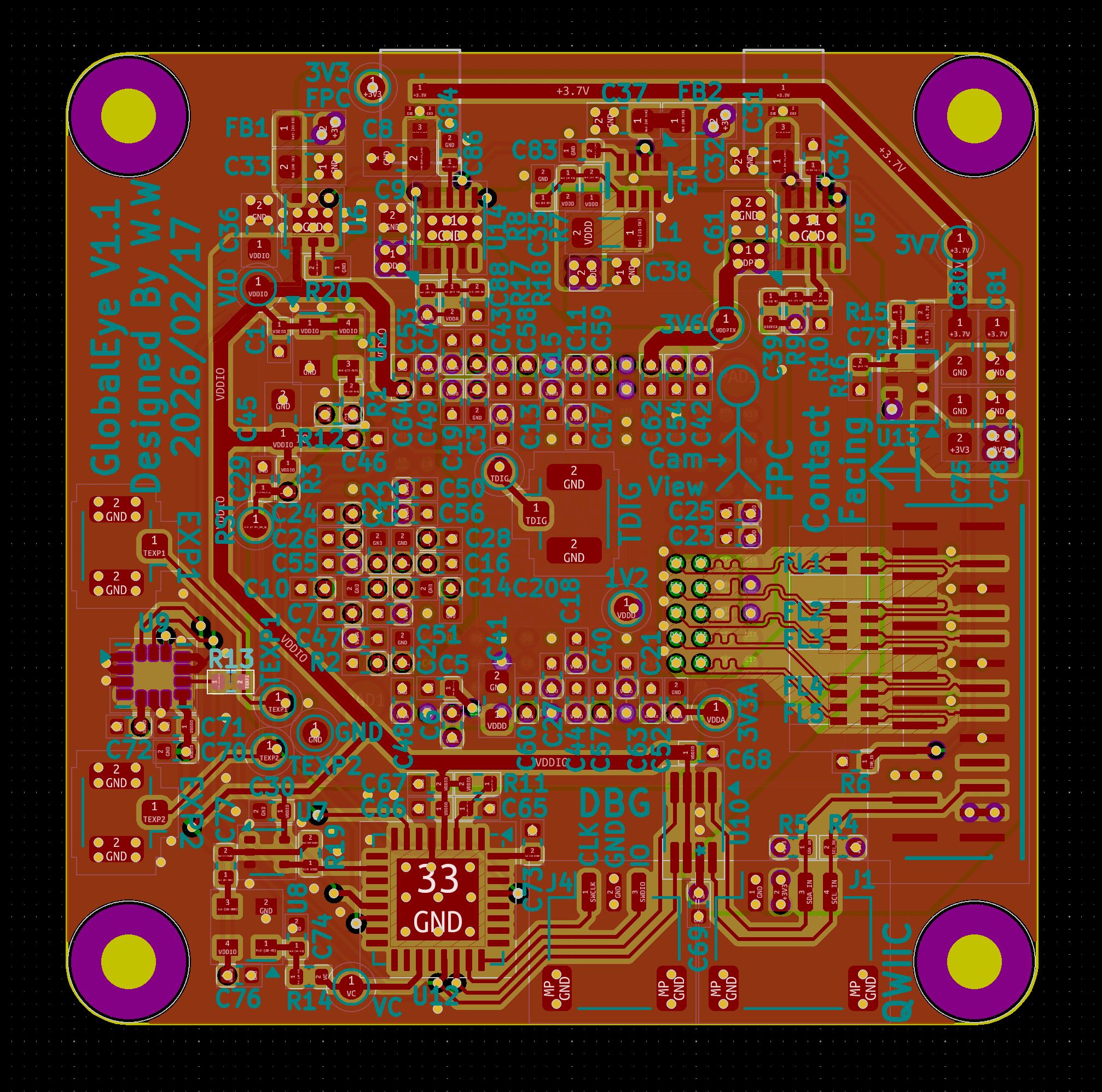
 will127534/GlobalEye31
A simple camera board using GMAX3412 1" 4K@30fps global shutter sensor
GlobalEye is an open-source printed circuit board by will127534, from the will127534/GlobalEye repository on GitHub, published under the MIT licence. It is a 4-layer board of 39 × 39 mm with 148 parts on 133 nets, routed with 558 tracks and 369 vias.
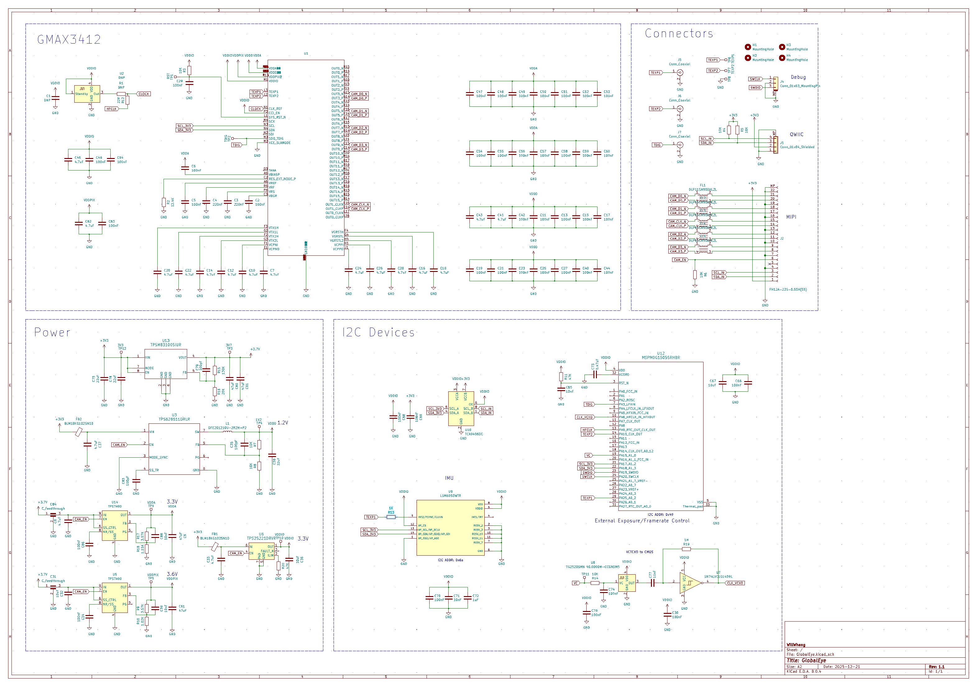
It is built around the TPSM83100SIUR, ICM-42688-P and SN74LVC1G14DRL, with the TCA9406DCT, DLP11SN900HL2L and DFE201210U-2R2M=P2 among its other parts. Its parts include 85 capacitors, 20 resistors, 12 ICs, 6 connectors and 1 inductor.


A basic minimum GMAX3412 (1" / 4096×3072 / Global Shutter) board for Raspberry Pi.
In general this is a simple breakout board for the GMAX3412 sensor — see the driver repo here.
The sensor itself is quite interesting: it needs a trigger pulse to start a new frame, and it can’t generate that pulse by itself. Because of that, this board includes a MSPM0G1505 MCU to generate the signal (sweet 32bit PWM output) and listen for commands over I2C.
The MCU firmware and the Python script to talk to it live under software/.
But if you are planning to send the clock/trigger via other means, you can ignore that and use the U.FL connector to feed signals in.
The driver is set up as external exposure:
Gerbers/ — manufacturing filesbom/ — BOM / parts listsoftware/ — MSPM0 firmware + Python I2C control scriptdatasheet/ — datasheet backup copySee it in action here: Youtube.
The board is tested with Raspberry Pi 5.
The trigger signal looks like this:
Yellow is the TEXP, and blue one is the TDIG output from the sensor showing "Frame Overhead Time".
 ## Datasheet
It is not every day you see a detailed datasheet directly from the manufacture appared on the top search result:
https://gpixel.com/public/uploads/admin/file/pdf-7917552d763a512ce4860ce10e70934f.pdf
…but I also keep a backup under the datasheet/ folder.
Current issue I would say is that RPI will shows different FPS reading then the setting because RPI/CAM/MCU are all on different clock, and it is hard to have fine tuning to the timers (the current setup is using 16bit timer), that is why I have VCTCXO on board providing the clock to both MSPM0 and GMAX3412 so the clock can be fine tuned with software. But I left the resistor jumper and the pad that you could instead simplified it a bit to just a simple OSC for GMAX3412 and MCU can use it's internal 80Mhz clock.
Final note is that the power consumption is a step higher then normal rolling shutter sensors, so the board might be a bit warm when operating.
| Qty | Value | Footprint | References |
|---|---|---|---|
| 43 | 100nF | Capacitor_SMD:C_0402_1005Metric | C1, C2, C11, C13, C15, C17, C19, C21, C23, C25, C27, C29, C30, C34, C40, C42 +27 |
| 13 | 4.7uF | Capacitor_SMD:C_0402_1005Metric | C7, C10, C12, C14, C16, C18, C20, C22, C24, C26, C28, C43, C62 |
| 7 | 10K | Resistor_SMD:R_0402_1005Metric | R3, R4, R5, R6, R7, R8, R14 |
| 5 | 10nF | Capacitor_SMD:C_0402_1005Metric | C39, C65, C71, C77, C88 |
| 5 | 4.7uF | Capacitor_SMD:C_0603_1608Metric | C8, C33, C37, C41, C45 |
| 5 | DLP11SN900HL2L | footprints:DLP11SA350HL2B | FL1, FL2, FL3, FL4, FL5 |
| 4 | MountingHole | MountingHole:MountingHole_2.2mm_M2 | H1, H2, H3, H4 |
| 3 | 100pF | Capacitor_SMD:C_0402_1005Metric | C35, C79, C83 |
| 3 | 22uF | Capacitor_SMD:C_0603_1608Metric | C38, C75, C78 |
| 3 | 47uF | Capacitor_SMD:C_0603_1608Metric | C9, C80, C81 |
| 3 | Conn_Coaxial | Connector_Coaxial:U.FL_Hirose_U.FL-R-SMT-1_Vertical | J5, J6, J7 |
| 3 | VDDA | TestPoint:TestPoint_Pad_D1.0mm | TP8, TP9, TP11 |
| 2 | 1.02K | Resistor_SMD:R_0402_1005Metric | R10, R18 |
| 2 | 10R | Resistor_SMD:R_0402_1005Metric | R12, R13 |
| 2 | 10uF | Capacitor_SMD:C_0603_1608Metric | C32, C36 |
| 2 | 220nF | Capacitor_SMD:C_0402_1005Metric | C3, C4 |
| 2 | 3.57K | Resistor_SMD:R_0402_1005Metric | R9, R17 |
| 2 | 47K | Resistor_SMD:R_0402_1005Metric | R11, R20 |
| 2 | BLM18KG102SN1D | Inductor_SMD:L_0603_1608Metric | FB1, FB2 |
| 2 | C_Feedthrough | footprints:NFM18CC101R1C3D | C31, C84 |
| 2 | TPS7A90 | Package_DFN_QFN:Texas_S-PDSO-N10_EP1.2x2mm | U5, U14 |
| 1 | clipboard:5ff0eec8-df25-4170-9165-fee4a858008b | ||
| 1 | 0.47uF | Capacitor_SMD:C_0402_1005Metric | C73 |
| 1 | 10uF | Capacitor_SMD:C_0402_1005Metric | C67 |
| 1 | 12.4K | Resistor_SMD:R_0402_1005Metric | R2 |
| 1 | 1M | Resistor_SMD:R_0402_1005Metric | R19 |
| 1 | 1V2 | TestPoint:TestPoint_Pad_D1.0mm | TP4 |
| 1 | 1uF | Capacitor_SMD:C_0402_1005Metric | C72 |
| 1 | 22R | Resistor_SMD:R_0402_1005Metric | R1 |
| 1 | 3V3 | TestPoint:TestPoint_Pad_D1.0mm | TP12 |
| 1 | 3V7 | TestPoint:TestPoint_Pad_D1.0mm | TP3 |
| 1 | 47uF | Capacitor_SMD:C_0805_2012Metric | C61 |
| 1 | 562K | Resistor_SMD:R_0402_1005Metric | R15 |
| 1 | 91K | Resistor_SMD:R_0402_1005Metric | R16 |
| 1 | Conn_01x03_MountingPin | Connector_JST:JST_SH_SM03B-SRSS-TB_1x03-1MP_P1.00mm_Horizontal | J4 |
| 1 | Conn_01x04_Shielded | Connector_JST:JST_SH_SM04B-SRSS-TB_1x04-1MP_P1.00mm_Horizontal | J1 |
| 1 | DFE201210U-2R2M=P2 | Inductor_SMD:L_0805_2012Metric | L1 |
| 1 | ECS-2520MV-400-DN-TR | Oscillator:Oscillator_SMD_Abracon_ASDMB-4Pin_2.5x2.0mm | U2 |
| 1 | FH12A-22S-0.5SH(55) | footprints:TF3822S05SV830 | J2 |
| 1 | FT5HV | Oscillator:Oscillator_SMD_Abracon_ASDMB-4Pin_2.5x2.0mm | U8 |
| 1 | ICM-42688-P | footprints:PQFN50P300X250X97-14N | U9 |
| 1 | MSPM0G1505SRHBR | Package_DFN_QFN:QFN-32-1EP_5x5mm_P0.5mm_EP3.3x3.3mm | U12 |
| 1 | RST | TestPoint:TestPoint_Pad_D1.0mm | TP1 |
| 1 | SN74LVC1G14DRL | Package_TO_SOT_SMD:SOT-553 | U7 |
| 1 | TCA9406DC | Package_SO:VSSOP-8_2.3x2mm_P0.5mm | U10 |
| 1 | TDIG | TestPoint:TestPoint_Pad_D1.0mm | TP2 |
| 1 | TEXP1 | TestPoint:TestPoint_Pad_D1.0mm | TP6 |
| 1 | TEXP2 | TestPoint:TestPoint_Pad_D1.0mm | TP7 |
| 1 | TPS25221DRVR | Package_SON:WSON-6-1EP_2x2mm_P0.65mm_EP1x1.6mm | U6 |
| 1 | TPS628511DRLR | footprints:DRL0008A-MFG | U3 |
| 1 | TPSM83100SIUR | footprints:MICROSIP8_SIU_TEX-L | U13 |
| 1 | VDDIO | TestPoint:TestPoint_Pad_D1.0mm | TP10 |
| 1 | VDDPIX | TestPoint:TestPoint_Pad_D1.0mm | TP5 |
| 1 | ~ | GMAX3412:LGA-255_17x15_23.0x19.4mm | U1 |
It measures 39 × 39 mm and has 4 copper layers, 1.6 mm thick.
148 parts, built around the TPSM83100SIUR, ICM-42688-P, SN74LVC1G14DRL and TCA9406DCT. The full list of its parts is on this page, with links to each part's symbol and footprint where PCBKit's library has them.
From the will127534/GlobalEye repository on GitHub, at the commit this page was made from: the board is GlobalEye.kicad_pcb and its schematic GlobalEye.kicad_sch. PCBKit opens the board in the browser, with nothing to install.
Its repository publishes it under the MIT licence: you may reuse it on that licence's terms (keep the author's notice, and for a copyleft licence share your changes alike).
will127534/gmax4002-breakout
A basic minimum GMAX4002 breakout board for Raspberry Pi

will127534/OneInchEye
A One Inch CMOS sensor (IMX283) camera board designed for Raspberry Pi

will127534/ShutterEye
A simple camera board using SC910GS 1" 4K@30fps global shutter sensor

BlueJayRacing/22xt_kicad
As a summary, you should be using KiCad Version 9.0. All project will be modular, and you should be storing all your step files, symbols, & footprints within the created folders.


