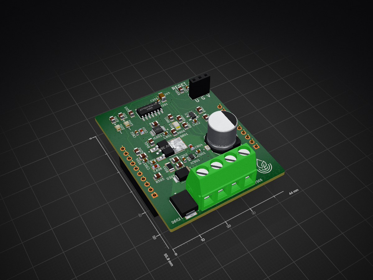
MQTT Module Pump Controller
This Module is in testing and not fully tested.
Module for the MQTT Modular Controller Board. Controls and powers a single small 12 V pump.
Features
- ATtiny1614 microcontroller
- I²C communication with motherboard (SDA/SCL)
- N-channel MOSFET + LM5060 high-side driver for pump control
- Overvoltage, undervoltage, and overcurrent protection
- Flyback diode, TVS, and filtering on pump output
- Green LED (pump running) and yellow LED (fault)
- 3-pin UPDI programming interface
- Adjustable passives for different pumps
- Maximum continuous pump current: 5 A
Architecture
Core Components
- Microcontroller: ATtiny1614
- Pump Driver: N-channel MOSFET paired with LM5060
- Maximum Pump Current: 5 A continuous
- Programming: 3-pin UPDI on PA0 (default fuse configuration: RSTPINCFG in FUSE.SYSCFG0 = 0x1)
Protection (LM5060)
- Overvoltage: Triggers at 15.6 V (rising), releases at 13.7 V (falling)
- Undervoltage: Triggers at 9.3 V (falling), releases at 10.5 V (rising)
- Overcurrent: Fault threshold ~5.69 A
- Timing:
- Startup threshold: ~157 ms
- Transition threshold: ~72 ms
- Overcurrent threshold: ~85 ms
Output Protection
- Flyback diode across pump screw terminals
- TVS diode on output
- Filtering and smoothing capacitors
- 0 Ω resistor on output line (for testing / future provision)
Pin Mapping (ATtiny1614)
| Function | Pin |
|---|
| UPDI | PA0 |
| SDA (I²C) | PA1 |
| SCL (I²C) | PA2 |
| Pump warning LED | PA4 |
| Pump running LED | PA5 |
| Motherboard GPIO | PA6 |
| Motherboard SNS | PA7 |
Communication
- I²C (SDA/SCL) to motherboard
- Motherboard sense (SNS) and general-purpose modular pin connected as listed above
Indicators
- Green LED: Pump running
- Yellow LED: Fault condition
Setup and Build
Firmware: Not yet implemented (TBA).
Programming:
- Use 3-pin UPDI interface on PA0
- Default fuse settings support UPDI (no change required)
Hardware Notes:
- Capacitors and resistors may be adjusted for different pumps
- Pump must not exceed 5 A continuous current on current configuration
- Conforms to the modular controller board 2x10 header interface
Repository Contents
- KiCad schematic and PCB files
- Project configuration
- Backups folder
- Outputs folder
License
This documentation is part of the MQTT-Module-PumpController project and is licensed under the CERN Open Hardware Licence Version 2 - Permissive (CERN-OHL-P-2.0).
You may redistribute and modify this documentation under the terms of the CERN-OHL-P-2.0.
This documentation is distributed WITHOUT ANY EXPRESS OR IMPLIED WARRANTY, INCLUDING OF MERCHANTABILITY, SATISFACTORY QUALITY AND FITNESS FOR A PARTICULAR PURPOSE. See the CERN-OHL-P-2.0 for applicable conditions.