2 layers230 × 85 mm
Le chiff ble hotswap
MangoIV/le_chiff_ble
A drop-in replacement-PCB for the beautiful le_chiffre
117 parts52GPL-3.0

 weteor/Unispliff3
34 key col stagger keyboard w/ encoder.
Unispliff is an open-source printed circuit board by weteor, from the weteor/Unispliff repository on GitHub, published under the CERN-OHL-P-2.0 licence. It is a 2-layer board of 196.1 × 87.8 mm with 99 parts on 79 nets, routed with 852 tracks and 168 vias.
It is built around the DW01A, FS8205 and TP4056, with the AO3401A, ASMD1206-150 and PRTR5V0U2X among its other parts. Its parts include 36 diodes, 36 switches, 10 capacitors, 6 resistors and 5 ICs.


34 key col stagger keyboad w/ encoder
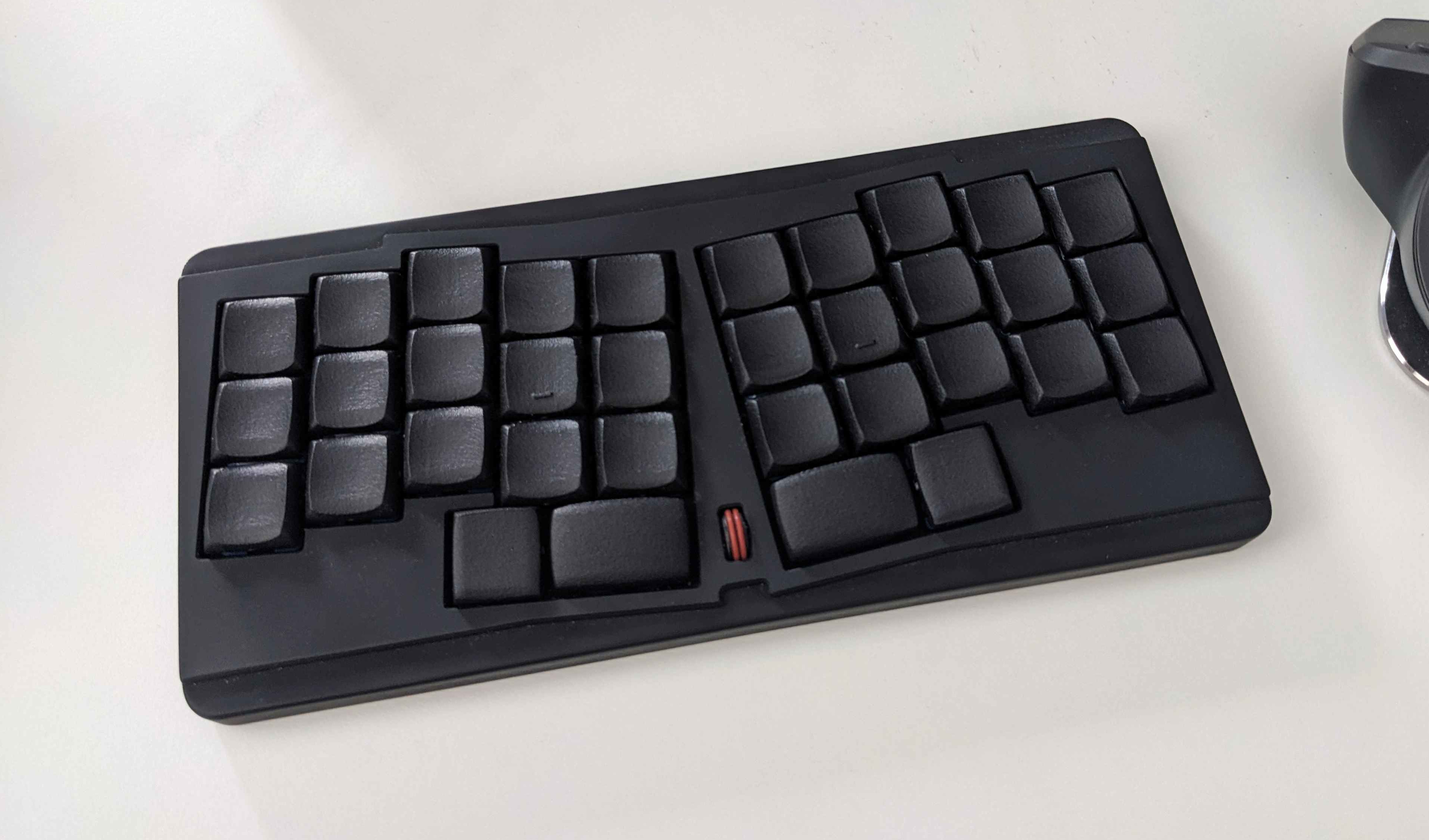
All production files you need to build your own board can be found here.
I've had my case printed in resin, nylon or similar should work fine too. FDM might be a bit more challenging because of the stepped top, your milage may vary.
I've provided some files for the encoder wheel, the design without groove can be used as is, the other ones user some silicone gaskets, you my have to look for some that fit. The 1.7 files are with a smaller diameter for the rod that is pressed in the encoder. I would advise to print both variants and see which one fits better.
Apart from the pcb and printed parts you need:
First flash a bootloader onto the controller. I've used the Adafruit nRf32 Bootloader. Firmware for ZMK can be found here. I've build local. If you need a Github workflow you will have to modify it yourself.
Everything in this repository is free to use however you might see fit. If you want to support me and my projects, please consider linking back to this repository if you build/change/use anything.
If you would like to send me a tip, you could do it here (Please don't feel like you have to).
| Qty | Value | Footprint | References |
|---|---|---|---|
| 34 | D_Small | weteor:D_SOD-123 | D1, D2, D10, D11, D12, D13, D14, D15, D16, D17, D18, D19, D20, D21, D22, D23 +18 |
| 32 | SW_Push_45deg | weteor:ChocV1_V2_Hotswap | SW1, SW2, SW11, SW12, SW13, SW14, SW15, SW16, SW17, SW19, SW20, SW21, SW23, SW24, SW25, SW26 +16 |
| 3 | 100n | Capacitor_SMD:C_0603_1608Metric | C4, C5, C6 |
| 2 | 10uF | Capacitor_SMD:C_0603_1608Metric | C1, C2 |
| 2 | 15pF | Capacitor_SMD:C_0603_1608Metric | C7, C8 |
| 2 | 1uF | Capacitor_SMD:C_0603_1608Metric | C9, C10 |
| 2 | 5k1 | Resistor_SMD:R_0603_1608Metric | R6, R7 |
| 2 | SW_Push_45deg | weteor:ChocV1_V2_Hotswap_1.5u | SW18, SW22 |
| 1 | 0.1uF | Capacitor_SMD:C_0603_1608Metric | C3 |
| 1 | 100R | Resistor_SMD:R_0603_1608Metric | R4 |
| 1 | 1k | Resistor_SMD:R_0603_1608Metric | R5 |
| 1 | 1k5 | Resistor_SMD:R_0603_1608Metric | R1 |
| 1 | 5k | Resistor_SMD:R_0603_1608Metric | R3 |
| 1 | AO3401A | Package_TO_SOT_SMD:SOT-23 | Q1 |
| 1 | ASMD1206-150 | Fuse:Fuse_1206_3216Metric | F1 |
| 1 | Battery_Cell | weteor:battery_pads | BT1 |
| 1 | Crystal_Small | Crystal:Crystal_SMD_3215-2Pin_3.2x1.5mm | Y1 |
| 1 | DW01A | Package_TO_SOT_SMD:SOT-23-6 | U3 |
| 1 | D_Schottky_Small | Diode_SMD:D_SOD-323_HandSoldering | D7 |
| 1 | FS8205 | Package_TO_SOT_SMD:SOT-23-6 | U4 |
| 1 | PRTR5V0U2X | Package_TO_SOT_SMD:SOT-143 | D36 |
| 1 | RotaryEncoder | weteor:EC05E1220203 | SW36 |
| 1 | SWD_Ext | Connector_PinHeader_2.54mm:PinHeader_1x04_P2.54mm_Vertical | J1 |
| 1 | SW_RESET | Button_Switch_SMD:SW_SPST_TL3342 | SW10 |
| 1 | TP4056 | weteor:TP4056_SOP-8-PP | U2 |
| 1 | USB_C_Receptacle_USB2.0_16P | weteor:USB-C-12-Pin-MidMount | J2 |
| 1 | XC6206PxxxMR | Package_TO_SOT_SMD:SOT-23 | U1 |
| 1 | e73-2gm08s1c-no-underside | mcu:e73-2g4m08s1c-no-underside | U6 |
It measures 196.1 × 87.8 mm and has 2 copper layers, 1.6 mm thick.
99 parts, built around the DW01A, FS8205, TP4056 and AO3401A. The full list of its parts is on this page, with links to each part's symbol and footprint where PCBKit's library has them.
From the weteor/Unispliff repository on GitHub, at the commit this page was made from: the board is pcb/Unispliff.kicad_pcb and its schematic pcb/Unispliff.kicad_sch. PCBKit opens the board in the browser, with nothing to install.
Its repository publishes it under the CERN-OHL-P-2.0 licence: you may reuse it on that licence's terms (keep the author's notice, and for a copyleft licence share your changes alike).
MangoIV/le_chiff_ble
A drop-in replacement-PCB for the beautiful le_chiffre


Cyclone-92/TP4056-LiPo-charger-with-DW01A-and-FS8205A-MOSFET-protection
Kicad8 PCB design for LIPO single cell charger with TP4056 and DW01 protection

gredzikk/kubisat
Hardware and software of cubesat model for engineering thesis


danielkluka/Diploma-Thesis
Design of a Secure Data Transmission System in NB-IoT Environment