Skip to the content
4 layers144 × 83.5 mmEbrake1, the printed circuit board in 3D

PCB-focused multiphysics simulation, from board to complete assembly: PI, SI, circuits, thermal, EM/RF and mechanical workflows, with MCAD collaboration and a roadmap toward large-scale coupled assemblies.

Size
144 × 83.5 mm
Copper layers
4
Thickness
1.6 mm
Parts
141
Nets
102
Pads
489
Tracks, vias
787, 103
Pours
17
Routed
Yes
KiCad
KiCad 9.0 (file 20241229)
Created
22 Sep 2026
Updated
5 Nov 2026

Overview

Ebrake1 is an open-source printed circuit board by wayri, from the wayri/SPIKE repository on GitHub. It is a 4-layer board of 144 × 83.5 mm with 141 parts on 102 nets, routed with 787 tracks and 103 vias.

It is built around the AS5600L-ASOM, DRV8711DCPR and TC4420VOA713, with the RBT10W24S12, SC0918 and CML0603X7R104KT50V among its other parts. Its parts include 34 resistors, 32 capacitors, 15 diodes, 12 connectors and 9 transistors. It belongs with the radio and wireless boards of this library.

Main components

12

README

examples/emerge/radome/README.md

Patch antenna with planar radome

This fixture pairs a 40 mm x 30 mm two-layer FR-4 patch board with one explicit external dielectric object. The board copper and stackup are in patch_with_radome.kicad_pcb; the radome is intentionally kept outside the PCB file in antenna_with_radome_run.json so it can be passed as solver input.

bare_antenna_run.json and antenna_with_radome_run.json define a paired bare-versus-radome experiment on exactly the same board, feed, frequency sweep, and requested mesh size. The latter keeps parameters.surrounding_geometry inline with the solver parameters. For the radome case, its first corner is (95, 95, 10) mm and its dimensions are (50, 40, 1.5) mm. The board occupies x=100..140 mm and y=100..130 mm. The solver coordinate system uses the top copper as z=0; positive z points into the air in front of the antenna. The slab therefore begins 10 mm above the top copper and ends at 11.5 mm.

epsilon_r: 2.1 is an explicit fixture input. No loss tangent is present because the current surroundings contract and EMerge adapter do not transfer external dielectric loss. Do not use a lossless result to make radome transmission, gain, pattern, or compliance claims.

The object uses the spike/emerge-surroundings/v1 contract:

json
{
  "kind": "dielectric_box",
  "name": "Radome slab",
  "origin_mm": [95, 95, 10],
  "size_mm": [50, 40, 1.5],
  "epsilon_r": 2.1
}

This is a planar surrogate, not a curved radome or a complete vehicle, enclosure, bracket, cable, connector, fastener, or ground-plane model. Any comparison between the bare and radome cases still needs mesh convergence, boundary checks, material characterization, and measurement correlation.

Reproduce and inspect the paired result

From the repository root with EMerge 3.0.0a19 installed in .venv-emerge3:

powershell
python scripts/run_emerge_antenna_example.py --config examples/emerge/radome/bare_antenna_run.json --python-executable .venv-emerge3/Scripts/python.exe --output-dir examples/emerge/radome --output-prefix bare
python scripts/run_emerge_antenna_example.py --config examples/emerge/radome/antenna_with_radome_run.json --python-executable .venv-emerge3/Scripts/python.exe --output-dir examples/emerge/radome --output-prefix covered
python scripts/compare_emerge_radome.py

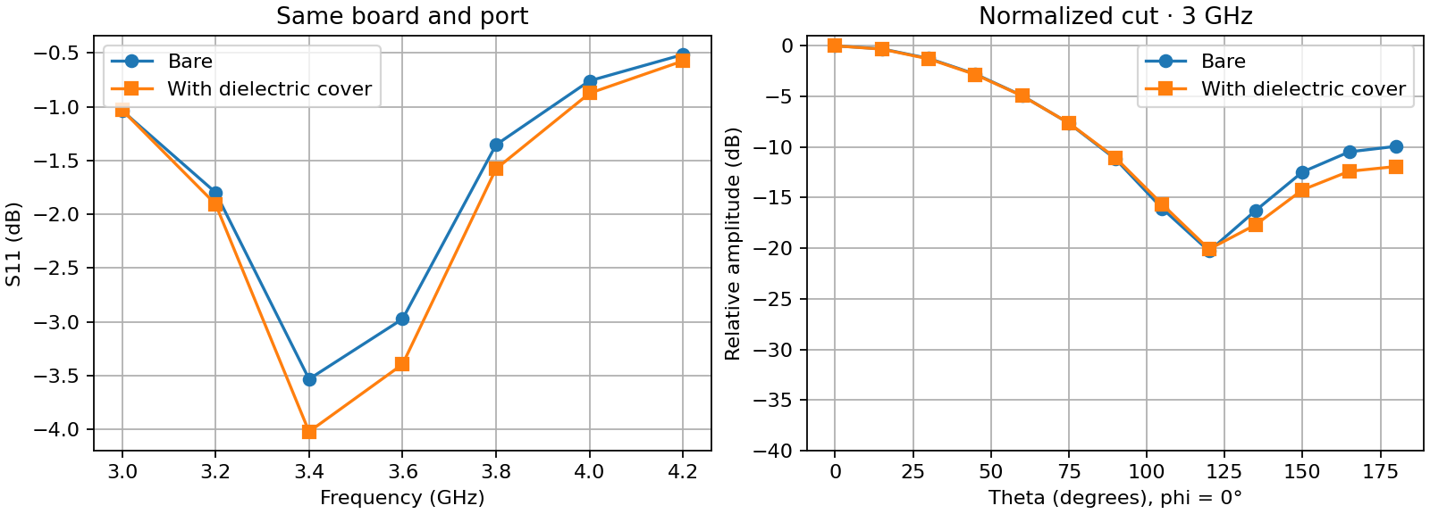
Both seven-frequency runs completed through SPIKE's isolated extension host with model_status: unvalidated; their saved results are bare_result.json and covered_result.json. The comparison_evidence.json checks identical board, port, frequency and requested mesh inputs. At 3.4 GHz, S11 was -3.53 dB bare and -4.02 dB covered. At 3 GHz, the independently peak-normalized relative field sample at theta 180°, phi 0° changed from -9.94 to -11.93 dB. This angular difference is a change in normalized pattern shape, not radome insertion loss or absolute gain.

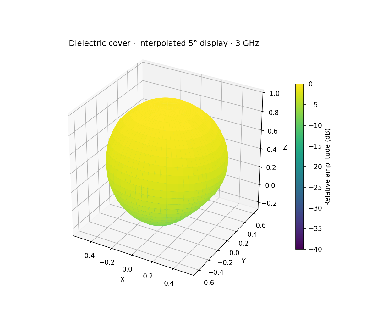
The paired S11 and angular-cut figure and interpolated 3D covered pattern are saved display artifacts. The 3D surface bilinearly interpolates relative linear amplitude from the solver's 13 × 25 angular grid to 5° spacing. SPIKE offers the same display interpolation, the original solved grid, and a relative pattern overlay in the EMI chamber. Its bench can be shown, made translucent, or hidden without changing the FEM case. None of those display choices creates new solved field values.

Bare and covered sweep and cut

Covered antenna interpolated relative pattern

Parts

141
QtyValueFootprintReferences
191k_0603PCM_fab:R_0603R1, R2, R3, R16, R17, R22, R23, R24, R25, R26, R27, R28, R29, R30, R31, R32 +3
16100n_50VPCM_fab:C_0603C2, C4, C6, C9, C13, C15, C17, C20, C22, C27, C29, C31, C32, C33, C35, C36
1110R_0603Resistor_SMD:R_0603_1608MetricR5, R6, R8, R9, R10, R11, R12, R13, R14, R15, R33
10SMD310HL-TPDiode_SMD:Nexperia_CFP3_SOD-123WD4, D5, D6, D7, D8, D9, D10, D11, D15, D16
9STP60NF06LPackage_TO_SOT_THT:TO-220-3_Horizontal_TabUpQ1, Q2, Q3, Q4, Q5, Q6, Q7, Q8, Q9
710u_50VCapacitor_SMD:C_0805_2012MetricC1, C3, C5, C19, C21, C28, C34
7TestPointTestPoint:TestPoint_Pad_D1.5mmTP1, TP2, TP3, TP4, TP5, TP6, TP7
601x04Connector_JST:JST_XH_B4B-XH-AM_1x04_P2.50mm_VerticalJ5, J7, J9, J10, J11, J15
6100u_100VCapacitor_THT:CP_Radial_D12.5mm_P5.00mmC7, C10, C11, C18, C23, C26
6stb01x02TerminalBlock:TerminalBlock_MaiXu_MX126-5.0-02P_1x02_P5.00mmJ2, J6, J8, J12, J13, J14
5SolderJumper_2_OpenJumper:SolderJumper-2_P1.3mm_Open_RoundedPad1.0x1.5mmJP6, JP7, JP8, JP9, JP10
4MountingHole_PadMountingHole:MountingHole_3.5mm_Pad_TopOnlyH1, H2, H3, H4
4SW_MEC_5EButton_Switch_SMD:SW_Push_1P1T_XKB_TS-1187ASW1, SW2, SW3, SW4
20.033R_2512Resistor_SMD:R_2512_6332Metric_Pad1.40x3.35mm_HandSolderR4, R7
21u_50VPCM_fab:C_0603C14, C16
2R_Potentiometer_TrimPotentiometer_THT:Potentiometer_Alps_RK09Y11_Single_HorizontalRV1, RV2
2redPCM_fab:LED_0603D2, D12
2yellowPCM_fab:LED_0603D13, D14
11.02k_0603PCM_fab:R_0603R38
110k_0603PCM_fab:R_0603R37
115A_100VPackage_TO_SOT_SMD:TO-252-2D3
11n_50VPCM_fab:C_0603C25
1AS5600L-ASOMPackage_SO:JEITA_SOIC-8_3.9x4.9mm_P1.27mmU5
1DRV8711Package_SO:HTSSOP-38-1EP_4.4x9.7mm_P0.5mm_EP2.74x4.75mm_ThermalViasU3
1Fuse_holder_10A696108003002:696108003002F1
1MCP1501-25xCHPackage_TO_SOT_SMD:SOT-23-6U6
1RBT10W24S12XPPower_RTB10:rtb10_fpU9
1RBT10W24S3V3XPPower_RTB10:rtb10_fpU10
1SC0918SC0918:MODULE_SC0918U2
1SolderJumper_2_BridgedJumper:SolderJumper-2_P1.3mm_Bridged_RoundedPad1.0x1.5mmJP5
1TC4420VOA713Package_SO:SOIC-8_3.9x4.9mm_P1.27mmU7
1TLV1701AIDBVRPackage_TO_SOT_SMD:SOT-23-5_HandSolderingU8

The 134 most common of 141 parts.

More from wayri/SPIKE

1
  • 4 layers29.5 × 64.5 mmIot esp eth ind, the printed circuit board in 3D

    Iot esp eth ind

    wayri/SPIKE

    PCB-focused multiphysics simulation, from board to complete assembly: PI, SI, circuits, thermal, EM/RF and mechanical workflows, with MCAD collaboration and a roadmap toward large-scale coupled assemblies.

    150 parts17

Similar boards

  • 2 layers83.8 × 53.3 mmSTS1 BATT TEST, the printed circuit board in 3D

    STS1 BATT TEST

    SpaceTeam/STS1_BATT_TEST

    10 parts1
  • 4 layers40 × 52.5 mmVAL3100, the printed circuit board in 3D

    VAL3100

    Valar-Systems/VAL3100

    The VAL3100 is now part of the Valar Motion mono-repo, alongside the VAL3000 and VAL3101 controllers:

    67 parts2CERN-OHL-S-2.0
  • 6 layers70.8 × 40.1 mmBLDC Driver, the printed circuit board in 3D

    BLDC Driver

    Aykut-Gencer-KARACA/BLDC-Driver

    PCB'nin Blender'da hazırlanmış 3D render'ı · tam çözünürlüklü video için görsele tıklayın

    120 parts
  • 2 layers100.5 × 52 mmGuitar Pedal, the printed circuit board in 3D

    Guitar Pedal

    he1ias/programmable-guitar-pedal

    A programmable acoustic guitar pedal that doubles as a wireless instrument recording device.

    19 parts
  • 2 layersSmartEggTimer, the printed circuit board in 3D

    SmartEggTimer

    meierh/Embedded_System_Hands_On_I

    All files related to the group project can be found in the Project folder. It contains the following parts of our project:

    66 parts
  • 2 layers83.2 × 161.9 mmActiveLoadMosfets, the printed circuit board in 3D

    ActiveLoadMosfets

    jakubprzybytek/ActiveLoad

    Active Load for testing power supply circuits

    76 parts
  • 6 layers100 × 114 mmMTE USB HUB, the printed circuit board in 3D

    MTE USB HUB

    MicroType-Engineering/MTE_USB_HUB

    As designed on the MicroType Engineering's YouTube series: https://youtu.be/uzqXgHHZUUs

    159 parts41GPL-2.0

Questions

How big is the Ebrake1 PCB?

It measures 144 × 83.5 mm and has 4 copper layers, 1.6 mm thick.

What parts does the Ebrake1 use?

141 parts, built around the AS5600L-ASOM, DRV8711DCPR, TC4420VOA713 and RBT10W24S12. The full list of its parts is on this page, with links to each part's symbol and footprint where PCBKit's library has them.

Where can I download the Ebrake1 KiCad files?

From the wayri/SPIKE repository on GitHub, at the commit this page was made from: the board is app/public/demo/ebrake1.kicad_pcb and its schematic examples/esp32/source/iot-esp-eth-ind-cpu.kicad_sch. PCBKit opens the board in the browser, with nothing to install.

Can I use the Ebrake1 design in my own project?

Its repository states no licence, so its author keeps all rights: ask wayri before reusing the design.