2 layers28.3 × 39.8 mm
LevelShifter
gusmanb/logicanalyzer
24 channel, 100Msps logic analyzer hardware and software
21 parts5.1kGPL-3.0

 VX7FAR/Servo-Tester
A servo tester is basically a device someone can use to check whether their servo motors work or not and this can be very essential as it can help you to check your servo motors before having to write new code just to…
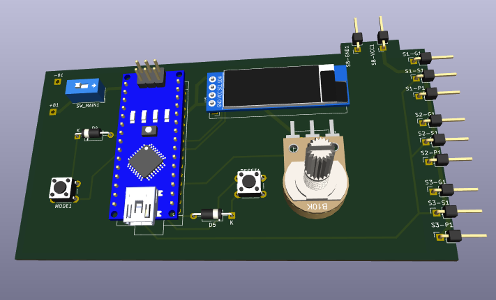
Servo Tester is an open-source printed circuit board by VX7FAR, from the VX7FAR/Servo-Tester repository on GitHub. It is a 2-layer board of 113 × 62.5 mm with 21 parts on 33 nets, routed with 68 tracks and 0 vias.
Its parts include 11 switches, 2 diodes and 1 IC. It belongs with the robots and motor control boards and the AVR (ATmega, ATtiny) boards of this library.
A servo tester is basically a device someone can use to check whether their servo motors work or not and this can be very essential as it can help you to check your servo motors before having to write new code just to run a single servo. Most of the servo need 1ms to 2ms pulse so that it moves from 0 to 180 degrees respectively.
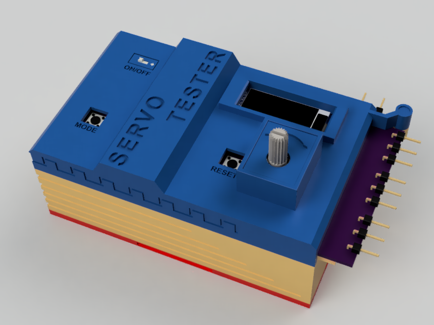
Here is a normal view of servo tester:
Exploded View:
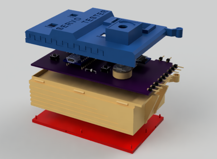
The main component here is Arduino Nano I chose this specially because this servo tester also has a 0.91 inch display module. The display shows stats like speed, angle, mode, etc. It also feature a potentiometer to control different things based on the mode selected It also has two buttons one is for resetting to original position and other is for switching between sweep and manual mode.
| Component | Quantity |
|---|---|
| Arduino Nano | 1 |
| Arduino Data Cable | 1 |
| 0.91" OLED Display Module | 1 |
| Push Button | 2 |
| Toggle Switch | 1 |
| PCB | 1 |
| Male connector pins | 11 |
| Top enclosure | 1 |
| Middle Enclosure | 1 |
| Bottom Panel | 1 |
| 6-12V DC Power Source | 1 |
| Servo Motor (SG90) | 1 |
| 4x1.5mm magnets | 2 |
| Diodes | 2 |
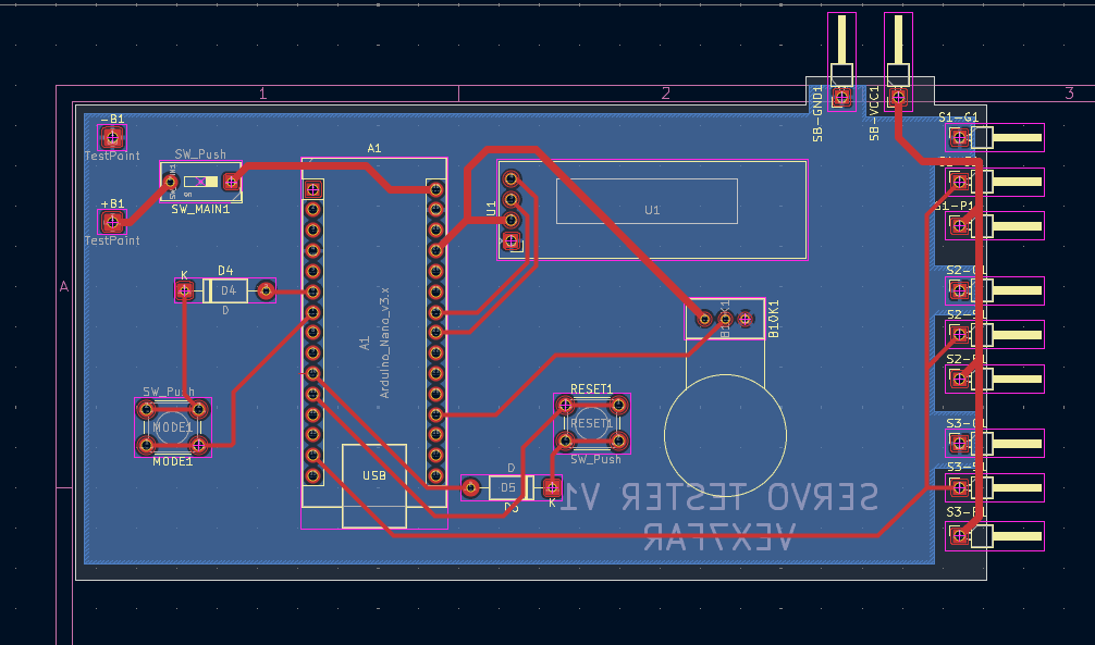
An overview of what the PCB is like.
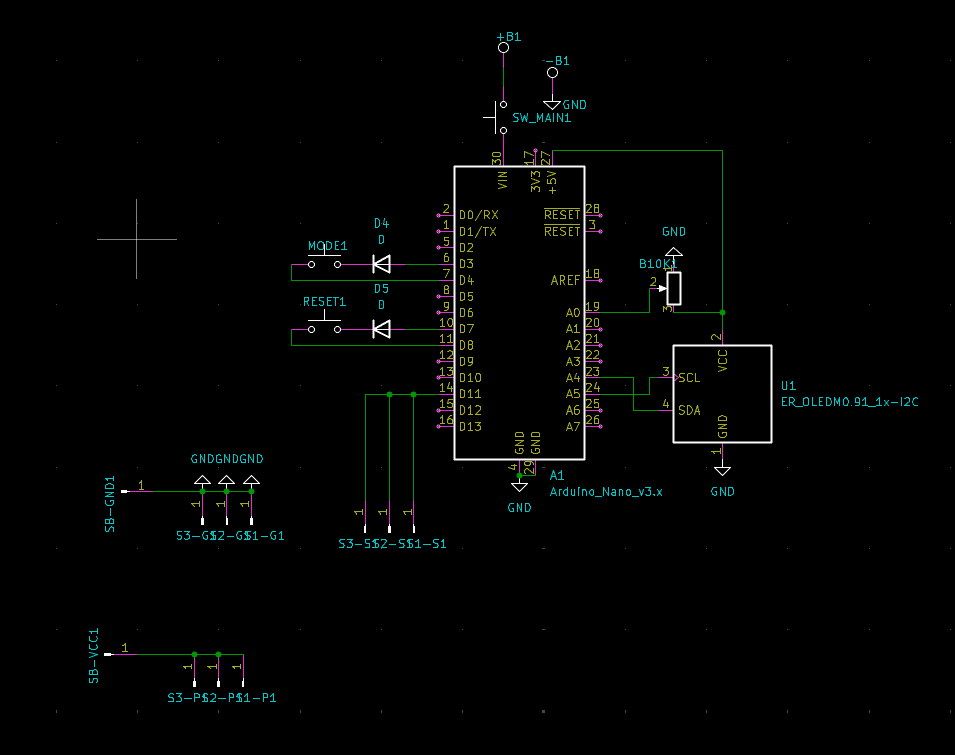
Circuit:
PCB:
PCB 3D Model:
from src/main.cpp and header is in include/animation.h.Adafruit_SSD1306.h and Adafruit_GFX.h.PCB folder contains everything related to PCB like gerber file (PCB-gerber.zip), kicad files and also the 3D model of PCB (servo tester.step).assets folder contains things that are not really important for making the project but I kept them for having a bit easy while working and writing the README. You can freely ignore that folder if you want to.| Qty | Value | Footprint | References |
|---|---|---|---|
| 11 | Conn_01x01_Pin | Connector_PinHeader_2.54mm:PinHeader_1x01_P2.54mm_Horizontal | S1-G1, S1-P1, S1-S1, S2-G1, S2-P1, S2-S1, S3-G1, S3-P1, S3-S1, SB-GND1, SB-VCC1 |
| 2 | D | Diode_THT:D_A-405_P10.16mm_Horizontal | D4, D5 |
| 2 | SW_Push | Button_Switch_THT:SW_PUSH_6mm | MODE1, RESET1 |
| 2 | TestPoint | Connector_Wire:SolderWire-0.5sqmm_1x01_D0.9mm_OD2.1mm | -B1, +B1 |
| 1 | Arduino_Nano_v3.x | Module:Arduino_Nano | A1 |
| 1 | ER_OLEDM0.91_1x-I2C | Display:ER_OLEDM0.91_1x-I2C | U1 |
| 1 | R_Potentiometer | Potentiometer_THT:Potentiometer_Bourns_3386C_Horizontal | B10K1 |
| 1 | SW_Push | Button_Switch_THT:SW_DIP_SPSTx01_Slide_9.78x4.72mm_W7.62mm_P2.54mm | SW_MAIN1 |
It measures 113 × 62.5 mm and has 2 copper layers, 1.6 mm thick.
21 parts. The full list of its parts is on this page, with links to each part's symbol and footprint where PCBKit's library has them.
From the VX7FAR/Servo-Tester repository on GitHub, at the commit this page was made from: the board is PCB/servo tester.kicad_pcb and its schematic PCB/servo tester.kicad_sch. PCBKit opens the board in the browser, with nothing to install.
Its repository states no licence, so its author keeps all rights: ask VX7FAR before reusing the design.
gusmanb/logicanalyzer
24 channel, 100Msps logic analyzer hardware and software

mntmn/amiga2000-gfxcard
MNT VA2000, an Open Source Amiga 2/3/4000 Graphics Card (Zorro II/III), written in Verilog


hackclub/OnBoard
💡 Join 1,000 teenagers and make your first PCB with a $100 grant!

drandyhaas/KiCadRoutingTools
A set of Python/Rust tools to aid routing in KiCad

Arrow-air/project-quiver
Project Quiver documentation, designs, and project artifacts.

