Skip to the content
PCBKitNew board
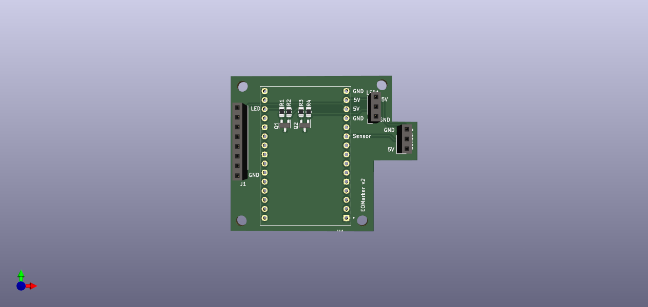
2 layers52.2 × 43.6 mmPCB ESP32-C3-DevKitC-02, the printed circuit board in 3D

PCB ESP32-C3-DevKitC-02

vives-project-xp/EOMarkers3

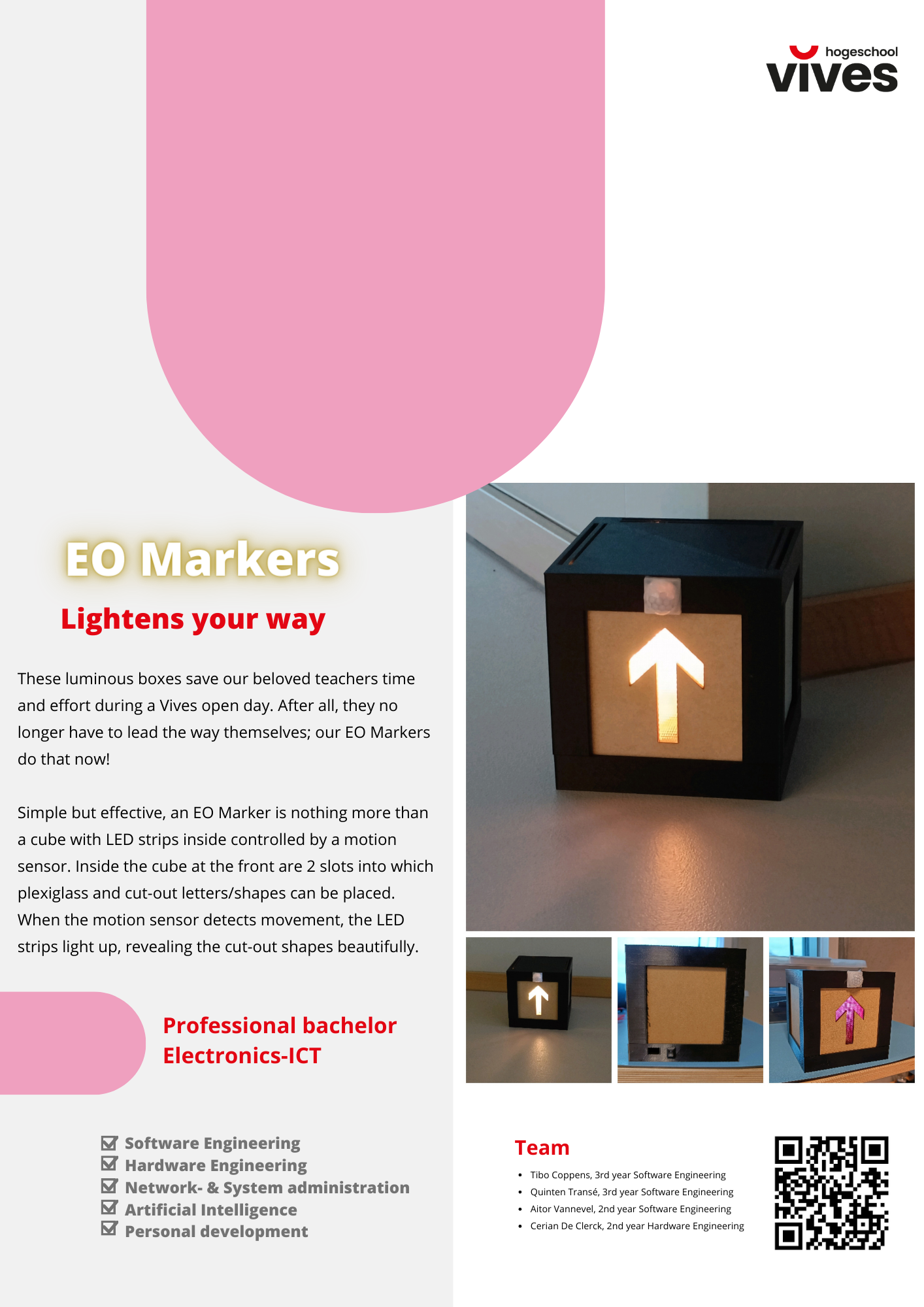
Develop small standalone boxes that light up when someone approaches them. The boxes can be fitted with a plexi with Electronics-ICT and a direction indication via an arrow.

Size
52.2 × 43.6 mm
Copper layers
2
Thickness
1.6 mm
Parts
10
Nets
29
Pads
58
Tracks, vias
50, 0
Pours
2
Routed
Yes
KiCad
KiCad 7 (file 20221018)
Created
13 Sep 2023
Updated
18 Dec 2023

Overview

PCB ESP32-C3-DevKitC-02 is an open-source printed circuit board by vives-project-xp, from the vives-project-xp/EOMarkers repository on GitHub. It is a 2-layer board of 52.2 × 43.6 mm with 10 parts on 29 nets, routed with 50 tracks and 0 vias.

It is built around the ESP32-C3-DEVKITC-02. Its parts include 4 resistors, 2 diodes, 2 transistors, 1 IC and 1 connector. It belongs with the ESP32 and RISC-V boards of this library.

Main components

1

README

readme.md

EO-Markers

Develop small standalone boxes that light up when someone approaches them. The boxes can be fitted with a plexi with Electronics-ICT and a direction indication via an arrow.

Layout Github Repo

bash
.
├── 3d tekening
│   ├── 3D_Bottom.png
│   ├── 3D_Main.png
│   └── README.md
├── Affiche
│   └── EO Markers Affiche.png
├── AndroidStudio
│   ├── EO-Markers
│   │   └── app
│   └── README.md
├── Arduino
│   ├── EO-Markers
│   │   ├── EO-Markers.cpp
│   │   └── EXAMPLE-config.h
│   └── README.md
├── img
│   ├── qr.png
│   └── project_canvas.png
│   └── potentiometers.jpg
│   └── schakelaar.jpg
├── PCB
│   ├── PCB
|   ├── PCB_ESP32-C3-DevKitM-1

Table of contents

Planning

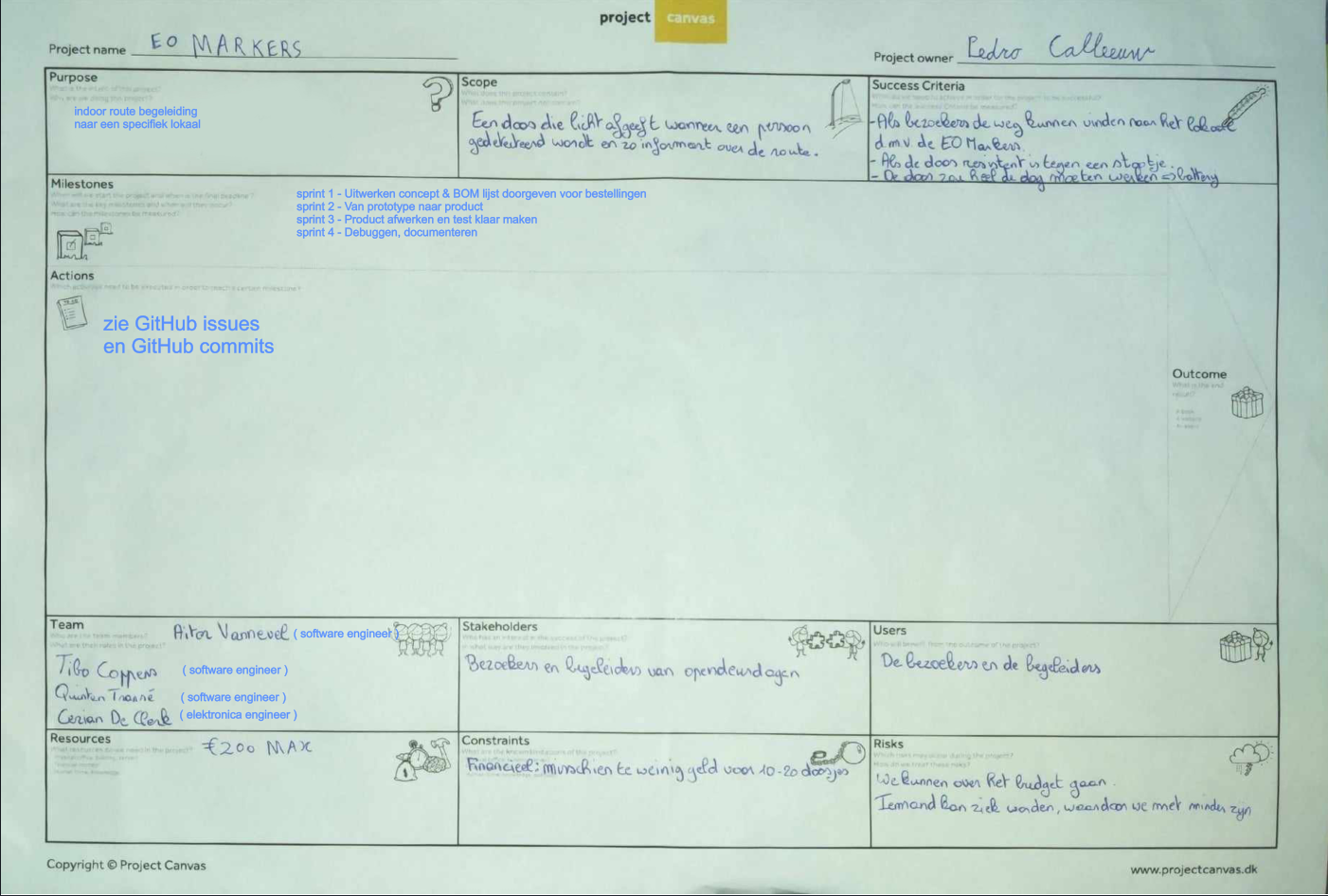
  • sprint 1 - Uitwerken concept & BOM lijst doorgeven voor bestellingen
  • sprint 2 - Van prototype naar product
  • sprint 3 - Product afwerken en test klaar maken
  • sprint 4 - Debuggen, documenteren

Canvas

Canvas

Affiche

Affiche

How to use

  1. It is important that the batteries are fully charged, as they are rechargeable. A USB-C port is provided as an alternative power supply.
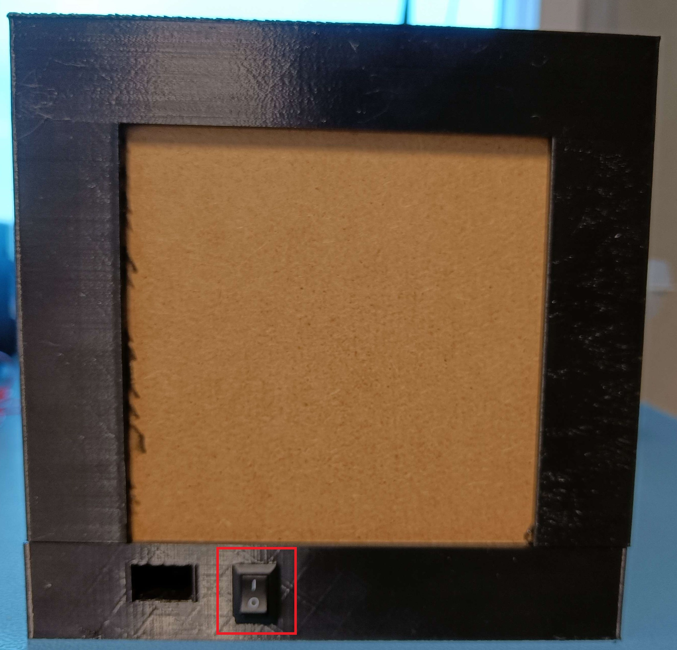
  2. Turn the switch on.

schakelaar

  1. Wait about 10 seconds. The LED strips will then light up whenever the sensor, attached to the front of the marker, detects movement.
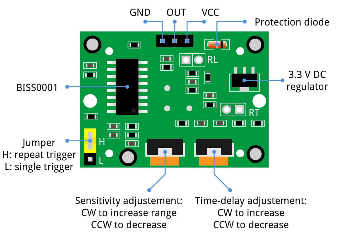
  2. You can change the distance at which the sensor detects movement and the duration of lighting by turning the potentiometers as shown in the image.

potentiometers

  1. Each time the light goes out, there is a period of 2.5 seconds before the sensor can detect movement again.
  2. After using the EO marker, switch it off and charge the batteries.

3D drawing

more info: 3D Tekening

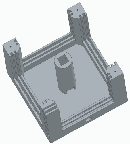
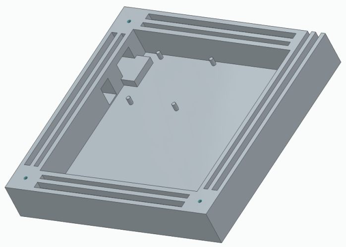
This is the base of the cube. The sensor is placed in the small round hole, the LED strips stick to the inside of the posts and the cables are inserted through the middle part. A reflective film has been applied to this area, which helps to spread the light around. A diffuser (plexiglass) is slid into the furthest slot and a plywood wall, with or without directions, is placed in the nearest slot.

TopTop

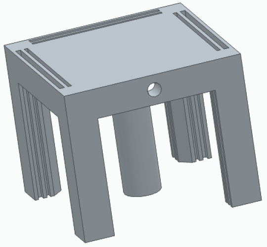
This is the bottom of the cube. This is where the PCB, battery holder and cables end up. A hole is provided for a USB cable as secondary power. These 2 prints are screwed together with an M3 screw or bolt.

Bottom

Android Studio

more info: Android Studio

Arduino

more info: Arduino

PCB

more info: PCB

PCB print

The PCB consists of a pair of connectors for the ESP, LED strip, sensor and USB-C port. These are female headers, so they fit in perfectly. The connectors are internally connected on the PCB.

PCB

PCB schematic

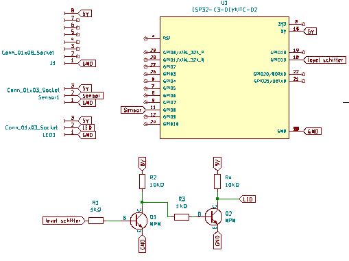
The circuit consists of 1 ESP, powered by a USB cable or a 5V battery pack connected in parallel on the j1 connector with a diode from battery pack to connector (4 rechargeable AA batteries). 3 female headers for the LED strips, 3 female headers for the sensor, 8 female headers for the USB-C port and a diode to stop current to the batteries.

Measurements: U LED-strips (off): 4,1V; U LED-strips (on): 3,1V

U Batteries (leds off): 4.9V; U Batteries (leds on): 4.3V

U Diode (leds off): 0.72V; U Diode (leds on): 0.86V

U Sensor (leds off): 2.98V; U Sensor (leds on): 2.55V

U ESP (leds off): 4.1V; U ESP (leds on): 3.45V

Schakeling

Parts

10
QtyValueFootprintReferences
210KΩResistor_SMD:R_0805_2012MetricR2, R4
21KΩResistor_SMD:R_0805_2012MetricR1, R3
2Conn_01x03_SocketConnector_PinSocket_2.54mm:PinSocket_1x03_P2.54mm_VerticalLED1, Sensor1
2NPNPackage_TO_SOT_SMD:SOT-23Q1, Q2
1Conn_01x08_SocketConnector_PinSocket_2.54mm:PinSocket_1x08_P2.54mm_VerticalJ1
1ESP32-C3-DEVKITC-02ESP32-C3-DEVKITC-02:XCVR_ESP32-C3-DEVKITC-02U1

Questions

How big is the PCB ESP32-C3-DevKitC-02 PCB?

It measures 52.2 × 43.6 mm and has 2 copper layers, 1.6 mm thick.

What parts does the PCB ESP32-C3-DevKitC-02 use?

10 parts, built around the ESP32-C3-DEVKITC-02. The full list of its parts is on this page, with links to each part's symbol and footprint where PCBKit's library has them.

Where can I download the PCB ESP32-C3-DevKitC-02 KiCad files?

From the vives-project-xp/EOMarkers repository on GitHub, at the commit this page was made from: the board is PCB/PCB_ESP32-C3-DevKitC-02/PCB.kicad_pcb and its schematic PCB/PCB/PCB.kicad_sch. PCBKit opens the board in the browser, with nothing to install.

Can I use the PCB ESP32-C3-DevKitC-02 design in my own project?

Its repository states no licence, so its author keeps all rights: ask vives-project-xp before reusing the design.

More from vives-project-xp/EOMarkers

2
  • 2 layers52.2 × 43.6 mmPCB ESP32-C3-DevKitM-1, the printed circuit board in 3D

    PCB ESP32-C3-DevKitM-1

    vives-project-xp/EOMarkers

    Develop small standalone boxes that light up when someone approaches them. The boxes can be fitted with a plexi with Electronics-ICT and a direction indication via an arrow.
    10 parts3
  • 2 layers50.7 × 43.5 mmEOMarkers, the printed circuit board in 3D

    EOMarkers

    vives-project-xp/EOMarkers

    Develop small standalone boxes that light up when someone approaches them. The boxes can be fitted with a plexi with Electronics-ICT and a direction indication via an arrow.
    4 parts3

Similar boards

  • 2 layers121.5 × 60.5 mmRemote, the printed circuit board in 3D

    Remote

    ElektroJonas/DIY-Quadcopter

    This repository contains the control algorithm for a quadcopter drone on an ESP32 as well as electrical schematics and a pcb design.

    24 parts82
  • 2 layers98.9 × 44.1 mmShuttle Tracker Node, the printed circuit board in 3D

    Shuttle Tracker Node

    wtg/Shuttle-Tracker-Node

    Resources, schematics, and other information for Shuttle Tracker Node

    27 parts3
  • 2 layers27.9 × 62.4 mmF1 car, the printed circuit board in 3D

    F1 car

    tommasoclini/esp32_f1

    esp32 f1 car

    2 parts2MIT
  • 2 layers49.2 × 40.2 mmPcb 1 new, the printed circuit board in 3D

    Pcb 1 new

    Haridharan-D/eSim_PCB_Design_Project_Files

    Battery-powered ESP32 air quality monitor with a soft power latch, MCP16251 boost converter, and ADS1115 ADC — implemented and simulated in eSim.

    20 partsGPL-3.0
  • 2 layers49.3 × 66.5 mmHeishamon lr pdc, the printed circuit board in 3D

    Heishamon lr pdc

    lrodorigo/heishamon-lr-aquarea-board

    A simple alternative hardware implementation for the great HeishaMon board for communicating with Panasonic heatpumps

    30 parts
  • 2 layers63.3 × 45.5 mmSd bt streamer, the printed circuit board in 3D

    Sd bt streamer

    pluggee/G3X_SD_BT

    SD card streamer

    7 partsGPL-3.0
  • 2 layers121.5 × 60.5 mmRemote, the printed circuit board in 3D

    Remote

    Siggeaxe/DIY_Quadcopter

    Cool Quadcopter UAV built from scratch!

    26 parts
  • 2 layers100 × 80 mmKnock knock esp32, the printed circuit board in 3D

    Knock knock esp32

    Universumgames/knock-knock-esp32

    A knock pattern recognition with esp32

    26 partsCC-BY-4.0