6 layers90.2 × 95.9 mm

 visionspacetec/VST104-Sierra10
VST104 single OBC board - referred as board_sierra
Board sierra is an open-source printed circuit board by visionspacetec, from the visionspacetec/VST104-Sierra repository on GitHub. It is a 6-layer board of 90.2 × 95.9 mm with 245 parts on 439 nets, routed with 4,702 tracks and 549 vias.
It is built around the MCP9804-E/MC, CY15B102Q-SXA and SP3012-06UTG. Its parts include 79 resistors, 73 capacitors, 3 ICs, 3 diodes and 3 transistors. It belongs with the STM32 boards of this library.


This repository contains the KiCad project and other documents created during the development of Board Sierra under VST104 project. This PC104 CubeSats module is a single redundant onboard computer designed to fulfill most space industry requirements.
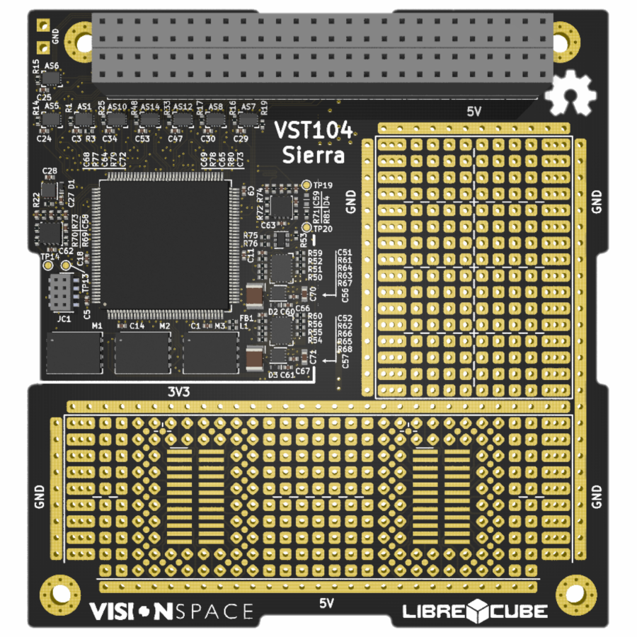
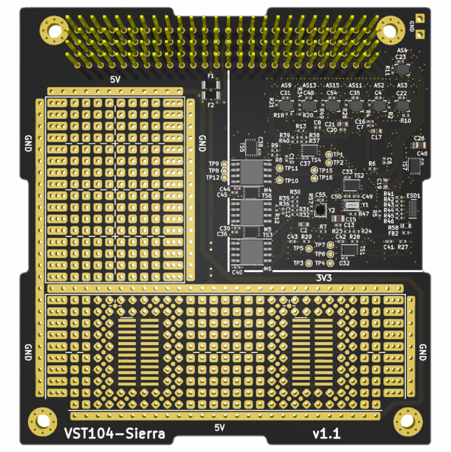
Fig 1. Board Sierra OBC module 3D visualisation top (left) and bottom (right) side.
processor: This onboard computer is driven by state of the art, ultra-low-power STM32L496 ARM® Cortex®-M4 core microcontroller. This MCU is capable of running up to 78[MHz] in our design.clock: Microcontroller is driven by two external clock sources. Low-speed external 32.768[kHz] oscillator (LSE) and high-speed external 26[MHz] oscillator (HSE). The MCU is capable of temporarily disable the HSE to achieve better power consumption.memory: Two groups of triple redundant external memories are available for data storage and processing. The triple redundancy was chosen as an effective measure against single event effects. The first memory group is 256 [Mbit] Flash wired via Quad-SPI interface and the second one is 2 [Mbit] F-RAM using SPI.peripherals: This module can communicate with other CubeSat subsystems using a wide variety of redundant protocols. The main PC104 header is capable of connecting to 2x CAN-BUS, 3x I2C, 4x UART (with CTS and RTS), 2xSPI (2 enables each), and 22 general purpose A/D I/O pins. All of the listed peripherals are wired thru separated isolators controlled by the MCU. On top of that, separate traces are used for system check and maintenance signals, such as: WatchDog, KillSwitch, CPUmode, Sync, FaultCollector. The pinout of these interferences is shown in figure 3.connectivity: A user can program and debug this OBC using SWI and/or UART interface. These interfaces are accessible on the board's edge on a separate connector with integrated electrostatic discharge protection circuitry. The SWI interface is compatible with STM ST-LINK series programmers (including SWO pin).
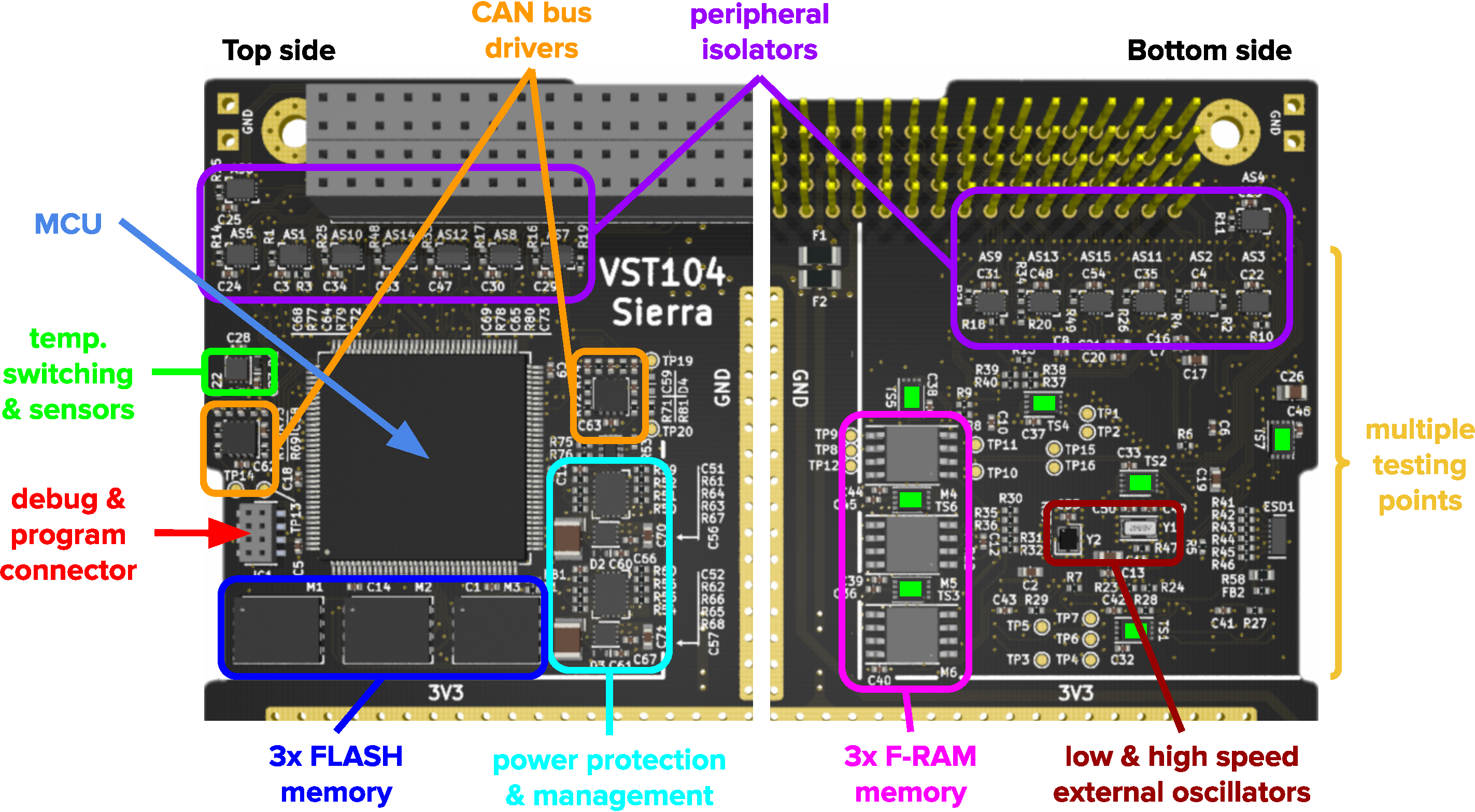
Fig 2. Important circuitry groups on top (left) and bottom (right) side of the module.
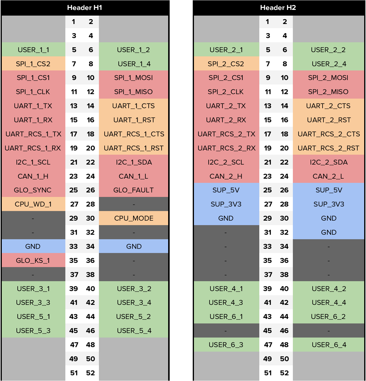
Fig 3. PC104 header pinout supported by this OBC module.
A separate 2x4 female format connector on the board's left side is used for debugging and programming. SWI and UART5 interfaces of the boarded STM32 microprocessor are wired to this connector, as shown in figure 4. This interface is fully compatible with STM ST-Link family programmers.
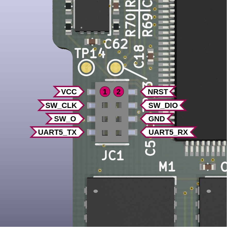
Fig 4. Pinout of the debug and program connector.
The design of this PC 104 SBC module was processed under evaluation of the following documents:
[1] : STM32L496xx datasheet
[2] : STM32L496xx getting started manual
[3] : STM32 oscillator design guide
[4] : STM32 Quad-SPI interface
[5] : Common mode chokes in CAN networks
[6] : Isolated CAN systems with protection
| Qty | Value | Footprint | References |
|---|---|---|---|
| 35 | 100n | VST104_footprints:C_SMD_0402 | C1, C10, C11, C12, C13, C14, C16, C18, C20, C27, C32, C33, C36, C37, C38, C39 +19 |
| 23 | 100k | VST104_footprints:R_SMD_0402 | R1, R2, R3, R10, R11, R14, R15, R16, R17, R18, R19, R20, R21, R22, R25, R26 +7 |
| 18 | test_point | VST104_footprints:scope_PAD_1mm | TP1, TP2, TP3, TP4, TP5, TP6, TP7, TP10, TP11, TP12, TP13, TP14, TP15, TP16, TP19, TP20 +2 |
| 16 | 22 | VST104_footprints:R_SMD_0402 | R6, R7, R8, R9, R12, R13, R41, R42, R43, R44, R45, R46, R69, R70, R71, R72 |
| 15 | 10k | VST104_footprints:R_SMD_0402 | R5, R23, R24, R27, R28, R29, R30, R31, R32, R53, R67, R68, R73, R74, R76 |
| 15 | 10n | VST104_footprints:C_SMD_0402 | C3, C4, C22, C23, C24, C25, C29, C30, C31, C34, C35, C47, C48, C53, C54 |
| 15 | DGQ2788A | VST104_footprints:mini_QFN-16-1.8x2.6mm | AS1, AS2, AS3, AS4, AS5, AS6, AS7, AS8, AS9, AS10, AS11, AS12, AS13, AS14, AS15 |
| 7 | MCP9804 | VST104_footprints:DFN-8_3.0x2.0mm_EP | TS1, TS2, TS3, TS4, TS5, TS6, TS7 |
| 6 | trace_0.2mm | VST104_footprints:trace_arc_0.2mm | TRC4, TRC5, TRC6, TRC7, TRC8, TRC9 |
| 4 | 100p | VST104_footprints:C_SMD_0402 | C68, C69, C72, C73 |
| 4 | 1u | VST104_footprints:C_SMD_0603 | C2, C17, C70, C71 |
| 4 | 4k7 | VST104_footprints:R_SMD_0402 | R37, R38, R39, R40 |
| 4 | 60.4 | VST104_footprints:R_SMD_0402 | R77, R78, R79, R80 |
| 4 | MountingHole_Pad | VST104_footprints:MountingHole_3.2mm_M3_Pad_Via | MH1, MH2, MH3, MH4 |
| 4 | PC104_SO-24_universal | VST104_footprints:PC104_SO-24_universal | UA1, UA2, UA3, UA4 |
| 3 | 1n | VST104_footprints:C_SMD_0402 | C28, C66, C67 |
| 3 | 280k | VST104_footprints:R_SMD_0402 | R47, R50, R54 |
| 3 | CY15B102Q | VST104_footprints:SOIC-8_208_5.23x5.23mm | M4, M5, M6 |
| 3 | S25FL256L | VST104_footprints:WSON-8_6.0x8.0mm_EP | M1, M2, M3 |
| 3 | Schottky diode | VST104_footprints:D_SMD_0402 | D1, D2, D3 |
| 3 | trace_0.173mm | VST104_footprints:trace_arc_0.173mm | TRC1, TRC2, TRC3 |
| 2 | 0 | VST104_footprints:R_SMD_1206 | F1, F2 |
| 2 | 100u | VST104_footprints:C_SMD_1210 | C56, C57 |
| 2 | 10u | VST104_footprints:C_SMD_0805 | C15, C26 |
| 2 | 110k | VST104_footprints:R_SMD_0402 | R63, R65 |
| 2 | 120@100M | VST104_footprints:R_SMD_0402 | FB1, FB2 |
| 2 | 17p | VST104_footprints:C_SMD_0402 | C49, C50 |
| 2 | 33k2 | VST104_footprints:R_SMD_0402 | R61, R62 |
| 2 | 4n7 | VST104_footprints:C_SMD_0402 | C64, C65 |
| 2 | 4u7 | VST104_footprints:C_SMD_0603 | C19, C21 |
| 2 | 75k | VST104_footprints:R_SMD_0402 | R59, R60 |
| 2 | Conn_02x26_Odd_Even | VST104_footprints:ESQ-126-39-x-D | H1, H2 |
| 2 | GND | VST104_footprints:scope_GND | TP17, TP18 |
| 2 | TCAN1051-Q1 | VST104_footprints:VSON-8_3.0x3.0mm_EPV | U2, U3 |
| 2 | TPS22965W-Q1 | VST104_footprints:WSON-8_2.0x2.0mm_EPV | Q2, Q3 |
| 2 | TPS25940-Q1 | VST104_footprints:WQFN-20_4.0x3.0mm_EPV | EF1, EF2 |
| 1 | 100 0.25W | VST104_footprints:R_SMD_0603 | R58 |
| 1 | 10u | VST104_footprints:L_SMD_0603 | L1 |
| 1 | 115k | VST104_footprints:R_SMD_0402 | R52 |
| 1 | 15n | VST104_footprints:C_SMD_0402 | C52 |
| 1 | 1k | VST104_footprints:R_SMD_0402 | R57 |
| 1 | 22k6 | VST104_footprints:R_SMD_0402 | R51 |
| 1 | 22n | VST104_footprints:C_SMD_0402 | C51 |
| 1 | 31k6 | VST104_footprints:R_SMD_0402 | R66 |
| 1 | 60k4 | VST104_footprints:R_SMD_0402 | R64 |
| 1 | 63k4 | VST104_footprints:R_SMD_0402 | R56 |
| 1 | 74LVC1G11-Q100 | VST104_footprints:SOT-363_TSSOP-6_2.0x1.25mm | LG1 |
| 1 | 8k66 | VST104_footprints:R_SMD_0402 | R55 |
| 1 | ABS07AIG | VST104_footprints:LSE_3.2x1.5mm | Y1 |
| 1 | Conn_01x03 | VST104_footprints:PC104_universal_OBC&FPGA | UA5 |
| 1 | ResinHole | VST104_footprints:MountingHole_1.2mm | RH1 |
| 1 | SP3012-06 | VST104_footprints:uDFN-14_3.5x1.35mm | ESD1 |
| 1 | STM32L496ZGTx | VST104_footprints:LQFP-144_20x20mm_P0.5mm | U1 |
| 1 | SW&UART | VST104_footprints:CLP-104-02-x-D | JC1 |
| 1 | SiT8924 | VST104_footprints:HSE_2.0x1.6mm | Y2 |
| 1 | TPS22965-Q1 | VST104_footprints:WSON-8_2.0x2.0mm_EPV | Q1 |
| 1 | logo | VST104_logos:VST_logo_horizontal_700 | LOGO1 |
| 1 | logo | VST104_logos:LibreCube_logo_22.4mm | LOGO2 |
| 1 | logo | VST104_logos:OSH_logo_8mm | LOGO3 |

Junkz3/wrench-board
A senior microsoldering technician, available to every repair shop from the seasoned pro to the apprentice. Powered by Claude Opus 5


mvalancy/IC_Breakouts
See Getting started for the project files and legacy KiCad notes.

schmidtmt/openmotorbridge
The comprehensive technical specification is split into 18 logically organized chapters:


It measures 90.2 × 95.9 mm and has 6 copper layers, 1.57 mm thick.
245 parts, built around the MCP9804-E/MC, CY15B102Q-SXA and SP3012-06UTG. The full list of its parts is on this page, with links to each part's symbol and footprint where PCBKit's library has them.
From the visionspacetec/VST104-Sierra repository on GitHub, at the commit this page was made from: the board is board_sierra.kicad_pcb. PCBKit opens the board in the browser, with nothing to install.
Its repository states no licence, so its author keeps all rights: ask visionspacetec before reusing the design.