2 layers100 × 70 mm
Valvenode
vinthewrench/valvenode
Wired RS-485 field-bus irrigation valve controller for Raspberry Pi farm automation
44 parts15

 vinthewrench/valvenode15
Wired RS-485 field-bus irrigation valve controller for Raspberry Pi farm automation
Valvenode master is an open-source printed circuit board by vinthewrench, from the vinthewrench/valvenode repository on GitHub. It is a 2-layer board of 90 × 60 mm with 54 parts on 64 nets, routed with 369 tracks and 3 vias.
It is built around the ATMEGA88PB-AU, MAX485EPA(LX) and ULN2003A, with the 151033GS03000, 151033RS03000 and 151034BS03000 among its other parts. Its parts include 13 resistors, 10 capacitors, 8 connectors, 5 diodes and 4 ICs. It belongs with the audio and music boards and the AVR (ATmega, ATtiny) boards of this library.


ValveNode is a wired field-bus irrigation valve-control system for my Raspberry Pi farm automation stack.
This project is a continuation of the work described in Off-Grid Farm Automation with Raspberry Pi.
The irrigation side started with a Raspberry Pi, relay outputs, and conventional sprinkler valve wiring, described in Raspberry Pi Internet of Things - part 2: Controlling the Irrigation valves. That proved the basic idea: local software can control real irrigation hardware without a cloud service or proprietary controller. It also exposed the usual field problems: long wire runs, voltage drop, power loss, serviceability, and too many individual valve wires returning to one box.
I later experimented with more efficient solenoid drive hardware using a DRV103 in Not Another Sprinkler Valve Article. That design gives a conventional valve a strong opening pulse and then reduces average power with PWM, which matters for long wire runs and battery-backed operation.
As the farm kept expanding, the wiring problem started to matter more than the valve-control problem. Every new irrigation zone meant another long wire run back to the controller, more trenching, more splices, more voltage drop, and more things to troubleshoot later. At that point, spending a few extra dollars per valve for latching solenoids was worth it if it let the field wiring become a simple 4-wire RS-485 network.
ValveNode takes the next step: instead of pulling every valve wire back to the controller, it moves small controller cards out into the field.
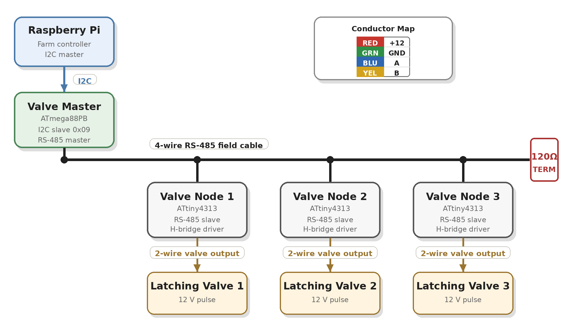
A Raspberry Pi talks to a Valve Master over I2C. The Valve Master starts a 4-wire RS-485 field cable carrying power and data. Valve Node cards sit along that cable, and each card drives a local latching irrigation solenoid with a short polarity-controlled pulse.
The goal is simple: irrigation control that is local, wired, understandable, repairable, and expandable.
The project has two primary components:
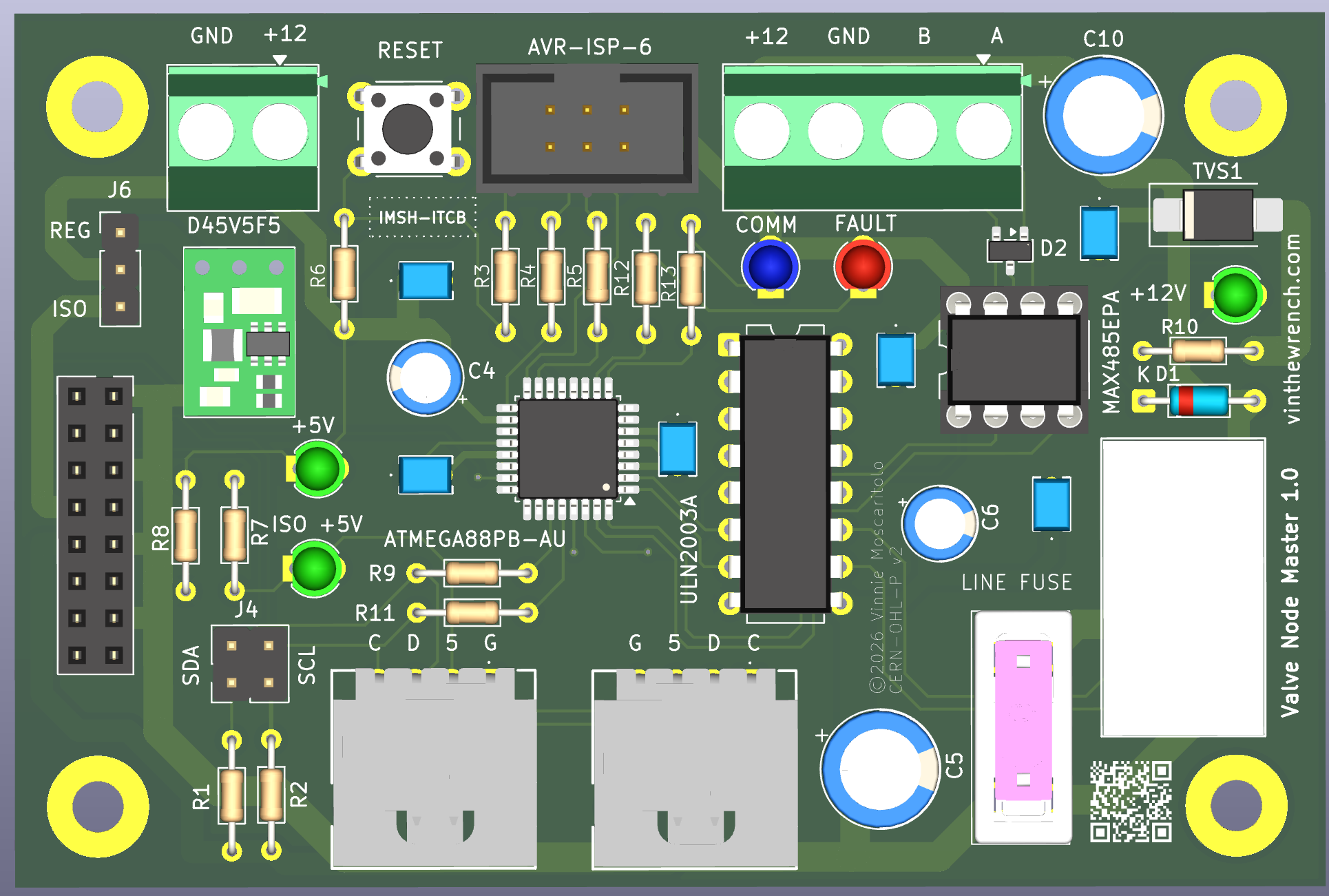
valvenode-master
ATmega88PB-based I2C-to-RS-485 master controller.
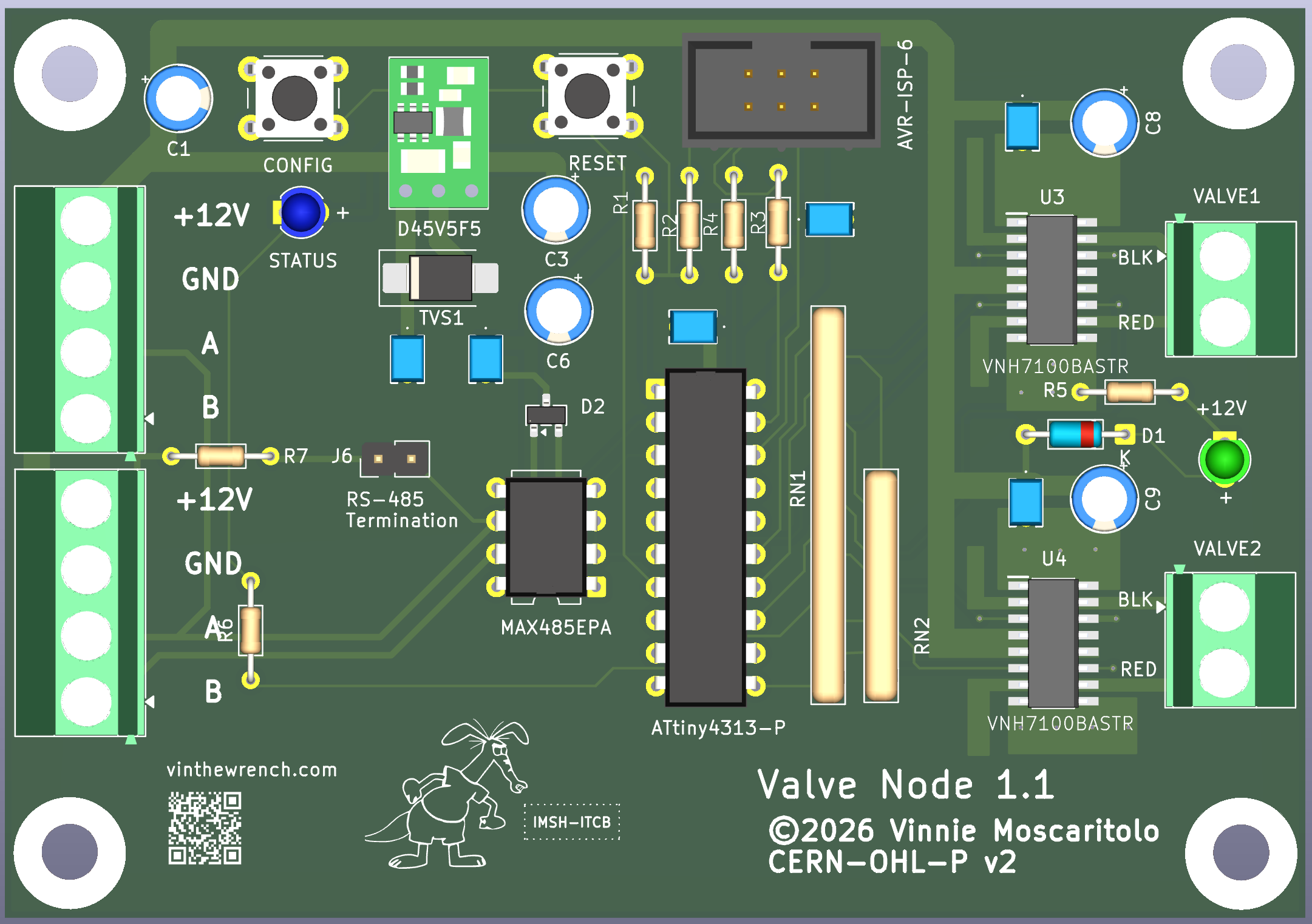
valvenode-slave
ATtiny4313-based RS-485 valve node for controlling latching irrigation valves.
The upstream controller talks to the Valve Master over I2C. The Valve Master controls field power and communicates with downstream Valve Nodes over RS-485.
ValveNode is designed around low-voltage DC latching irrigation solenoids. The initial supported solenoids are:
| Manufacturer | Part | Description | Notes |
|---|---|---|---|
| Hunter | 458200 | DC latching solenoid | Common Hunter solenoid for battery-operated and DC-latching valve control |
| Rain Bird | K80920 / TBOSPSOL | 9 V DC potted latching solenoid | Fits many Rain Bird valve bodies, including DV, DVF, ASVF, PGA, PEB, PESB, GB, EFB-CP, BPE, and BPES series valves |
A latching solenoid is not powered continuously. The Valve Node drives it with a short polarity-controlled pulse through the H-bridge: one polarity opens the valve, the opposite polarity closes it, and then the output is turned off.
valvenode/
├── valvenode-master/
│   ├── docs/
│   ├── firmware/
│   ├── hw/
│   │   └── 1.0/
│   ├── sim/
│   └── test/
└── valvenode-slave/
    ├── docs/
    ├── firmware/
    ├── hw/
    │   ├── 1.0/
    │   └── 1.1/
└── test/Path:
valvenode-master/The Valve Master is the central controller for the valve-node network.
It performs these jobs:
Default I2C address:
0x09Address 0x08 is reserved for a separate power-control board, so 0x09 is used as the default Valve Master address.
Path:
valvenode-master/hw/1.0/Important KiCad source files:
valvenode-master.kicad_pro
valvenode-master.kicad_sch
valvenode-master.kicad_pcb
The master board uses:
Path:
valvenode-master/firmware/Files:
makefile
valvenode_master.c
The firmware implements the production Valve Master behavior:
Directed RS-485 commands include timeout handling and retry behavior. A single missed node reply should not turn into an immediate hard failure on a slow irrigation field bus.
Build:
cd valvenode-master/firmware
makePath:
valvenode-master/sim/Files:
makefile
valvenode_master_sim.c
The simulator models the master command/register behavior for bench testing without hardware.
Build:
cd valvenode-master/sim
makePath:
valvenode-master/test/Files:
makefile
Doxyfile
src/
Source files:
I2C.cpp
I2C.hpp
LogMgr.cpp
LogMgr.hpp
TimeStamp.cpp
TimeStamp.hpp
Valve_master.cpp
Valve_master.hpp
main.cpp
The test tool is a Linux-side C++ program used to talk to the Valve Master over /dev/i2c-*.
The main C++ class is:
Valve_masterIt wraps the Valve Master I2C register map and command model.
Typical responsibilities:
Build:
cd valvenode-master/test
make
Common valve commands:
./valve status
./valve power on
./valve power off
./valve who
./valve map
./valve ping 1
./valve set 1 1 on
./valve set 1 1 off
./valve channel 1 1 status
./valve version master
./valve version 1
./valve identify 1
./valve cancel
Provisioning commands:
./valve config
./valve assign 7
./valve move 7 8Path:
valvenode-master/test/hammer.shhammer.sh repeatedly exercises the full Valve Master path.
Test pattern:
power on
ping nodes
initial status nodes
loop:
  set ON nodes
  status nodes
  set OFF nodes
  status nodes
final status nodes
power off
Example:
cd valvenode-master/test
./hammer.sh 25
NODES="1 3 4 5 6" CHANNEL=1 ./hammer.sh 500
Optional settings:
CHANNEL=2 ./hammer.sh 25
VERBOSE=1 ./hammer.sh 25
VALVE_BIN=./valve ./hammer.sh 25
NODES="1 3 4 5 6" ./hammer.sh 25
RETRY_ON_FAIL=1 ./hammer.sh 25
Recent bench result:
500 loops
5 nodes tested: 1 3 4 5 6
channel 1
10,016 commands
0 failures
100% first-try pass rate
Generate local Doxygen docs:
cd valvenode-master/test
doxygen Doxyfile
open docs/html/index.htmlThe host talks to the master through a small register map.
Important registers include:
REG_COMMAND
REG_STATUS
REG_ARG0
REG_ARG1
REG_ARG2
REG_RESULT
REG_POWER_STATE
REG_NODE_COUNT
REG_REPLY_NODE
REG_REPLY_CMD
REG_REPLY_ARG0
REG_REPLY_ARG1
REG_VERSION_HI
REG_VERSION_LO
REG_NODE_MAP
Important command values include:
CMD_POWER_ON
CMD_POWER_OFF
CMD_WHO
CMD_PING
CMD_SET_CHANNEL
CMD_GET_CHANNEL_STATUS
CMD_GET_NODE_VERSION
CMD_IDENTIFY
CMD_CANCEL
CMD_CONFIG
CMD_ASSIGN
CMD_CLEAR_ERROR
CMD_SET_ERROR
CMD_CLOSE_ALL
Important status bits include:
STATUS_BUSY
STATUS_ERROR
STATUS_POWER_ON
Important result values include:
RESULT_OK
RESULT_BAD_COMMAND
RESULT_BAD_NODE
RESULT_BAD_CHANNEL
RESULT_NODE_NOT_FOUND
RESULT_UNSUPPORTED_CHANNEL
RESULT_CONFIG_REQUIRED
RESULT_ADDRESS_IN_USE
RESULT_BUSY
RESULT_RS485_TIMEOUT
RESULT_RS485_BAD_CHECKSUM
RESULT_RS485_BAD_REPLY
RESULT_POWER_OFFPath:
valvenode-slave/The Valve Node is the remote field device. It receives RS-485 commands and drives a 12 V latching irrigation valve.
Core functions:
Paths:
valvenode-slave/hw/1.0/
valvenode-slave/hw/1.1/
Important KiCad source files:
valvenode.kicad_pro
valvenode.kicad_sch
valvenode.kicad_pcb
The 1.1 hardware directory is the newer active revision.
The node hardware uses:
Basic field connection:
+12 V
GND
RS-485 A
RS-485 B
The design is intended for direct-burial irrigation cable.
Recommended cable:
The node receives 12 V from the field cable.
Power paths:
Recommended protection and stability parts include:
For master-side field power switching, allow roughly 250 to 300 ms after switching on the 12 V field bus before sending node commands.
Path:
valvenode-slave/firmware/Files:
makefile
valvenode.c
valvenode_example_commands.txt
The firmware target is the ATtiny4313.
Firmware responsibilities:
Build:
cd valvenode-slave/firmware
makePath:
valvenode-slave/test/Files:
makefile
src/main.cpp
The vnode utility is used for direct bench testing of valve nodes over a serial port. It assumes the computer is connected to the RS-485 bus through a USB-to-RS-485 adapter.
This bypasses the Valve Master and talks directly to the nodes.
Build:
cd valvenode-slave/test
make
Example:
./vnode -d /dev/ttyUSB0 who
./vnode -d /dev/ttyUSB0 ping 1
./vnode -d /dev/ttyUSB0 open 1 1
./vnode -d /dev/ttyUSB0 close 1 1
Typical output:
$ ./vnode -d /dev/ttyUSB0 who
device: /dev/ttyUSB0
baud:   9600
tx: :FFW\r
rx: :01WB8  [checksum ok] node=1 WHO
rx: :02WB9  [checksum ok] node=2 WHO
vnode can also be used to configure a fresh node, assign its address, and verify that it answers before it goes into the field.
The Valve Master and Valve Nodes communicate over a half-duplex RS-485 bus.
The node protocol is command/response. The master sends a framed command. A node replies only when addressed or when participating in a controlled discovery response.
Typical commands:
PING
STATUS
OPEN
CLOSE
WHO
IDENTIFY
CONFIG
ASSIGN
VERSION
Typical behavior:
PING confirms node presenceSTATUS reports logical valve/channel stateOPEN sends the open-polarity valve pulseCLOSE sends the close-polarity valve pulseWHO is used for node discoveryIDENTIFY asks a node to identify itselfCONFIG enters configuration behaviorASSIGN sets or changes a node addressVERSION reports firmware versionBroadcast state-changing commands should be avoided unless explicitly implemented and safe.
List I2C buses:
i2cdetect -l
ls -l /dev/i2c-*
Scan I2C bus 1:
i2cdetect -y 1Look for the Valve Master at address 0x09.
Check user permissions for I2C:
groups
ls -l /dev/i2c-*
If needed, add the user to the i2c group on Linux:
sudo usermod -aG i2c $USERThen log out and back in.
0x09.The repository currently contains:
valvehammer.shvnodeCurrent bench status:
hammer.sh has completed a 500-loop, 10,016-command bench test across five nodes with zero failuresRemaining validation:
| Qty | Value | Footprint | References |
|---|---|---|---|
| 5 | .1uf | RCER71H104K0DBH03A:RCER71H104K0DBH03A | C1, C2, C3, C7, C9 |
| 4 | 5.6K | Resistor_THT:R_Axial_DIN0204_L3.6mm_D1.6mm_P7.62mm_Horizontal | R7, R8, R12, R13 |
| 4 | MountingHole_3.5mm_Pad | MountingHole:MountingHole_3.5mm_Pad | H1, H2, H3, H4 |
| 3 | , , | ||
| 3 | 151033GS03000 | LED_THT:LED_D3.0mm | LED1, LED2, LED3 |
| 3 | 470Ω | Resistor_THT:R_Axial_DIN0204_L3.6mm_D1.6mm_P7.62mm_Horizontal | R3, R4, R5 |
| 2 | 10uf | Capacitor_THT:CP_Radial_D5.0mm_P2.00mm | C4, C6 |
| 2 | 220Ω | Resistor_THT:R_Axial_DIN0204_L3.6mm_D1.6mm_P7.62mm_Horizontal | R9, R11 |
| 2 | 4.7K | Resistor_THT:R_Axial_DIN0204_L3.6mm_D1.6mm_P7.62mm_Horizontal | R1, R2 |
| 2 | 70551-0003 | Molex 70551-0003:705510003 | J3, J5 |
| 1 | +12 | TerminalBlock_Phoenix:TerminalBlock_Phoenix_MKDS-1,5-4-5.08_1x04_P5.08mm_Horizontal | J8 |
| 1 | 100uf | Capacitor_THT:CP_Radial_D8.0mm_P3.50mm | C10 |
| 1 | 10K | Resistor_THT:R_Axial_DIN0204_L3.6mm_D1.6mm_P7.62mm_Horizontal | R6 |
| 1 | 12V power | TerminalBlock_Phoenix:TerminalBlock_Phoenix_MKDS-1,5-2-5.08_1x02_P5.08mm_Horizontal | J1 |
| 1 | 151033RS03000 | LED_THT:LED_D3.0mm | FAULT |
| 1 | 151034BS03000 | LED_THT:LED_D3.0mm | COMM |
| 1 | 1N4148WS | Diode_THT:D_DO-35_SOD27_P7.62mm_Horizontal | D1 |
| 1 | 1uf | RCER71H104K0DBH03A:RCER71H104K0DBH03A | C8 |
| 1 | 20K | Resistor_THT:R_Axial_DIN0204_L3.6mm_D1.6mm_P7.62mm_Horizontal | R10 |
| 1 | 3568 | ATM FUSE 3568:3568 | LINE FUSE |
| 1 | 470uf | Capacitor_THT:CP_Radial_D8.0mm_P3.50mm | C5 |
| 1 | ATMEGA88PB-AU | Package_QFP:TQFP-32_7x7mm_P0.8mm | U2 |
| 1 | AVR-ISP-6 | Connector_PinHeader_2.54mm:PinHeader_2x03_P2.54mm_Vertical | J2 |
| 1 | Conn_01x03_Pin | Connector_PinHeader_2.54mm:PinHeader_1x03_P2.54mm_Vertical | J6 |
| 1 | Conn_02x02_Odd_Even | Connector_PinHeader_2.54mm:PinHeader_2x02_P2.54mm_Vertical | J4 |
| 1 | Conn_02x08_Odd_Even | Connector_PinSocket_2.54mm:PinSocket_2x08_P2.54mm_Vertical | J7 |
| 1 | D45V5F5 | D45V5F5:D45V5F5 | U1 |
| 1 | DSP1-L2-DC12V | DSP1-L2-DC12V:DSP1-L2-DC12V | K1 |
| 1 | LOGO | LOGO | G*** |
| 1 | MAX485EPA | Package_DIP:DIP-8_W7.62mm | U4 |
| 1 | P6SMB18A | Diode_SMD:D_SMB_Handsoldering | TVS1 |
| 1 | RESET | Button_Switch_THT:SW_PUSH_6mm | SW1 |
| 1 | SM712_SOT23 | Package_TO_SOT_SMD:SOT-23 | D2 |
| 1 | ULN2003A | Package_DIP:DIP-16_W7.62mm | U3 |

Jetsama/DigitalLogicProject
Physical representation of digital logic gates using PCBs


OpenLogicEFI/Hardware
Hardware is based off an open source project called Speeduino by Josh Stewart.


dbalsom/arduinoX86
An interface between an Arduino Due or Arduino GIGA and 8088, 8086, V20, V30, 186 or 286 CPUs

fehlfarbe/arduino-motorfocus
Arduino motorfocus with moonlite protocol for telescopes

Scottapotamas/zaphod-bot
A DIY high performance delta-bot for fun, and lightpainting...
It measures 90 × 60 mm and has 2 copper layers, 1.6 mm thick.
54 parts, built around the ATMEGA88PB-AU, MAX485EPA(LX), ULN2003A and 151033GS03000. The full list of its parts is on this page, with links to each part's symbol and footprint where PCBKit's library has them.
From the vinthewrench/valvenode repository on GitHub, at the commit this page was made from: the board is valvenode-master/hw/1.0/valvenode-master.kicad_pcb and its schematic valvenode-master/hw/1.0/valvenode-master.kicad_sch. PCBKit opens the board in the browser, with nothing to install.
Its repository states no licence, so its author keeps all rights: ask vinthewrench before reusing the design.
