
6 layers69.7 × 76.7 mm
Amulet controller
EPFLXplore/XRE_LeggedRobot_HW
PCB designs for Xplore Research's robot dog project
414 parts348Apache-2.0

 VinFar/High-Side-NMOS-Antispark-Switch12
High Side milliOhm NMOS Anti Spark Switch === # Introduction
Anti Spark is an open-source printed circuit board by VinFar, from the VinFar/High-Side-NMOS-Antispark-Switch repository on GitHub. It is a 2-layer board of 74.5 × 47 mm with 31 parts on 27 nets, routed with 146 tracks and 1,155 vias.
It is built around the TPW1R306PL,L1Q. Its parts include 10 transistors, 6 resistors, 5 capacitors, 2 ICs and 1 diode.
This PCB is an Anti-Spark switch for high capacitive loads (100A, 60V) and was especially designed for electric longboards. It uses 10 TPW1R306PL milliOhm N-MOSFET, which have a Rdson of around 90 uOhm in the worst case, which theoretically enables a maximum current of around 125A with sufficient cooling.
Inspired by the DieBieMS it uses a BQ76200PWR HighSide MOSFET driver, to enable the high switching with NMOS.
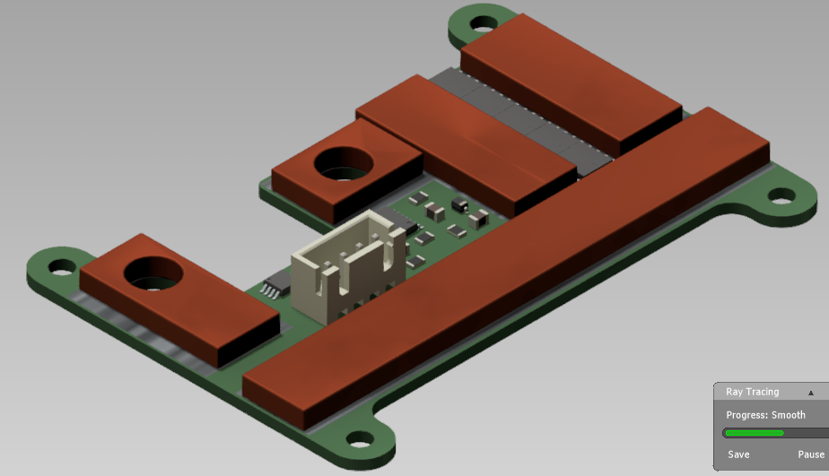
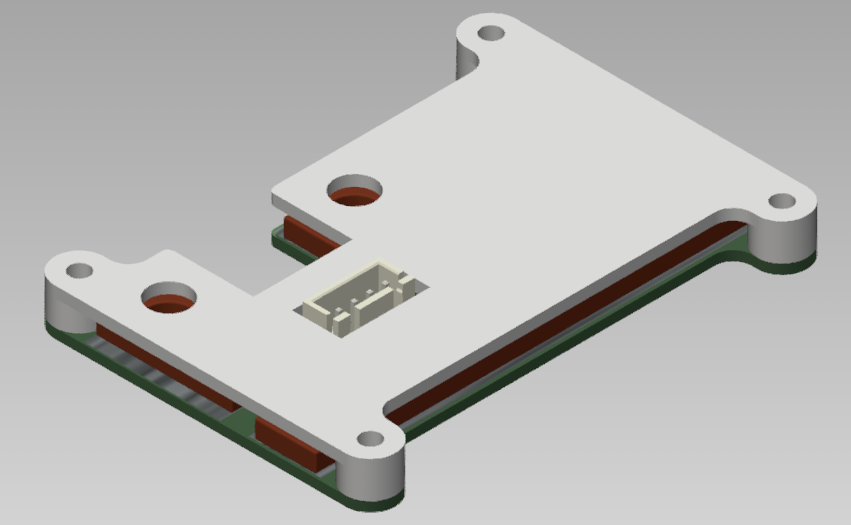
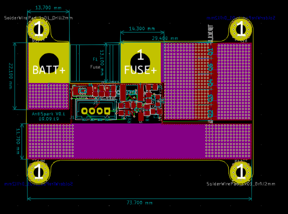
The PCB includes the following features:
| Qty | Value | Footprint | References |
|---|---|---|---|
| 10 | TPW1R306PL,L1Q | SamacSys_Parts:SOP_ADVANCE | Q1, Q2, Q3, Q4, Q5, Q6, Q7, Q8, Q9, Q10 |
| 3 | 1uF | Capacitor_SMD:C_0805_2012Metric_Pad1.15x1.40mm_HandSolder | C1, C4, C5 |
| 2 | 100nF | Capacitor_SMD:C_0805_2012Metric_Pad1.15x1.40mm_HandSolder | C2, C3 |
| 1 | 0 | Resistor_SMD:R_0805_2012Metric_Pad1.15x1.40mm_HandSolder | R2 |
| 1 | 100 | Resistor_SMD:R_0805_2012Metric_Pad1.15x1.40mm_HandSolder | R1 |
| 1 | 10M | Resistor_SMD:R_0805_2012Metric_Pad1.15x1.40mm_HandSolder | R4 |
| 1 | 10k | Resistor_SMD:R_0805_2012Metric_Pad1.15x1.40mm_HandSolder | R6 |
| 1 | 18V | Diode_SMD:D_SOD-323_HandSoldering | D1 |
| 1 | 2M | Resistor_SMD:R_0805_2012Metric_Pad1.15x1.40mm_HandSolder | R3 |
| 1 | 92.301k | Resistor_SMD:R_0805_2012Metric_Pad1.15x1.40mm_HandSolder | R5 |
| 1 | BQ76200PWR | SOP65P640X120-16N | IC1 |
| 1 | Conn_01x04_Male | Connector_JST:JST_XH_B4B-XH-A_1x04_P2.50mm_Vertical | J1 |
| 1 | Fuse | SamacSys_Parts:littleFuseBF1 | F1 |
| 1 | TPS7A4101DGNR | SamacSys_Parts:SOP65P490X110-9N | IC2 |
The 26 most common of 31 parts.
EPFLXplore/XRE_LeggedRobot_HW
PCB designs for Xplore Research's robot dog project

Ricsi1231/BLDC-motor-controller-Hardware---HDI-Desing
EmbedCore motor controller is a high-power brushless motor controller. It was specifically designed to be integrated in Autonomus Mobile Robot wheel actuators. Motor controller can be intagreted to other applications.

aidanbrzezinski/Prism-test
ΛMULET is a high-power brushless motor controller, compatible with the moteus firmware. It was specifically designed to be integrated in EPFL Xplore's Legged Robot actuators.

joeycastillo/Sensor-Watch
A board replacement for the classic Casio F-91W wristwatch

hoglet67/RGBtoHDMI
Bare-metal Raspberry Pi project that provides pixel-perfect sampling of Retro Computer RGB/YUV video and conversion to HDMI

hackclub/OnBoard
💡 Join 1,000 teenagers and make your first PCB with a $100 grant!

openwch/ch32v003
CH32V003 is an ultra-cheap RISC-V MCU with 2KB SRAM, 16KB flash, and up to 18 GPIOs that sells for under $0.10

Luos-io/luos_engine
Open-source and real-time orchestrator for cyber-physical-systems, to easily design, test and deploy embedded applications and digital twins.
It measures 74.5 × 47 mm and has 2 copper layers, 1.6 mm thick.
31 parts, built around the TPW1R306PL,L1Q. The full list of its parts is on this page, with links to each part's symbol and footprint where PCBKit's library has them.
From the VinFar/High-Side-NMOS-Antispark-Switch repository on GitHub, at the commit this page was made from: the board is Anti-Spark.kicad_pcb. PCBKit opens the board in the browser, with nothing to install.
Its repository states no licence, so its author keeps all rights: ask VinFar before reusing the design.