Skip to the content
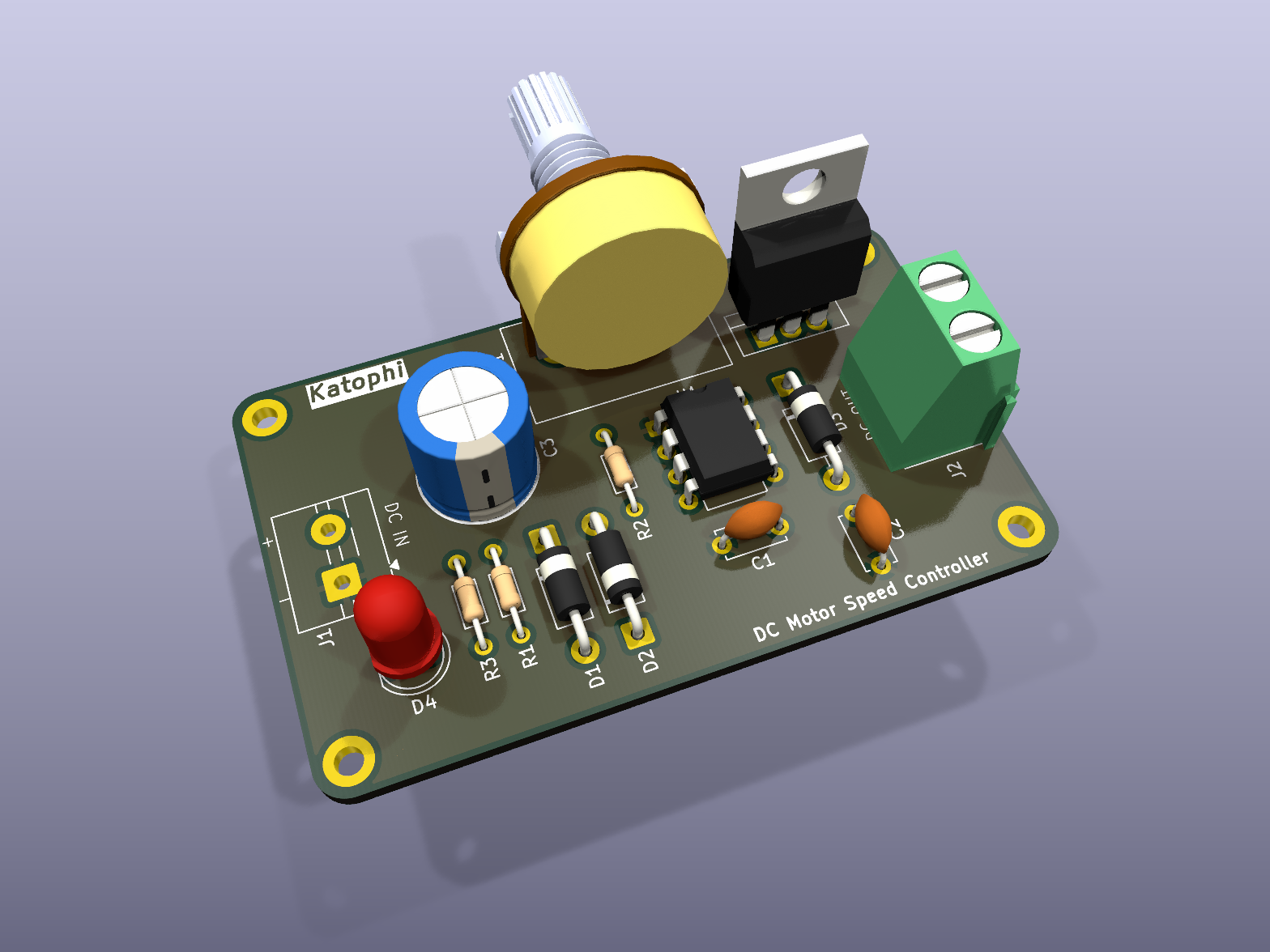
2 layers61.5 × 37.3 mmDC Motor Speed Controller, the printed circuit board in 3D

DC Motor Speed Controller

VikramR3/DC_Motor_Speed_Controller

NE555 PWM speed controller with TIP122 low-side switch - KiCad 9, 2-layer, 61.5 x 37.2 mm

Size
61.5 × 37.3 mm
Copper layers
2
Thickness
1.6 mm
Parts
19
Nets
11
Pads
42
Tracks, vias
67, 0
Pours
1
Routed
Yes
KiCad
KiCad 9.0 (file 20241229)
Created
10 Aug 2026
Updated
16 Aug 2026

Overview

DC Motor Speed Controller is an open-source printed circuit board by VikramR3, from the VikramR3/DC_Motor_Speed_Controller repository on GitHub, published under the MIT licence. It is a 2-layer board of 61.5 × 37.3 mm with 19 parts on 11 nets, routed with 67 tracks and 0 vias.

It is built around the NE555P and TIP122. Its parts include 4 diodes, 3 capacitors, 3 resistors, 2 connectors and 1 IC. It belongs with the robots and motor control boards of this library.

Main components

2

README

README.md

DC Motor Speed Controller

A 2-layer PCB that varies the speed of a brushed DC motor by PWM: an NE555 astable whose duty cycle is set by a 100 kΩ potentiometer, driving a TIP122 Darlington as a low-side switch. Designed in KiCad 9.

DC motor speed controller board

Parts

19
QtyValueFootprintReferences
31N4007Diode_THT:D_DO-41_SOD81_P10.16mm_HorizontalD1, D2, D3
2100nFCapacitor_THT:C_Disc_D5.0mm_W2.5mm_P5.00mmC1, C2
21kResistor_THT:R_Axial_DIN0204_L3.6mm_D1.6mm_P7.62mm_HorizontalR1, R2
2Screw_Terminal_01x02TerminalBlock:TerminalBlock_MaiXu_MX126-5.0-02P_1x02_P5.00mmJ1, J2
11000uFCapacitor_THT:CP_Radial_D10.0mm_P5.00mmC3
1100kPotentiometer_THT:Potentiometer_Alps_RK163_Single_HorizontalRV1
12.2kResistor_THT:R_Axial_DIN0204_L3.6mm_D1.6mm_P7.62mm_HorizontalR3
1LEDLED_THT:LED_D5.0mmD4
1NE555PPackage_DIP:DIP-8_W7.62mmU1
1TIP122Package_TO_SOT_THT:TO-220-3_VerticalQ1

The 15 most common of 19 parts.

Similar boards

  • 2 layers68 × 50.5 mmFanspeed, the printed circuit board in 3D

    Fanspeed

    Aniket95-code/Fan-Speed-Controller-NE555-PCB-design

    A simple, low-cost DC fan speed controller built around the classic NE555 timer IC operating in astable mode. Fan speed is adjusted by varying the PWM duty cycle via a potentiometer, while a TIP122 Darlington transistor…

    19 parts2
  • 2 layersDC motor speed controller, the printed circuit board in 3D

    DC motor speed controller

    arijit-arijit/pcb_design

    my journey in learning to design PCBs from scratch through tutorials and projects

    19 parts1
  • 2 layers65.3 × 33.8 mmDC Motor Speed Controller, the printed circuit board in 3D

    DC Motor Speed Controller

    adityajoshi2008/555-Timer-PWM-DC-Motor-Speed-Controller

    **555 timer-based PWM DC motor speed controller designed and developed in KiCAD for practical motor speed control.

    20 parts
  • 2 layers167.5 × 124 mmMINORAVG, the printed circuit board in 3D

    MINORAVG

    apekg-blip/PWM-based-dc-motor-speed-controller

    Built an analog DC motor speed controller using an NE555 timer IC and LM3914 LED bar graph for duty-cycle visualization. Designed the circuit schematic in KiCad, gaining experience in PWM and analog motor control

    60 parts
  • 2 layers58.3 × 35 mmDC Motor Speed Controller, the printed circuit board in 3D

    DC Motor Speed Controller

    Hirusha785/DC-Motor-Speed-Controller-PCB

    ⚡ NE555 PWM DC motor speed controller PCB designed in KiCad, featuring adjustable speed control, TIP122 driver stage, flyback protection, screw terminals, and 3D PCB renders.

    21 parts
  • 2 layers62.7 × 28.9 mmDC moter speed controller, the printed circuit board in 3D

    DC moter speed controller

    Mahender0408/Embedded-Systems-Projects

    Embedded Systems, IoT and PCB Design Projects

    19 parts
  • 2 layers57 × 32.5 mmDC MOTOR SPEED CONTROLER USING TIMER IC, the printed circuit board in 3D

    DC MOTOR SPEED CONTROLER USING TIMER IC

    MuhammadAbuzarCUI/DC-Motor-Speed-Controller-Using-555-Timer-IC-PCB-Designed-in-KiCad

    PCB design of a DC motor speed controller using the 555 timer IC to generate a PWM signal for speed control. Includes circuit schematic and PCB layout for motor speed regulation by adjusting the PWM duty cycle.

    15 parts
  • 2 layers50.4 × 33.3 mmDC motor speed controller, the printed circuit board in 3D

    DC motor speed controller

    Noraiz963/DC-Motor-Controller

    A 555-timer-based DC motor speed controller designed in KiCad — uses a variable-duty-cycle PWM signal driven through a power transistor to control motor speed with a single potentiometer.

    21 parts

Questions

How big is the DC Motor Speed Controller PCB?

It measures 61.5 × 37.3 mm and has 2 copper layers, 1.6 mm thick.

What parts does the DC Motor Speed Controller use?

19 parts, built around the NE555P and TIP122. The full list of its parts is on this page, with links to each part's symbol and footprint where PCBKit's library has them.

Where can I download the DC Motor Speed Controller KiCad files?

From the VikramR3/DC_Motor_Speed_Controller repository on GitHub, at the commit this page was made from: the board is DC_Motor_Speed_Controller.kicad_pcb and its schematic DC_Motor_Speed_Controller.kicad_sch. PCBKit opens the board in the browser, with nothing to install.

Can I use the DC Motor Speed Controller design in my own project?

Its repository publishes it under the MIT licence: you may reuse it on that licence's terms (keep the author's notice, and for a copyleft licence share your changes alike).