
4 layers103 × 126 mm
Senzori iradiere
cs-pub-ro/smart-solar-irradiance-sensor
Open-source hardware & software for a smart wireless sensor that measures solar irradiance.
351 parts

ESP-IDF 6.0.2 firmware for the custom UWB Module V1.0 Rev.B, based on an ESP32-S3-WROOM-1-N16R8. The same application image runs on every module; persistent identity and runtime configuration select the role and active…
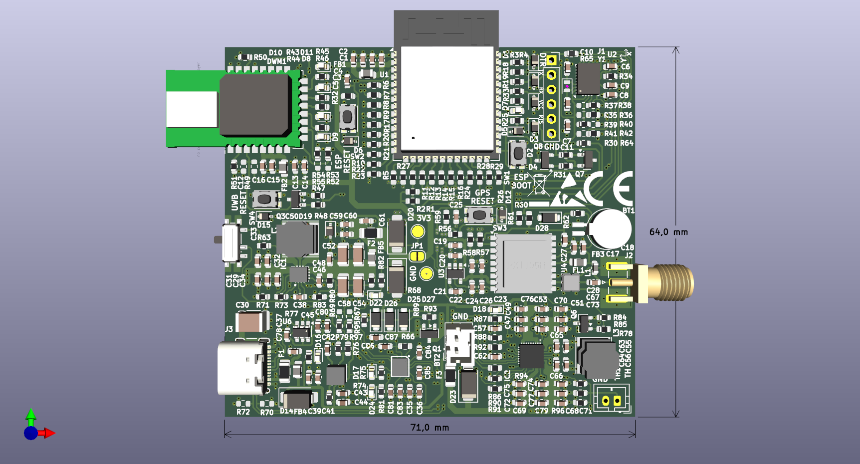
UWB is an open-source printed circuit board by victorstoica114, from the victorstoica114/UWB_Module_ESP_IDF repository on GitHub. It is a 4-layer board of 71 × 64 mm with 254 parts on 193 nets, routed with 2,672 tracks and 584 vias.
It is built around the ESP32-S3-WROOM-1-N8, DWM3000 and MAX77958EWV+T, with the TPS630701RNMT, BNO085 and BQ25792RQMR among its other parts. Its parts include 97 resistors, 85 capacitors, 27 diodes, 9 ICs and 5 transistors. It belongs with the radio and wireless boards and the ESP32 boards of this library.


ESP-IDF 6.0.2 firmware for the custom UWB Module V1.0 Rev.B, based on an ESP32-S3-WROOM-1-N16R8. The same application image runs on every module; persistent identity and runtime configuration select the role and active workflow on each board.
The current firmware combines DW3000 positioning, PX1105R GNSS/RTK, BNO085 IMU telemetry, BQ25792 charging, MAX77958 USB-C Power Delivery, authenticated HTTP OTA/configuration, a browser dashboard, and boot-loop/OTA recovery. The UWB radio runtimes include Native DS-TWR, FlexTDOA, Passive DS-TWR, calibration, survey, distance-test, and beacon diagnostics.
Current firmware defaults, before an NVS override is loaded:
| Setting | Default |
|---|---|
| Runtime | uwb_ranging (Native DS-TWR) |
| UWB | enabled |
| BNO085 | disabled; 2 ms / 500 Hz requested when enabled |
| PX1105R GNSS | disabled |
| BQ25792 monitor | enabled, nominal 1 Hz refresh |
| MAX77958 monitor | enabled, nominal 1 Hz refresh |
| Wi-Fi logs / binary telemetry | enabled |
| Storage | 16 MB flash, dual 4 MB OTA slots, 8 MB octal PSRAM |
Wi-Fi credentials, the OTA token, and optional NTRIP credentials are read from
the Git-ignored secrets.h. Copy secrets.example.h as the starting template.
Non-secret defaults live in components/config; authenticated runtime
overrides are stored in ESP32 NVS.
docs/PASSIVE_DS_TWR.md and
docs/FLEXTDOA_CLEAN_REIMPLEMENTATION.md.PX1105R-firmware/README.md.reports/README.md.mechanical/uwb-gps-enclosure/.This firmware targets the custom UWB Module V1.0 Rev.B hardware.
| Area | Details |
|---|---|
| MCU | ESP32-S3-WROOM-1-N16R8 |
| Flash / PSRAM | 16 MB flash, 8 MB PSRAM |
| USB | Native USB CDC on boot |
| UWB | DW3000/DWM3000 radio path |
| IMU | BNO085 over shared I2C |
| GPS | PX1105R/PX1125R-class GPS path |
| USB-C / PD | MAX77958 |
| Charger | BQ25792 |
| Status LED | GPIO42, active-high |
Active pin mapping lives in components/config/include/board_config.h.
| Function | GPIO |
|---|---|
| Status LED | 42 |
| Shared I2C SDA / SCL | 9 / 10 |
| BNO085 reset / interrupt | 40 / 15 |
| BQ25792 interrupt / QON command / board PG | 4 / 38 / 5 |
| UWB reset / IRQ / CS / wakeup | 8 / 6 / 48 / 7 |
| SPI MOSI / SCK / MISO | 11 / 12 / 13 |
| GPS enable / RX / TX | 47 / 18 / 17 |
| GNSS correction UART TX | 1 |
The DWM3000 data sheet specifies a maximum SPI clock of 38 MHz in mode 0
after OTP boot has completed. ESP32-S3 SPI2 is sourced from the 80 MHz APB
clock and can generate 40 MHz exactly. This project deliberately selects
that divider after field validation on all five modules. It is a documented
2 MHz overclock, guarded by an explicit compile-time opt-in and a separate
38 MHz data-sheet-limit constant so the exception cannot be accidental.
The driver therefore uses two phases:
DEV_ID probe, soft reset, OTP reads, and radio configuration at
4 MHz;40 MHz, after eight
consecutive DEV_ID read-backs succeed.If the operational verification fails, the driver automatically restores the
4 MHz device configuration so the module remains reachable. /status
exposes the effective value as uwb_spi_clock_hz; this is the frequency
reported by the ESP-IDF SPI driver, not only the requested value.
Hardware validation on all five modules, updated 2026-08-05:
| Metric | Result |
|---|---|
| Effective SPI clock, every module | 40 MHz |
| Pure CI-CR validation window | 35 s |
| Selected slot / four-anchor frame | 4.80 ms / 19.20 ms |
| Passive observations | 443-450/s |
| Telemetry drops | 0 |
| Responder-index balance per anchor | typically 37-39 / 37-39 / 37-39 per second |
| Rejected tag observations | typically 0-1/s |
| Incoherent anchor timestamps in stable windows | 0 |
The radio test exercises TX-buffer writes, delayed-TX programming, timestamp
and status reads, and RX-buffer reads. It is therefore a stronger link check
than probing DEV_ID alone.
main/app_main.c only calls app_manager_start(). The application manager
initializes identity and runtime configuration, brings up the recovery/control
plane first, and then starts hardware services and exactly one UWB runtime.
| Component | Responsibility |
|---|---|
app_manager | Boot sequencing, status LED, recovery cutoff, and active-runtime selection. |
config | Board pins, compile-time defaults, persistent module identity/antenna delay, and NVS runtime configuration. |
boot_guard | ESP-IDF OTA validation plus RTC-memory crash-loop detection and recovery mode. |
wifi_service | STA scan, connection, reconnect, BSSID/channel diagnostics, and network status. |
ota_service | HTTP server, /status, OTA, GNSS update staging, and authenticated configuration endpoints. |
wireless_log_service | TCP mirror of ESP-IDF text logs. |
wireless_telemetry_service | Batched UWT1 binary sensor, geometry, range, and position streams. |
resource_monitor_service | Bounded RAM, PSRAM, flash, temperature, and per-core CPU diagnostics. |
i2c_bus_service | Shared BNO085 realtime/BQ25792/MAX77958 background arbitration and optional SCL measurement. |
bno085_service | Interrupt-driven accelerometer and GyroRV acquisition, timestamp reconstruction, recovery, rings, and telemetry. |
charger_service | BQ25792 monitoring, decoded status/ADC data, controlled writes, and NVS-backed charger policy. |
max77958_service | MAX77958 status, AP commands, optional direct-HS I2C, PDO/PPS control, and NVS-backed PD policy. |
gps_service | PX1105R power/UART control, NMEA/SkyTraq parsing, 8 Hz setup, moving-base transport, and NTRIP. |
gnss_firmware_updater | Fixed PX1105R loader/image update sequence using ESP32 PSRAM staging. |
uwb_dw3000 | DW3000 GPIO/SPI/IRQ ownership and all timing-critical UWB runtime loops. |
uwb_ranging_service | Native DS-TWR positioning entry point. |
uwb_distance_test_service | Two-module five-frame diagnostic DS-TWR entry point. |
uwb_calibration_service | Two- and three-module antenna-delay calibration entry point. |
uwb_anchor_survey_service | Anchor-to-anchor survey entry point. |
flextdoa_protocol | FlexTDOA packet codec, collector, and CFO estimator. |
flextdoa_algmin | FlexTDOA frame aggregation and 2D minimization. |
flextdoa_solver_service | Asynchronous embedded FlexTDOA solver and position publication. |
passive_ds_solver_service | Passive DS batching, dynamic geometry, correlated solve, and position publication. |
uwb_mobile_geometry | Converts GNSS anchor positions into a shared local UWB coordinate frame. |
uwb_localization_solver | Generic tested range/range-difference solver library; it is not the owner of a current runtime loop. |
Repository-level supporting material:
| Path | Contents |
|---|---|
tools/ | Build/OTA helpers, dashboard, listeners, capture, replay, calibration, and analysis tools. |
tests/ | Python host tests and standalone C algorithm/protocol tests. |
docs/ | Focused protocol and implementation notes. |
firmware_images/ | Retained ESP32 release inputs, stored through Git LFS where configured. |
PX1105R-firmware/ | Permanent GNSS firmware index and validated ESP32-assisted update artifacts. |
reports/ | Final PDFs plus one self-contained evidence bundle for each report. |
mechanical/uwb-gps-enclosure/ | Parametric V4 enclosure source, reference geometry, print-ready STL files, STEP exports, and previews. |
PCB/V1.REV.B/ | KiCad source, fabrication, BOM, and placement package. |
Schematic/ / datasheets/ | Exported board schematic and local silicon/reference documents. |
reference/ | Migration notes and the intentionally retained legacy GPIO header. |
components/config/include/board_config.h is the active board pin map.
Old GPIO naming is kept only under reference/legacy_headers.
Old legacy project files and cloned third-party repositories are kept local for
inspiration/debugging and are intentionally ignored by Git.
components/config/include/app_config.h holds versioned non-secret application
settings: the default runtime mode, persistent identity provisioning, Wi-Fi
diagnostics/reconnect behavior, wireless-log defaults, OTA-adjacent
service defaults, and optional sensor-test parameters. components/config/include/uwb_config.h
holds UWB-only settings: role, source ID override, antenna delay, beacon
smoke-test parameters, and runtime defaults. Runtime overrides are stored in
NVS through /config/runtime. Keep Wi-Fi credentials and OTA tokens in
secrets.h.
Runtime ownership is intentionally narrow:
main/app_main.c only boots the firmware and calls app_manager_start().components/app_manager/app_manager.c owns what runs on the board and in
what order.app_manager.The current boot sequence is also explicit. app_manager starts the status LED
and boot guard, loads identity/runtime configuration, then brings up Wi-Fi,
wireless logs, binary telemetry, and the HTTP/OTA server. It schedules stable
boot confirmation only after that recovery/control plane is reachable. A normal
boot then starts the resource monitor, optional GNSS, the selected UWB runtime,
BQ25792, MAX77958, and finally the optional BNO085 service. Recovery mode stops
before that second group and holds the DW3000 in reset.
The application task/core split is kept simple so the UWB loop is isolated from most Wi-Fi and TCP work:
| Task / service | Core | Notes |
|---|---|---|
uwb_dw3000 | 1 | Owns DW3000 init, SPI access, RX/TX, ranging, survey, and calibration loops. |
status_led | 1 | Lightweight GPIO blink task. |
boot_guard | unpinned | Confirms stable boots after Wi-Fi/OTA are online and holds recovery state across resets. |
wifi_service | 0 | Owns Wi-Fi STA connect/reconnect management. |
ota_service / httpd | 0 | Starts authenticated OTA, /status, and runtime-config HTTP handling. |
bno085 | 0 | Interrupt-driven BNO085 accelerometer/GyroRV service; owns realtime priority on the shared I2C bus. |
bq25792 | 0 | Low-rate charger monitor; uses background I2C access so BNO085 can win bus arbitration. |
max77958 | 0 | Low-rate USB-C PD monitor/config service; also uses background I2C access. |
gps | 0 | PX1105R power, UART parsing, and moving-base integration when runtime-enabled. |
gps_ntrip | unpinned | Optional single NTRIP caster connection owned by the configured module. |
flex_algmin | 0 | FlexTDOA solver worker, created only by that runtime. |
passive_ds_solver | 0 | Passive DS solver worker with its large stack allocated from PSRAM. |
resource_monitor | 0 | Low-priority bounded resource sampling. |
wireless_log | unpinned | Drains the log queue and mirrors logs over TCP; FreeRTOS may run it on either core. |
wireless_tel | 1 | Drains high-rate telemetry into batched TCP writes. |
| short-lived reboot tasks | unpinned | Temporary restart helpers after OTA or runtime-config changes that explicitly require a reboot. |
ESP-IDF also creates internal Wi-Fi, TCP/IP, and event-loop tasks. The HTTP
server task is pinned to core 0 so /status and runtime config do not share the
UWB core. The timing-critical UWB transmit instants are still programmed into
the DW3000 with delayed TX, so the radio owns the sub-microsecond timing rather
than the FreeRTOS scheduler.
UWB waits are deliberately yielding. RX/TX waits use the DW3000 IRQ line and
FreeRTOS task notifications when IRQ is enabled, with vTaskDelay as the
fallback path. Calibration slot alignment uses the dedicated 1 MHz ESP GPTimer
alarm plus a task notification, so the firmware does not busy-loop while waiting
for the guard window or slot end.
The firmware has two recovery layers so a bad OTA or a crash loop should not make a module disappear from Wi-Fi permanently.
| Layer | What it handles | Mechanism |
|---|---|---|
| ESP-IDF OTA rollback | A new OTA image crashes or resets before it proves it can boot. | CONFIG_BOOTLOADER_APP_ROLLBACK_ENABLE marks a fresh OTA image as pending_verify. The app calls esp_ota_mark_app_valid_cancel_rollback() only after Wi-Fi and OTA HTTP are online for APP_BOOT_GUARD_STABLE_DELAY_MS. If a reset happens first, the bootloader rolls back to the previous valid OTA slot. |
| Local recovery mode | A valid app, serial-flashed app, or bad runtime config keeps rebooting. | components/boot_guard stores a small state record in RTC no-init memory. After APP_BOOT_GUARD_FAILURE_THRESHOLD unstable resets, the next boot starts only identity/runtime config, Wi-Fi, wireless log, telemetry, and OTA. UWB, GPS, charger, USB-C PD, resource monitor, and BNO085 are skipped. |
Normal boot order is intentionally conservative: Wi-Fi, wireless log, telemetry, and OTA start before UWB or I2C peripherals. Recovery mode uses the same path but stops before the risky services and holds the DW3000 in reset.
Task watchdog panic is enabled on purpose. A task watchdog, interrupt watchdog, panic, generic watchdog, or CPU lockup reset is counted as a recovery failure even if the previous boot had already been marked stable. This catches runtime configuration lockups that happen minutes or hours after boot instead of only early boot loops.
/status exposes the recovery state:
| Field | Meaning |
|---|---|
boot_recovery_mode | true when only the minimal recovery services are running. |
boot_guard_failure_count | Consecutive unstable resets counted in RTC memory. |
boot_guard_recovery_threshold | Failure count that latches recovery mode. |
boot_guard_ota_state | Current OTA state, such as valid or pending_verify. |
boot_guard_pending_verify | The running app still needs to be marked valid. |
boot_guard_last_reset_reason_name | Last reset reason reported by ESP-IDF. |
Recovery can be cleared after uploading a known-good firmware or runtime config:
curl -X POST -H "X-OTA-Token: <APP_OTA_PASSWORD>" \
  "http://<module-ip>/config/recovery?clear=1&reboot=1"
Important: rollback lives in the bootloader. OTA updates replace only the app partition, so each module needs one full serial flash after enabling rollback. After that, future OTA images are protected by the rollback flow.
The ESP32 exposes one HTTP control plane after Wi-Fi starts. GET / and
GET /status are intentionally readable without authentication. Every POST
endpoint requires the same header used by OTA:
X-OTA-Token: <APP_OTA_PASSWORD>The password comes from the Git-ignored secrets.h. Configuration values are
passed as URL query parameters even though the method is POST; an empty body
is valid. For example:
curl -X POST -H "X-OTA-Token: <APP_OTA_PASSWORD>" \
"http://<module-ip>/config/runtime?bno085=1&bno085_sample_hz=500"| Method and path | Purpose | Persistence / restart behavior |
|---|---|---|
GET / | Short endpoint and usage summary. | Read-only. |
GET /status | JSON snapshot of identity, boot, UWB, GNSS, IMU, charger, PD, resources, logs, and telemetry. | Read-only. |
POST /ota | Upload an ESP-IDF application image to the inactive OTA slot. | Reboots into the new image; NVS is preserved. |
POST /gnss/loader | Stage the validated PX1105R loader artifact in PSRAM. | Volatile staging step. |
POST /gnss/firmware | Stage the validated PX1105R firmware artifact in PSRAM. | Volatile staging step. |
POST /gnss/firmware/run | Run the fixed GNSS loader/update sequence using the staged artifacts. | Reprograms the GNSS receiver, not the ESP32. |
POST /config/antenna-delay | Stage a calibrated DW3000 antenna delay. | Stored in NVS; applied at radio initialization. |
POST /config/runtime | Change runtime, topology, timing, diagnostics, GNSS, UWB, or BNO085 configuration. | Stored in NVS; some fields apply live or by UWB hot switch, others require reboot=1. |
POST /config/recovery | Clear the local boot-guard latch and optionally reboot. | Updates boot-guard state. |
POST /config/charger | Refresh or configure the BQ25792. | High-level policy is stored in NVS; raw writes are not. |
POST /config/max77958 | Refresh, inspect, or configure MAX77958 USB-C/PD behavior. | Selected high-level policy is stored in NVS; diagnostic operations and raw writes are not. |
Boolean charger/PD parameters accept 1/0, true/false, on/off, and
yes/no. Runtime booleans accept 1/0, true/false, and on/off. Invalid,
out-of-range, incomplete, or unauthenticated requests are rejected; callers
should check both the HTTP status and the JSON response instead of assuming a
write succeeded. The exact BNO085, charger, and PD command tables are in their
respective sections below.
The complete modular V4 enclosure is versioned under
mechanical/uwb-gps-enclosure/. It
includes the CadQuery generator, input reference geometry, validation manifest,
assembly STEP model, rendered previews, and eight print-oriented STL parts.
For printing, use the files ending in _PRINT.stl from
mechanical/uwb-gps-enclosure/exports/.
The enclosure README documents the required inserts, magnets, screws, print
orientation, and assembly order.

The binary CAD, mesh, reference-image, and preview assets are stored through
Git LFS. The source was imported from the validated V4 enclosure revision
7e0be77 of
AlexandruPalacean/uwb-gps-enclosure.
The hardware package is versioned with the firmware so the board definition and software assumptions stay together.
| Path | Purpose |
|---|---|
PCB/V1.REV.B/Kicad project/ | Editable KiCad project and local symbols/footprints |
PCB/V1.REV.B/Gerber/Gerber.zip | Fabrication archive |
PCB/V1.REV.B/BOM/ | BOM exports |
PCB/V1.REV.B/PickAndPlace/ | Assembly placement files |
Schematic/UWB_V1.0_Rev.B.pdf | Exported schematic PDF |
PCB preview:
ESP32 images are published as one GitHub Release per firmware version, ordered
from the oldest retained version to the newest. Each release keeps only the
artifacts needed to install that version; intermediate ESP-IDF build trees are
not release artifacts. The retained source images under firmware_images/ are
tracked with Git LFS.
The release asset names have distinct purposes:
| Asset | Use |
|---|---|
uwb_ota.bin | OTA through POST /ota or tools/ota_upload.py; preserves NVS. |
uwb_full_flash.bin | Complete serial recovery/provisioning image written at offset 0x0; may replace NVS and therefore require identity, runtime, and antenna-delay provisioning again. |
Per-partition .bin files, when present | Low-level ESP-IDF/esptool recovery and diagnosis. Use the offsets documented with that release. |
The current retained ESP32 sequence starts at
firmware-20260804-222730-flextdoa-accuracy and ends at
firmware-20260813-190254-native-uwb-only. Use the
GitHub Releases page
as the canonical download location rather than copying binaries from an old
build directory.
PX1105R firmware is versioned independently so the same GNSS payload is not
duplicated in every ESP32 release. The permanent entry point is
PX1105R-firmware/README.md, which links the
dedicated gps-px1105r-01.07.33 release and records the validated artifacts and
ESP32-assisted update command.
The expected UWB workflow split is:
APP_RUNTIME_MODE_UWB_BEACON_SMOKE: current random beacon TX/RX smoke test
in components/uwb_dw3000.APP_RUNTIME_MODE_UWB_ANTENNA_DELAY_CALIBRATION: antenna delay
calibration entry point in components/uwb_calibration_service.APP_RUNTIME_MODE_UWB_DISTANCE_TEST: current two-module DS-TWR ruler check
entry point in components/uwb_distance_test_service.APP_RUNTIME_MODE_UWB_RANGING: current 4-anchor plus 1-tag DS-TWR
ranging runtime in components/uwb_ranging_service. The first configured
anchor coordinates the slots, anchors initiate, and the tag responds/logs
tag-anchor distances for the dashboard.APP_RUNTIME_MODE_UWB_ANCHOR_SURVEY: anchor-to-anchor survey/runtime
diagnostics in components/uwb_anchor_survey_service.APP_RUNTIME_MODE_UWB_FLEX_TDOA: experimental FlexTDOA runtime. Anchors
rotate as short-slot initiators, continuously refresh live anchor geometry,
and the tag only listens on UWB while sending range-difference observations
to the dashboard over Wi-Fi logs.APP_RUNTIME_MODE_UWB_PASSIVE_DS_TWR: project-specific three-frame
anchor-to-anchor DS-TWR with receive-only tags. It provides independent
Fast Star and Robust Rotating schedules; see
docs/PASSIVE_DS_TWR.md. The surveyed-square
calibration data and 1.89 cm offline RMSE result are preserved in
reports/bundles/passive_ds_known_geometry_20260727.The beacon smoke mode, distance-test mode, antenna-delay calibration workflows, anchor survey, multi-anchor ranging, and experimental FlexTDOA runtimes are implemented for the current lab workflow.
APP_RUNTIME_MODE remains the firmware default. The effective runtime mode and
common test parameters can be overridden at runtime through NVS using the
authenticated /config/runtime HTTP endpoint.
The Position tab switches directly between Native DS-TWR, FlexTDOA, and Passive
DS-TWR through /config/runtime?...&hot_switch=1. A successful hot switch:
The supervisor restores the 4 MHz DW3000 boot SPI rate for the radio reset and returns to the verified datasheet-compliant operational rate after initialization. If radio initialization fails, the firmware falls back to a full ESP32 restart.
Hot switching is deliberately limited to a mode-only transition among these
three positioning runtimes. Changes to module topology, tag/anchor IDs, channel,
radio settings, timing parameters, diagnostics, calibration, or survey modes
still follow the normal reboot path. The /status response exposes
uwb_runtime_switching, uwb_runtime_switch_count, and
uwb_last_runtime_switch_ms so the dashboard can distinguish a short radio
transition from an offline module.
The five-module live test on 2026-07-27 produced:
| Transition | HTTP acknowledgement | All modules UWB-ready | First complete live data |
|---|---|---|---|
| Native DS-TWR -> FlexTDOA | 0.101 s | 0.773 s | 0.784 s |
| FlexTDOA -> Passive DS-TWR | 0.105 s | 0.623 s | 0.932 s |
| Passive DS-TWR -> Native DS-TWR | 0.083 s | 0.764 s | 0.814 s tag ranges; 2.115 s all six anchor pairs |
The measured DW3000 reinitialization time was 449-481 ms. ESP32 boot counters did not change during any transition.
The active ranging implementation is based on Double-Sided Two-Way Ranging
(DS-TWR). Position ranging uses exactly the three native UWB frames: POLL,
RESP, and FINAL.
| Frame | Direction | Purpose |
|---|---|---|
POLL | tag -> anchor | 10-byte protocol header that starts one ranging exchange. |
RESP | anchor -> tag | 10-byte protocol header that provides the responder turnaround. |
FINAL | tag -> anchor | 35 bytes: header plus the tag's POLL TX, RESP RX, and scheduled FINAL TX timestamps. |
The anchor combines the timestamps carried in FINAL with its own POLL RX,
RESP TX, and FINAL RX hardware timestamps and calculates the distance
locally. It reports the result through Wi-Fi, not through an additional UWB
frame. The separate distance-test and calibration runtimes retain their
five-frame diagnostic exchange for bidirectional verification.
The same firmware image runs on every module. At boot, each board reads its persistent module ID and runtime config from NVS.
| Module ID | Normal ranging behavior |
|---|---|
1 | Tag / initiator; ranges each configured anchor in order |
2 | Anchor / responder |
3 | Anchor / responder |
4 | Anchor / responder |
5 | Anchor / responder |
APP_RUNTIME_MODE_UWB_RANGING is tag-initiated. The tag owns the complete
frame schedule and starts one native DS-TWR exchange in every anchor slot.
There is no coordinator, RANGING_CMD, REPORT, or REPORT2. Each responding
anchor calculates the range after FINAL and returns it in a one-shot UWB
RESULT packet. The ESP32 tag solves every coherent four-anchor frame and
publishes the range and raw independent-frame position over Wi-Fi. The
dashboard displays that result and the host tools can independently replay it
for RTK comparison; no temporal position filter is applied.
Native DS protocol version 2 protects every packet with CRC-16/CCITT-FALSE. This application-level CRC also detects payload corruption on the DW3000-to-ESP SPI path after the radio has already accepted the over-the-air frame check.
The tag schedules anchors sequentially:
round N

tag 1 -> anchor 2
tag 1 -> anchor 3
tag 1 -> anchor 4
tag 1 -> anchor 5

wait ranging_round_gap_ms
round N + 1
...
The important timing parameters are exposed by /status, can be changed with
/config/runtime, and are also available in the dashboard:
| Name | Default / lab value | Meaning |
|---|---|---|
ranging_slot_ms | 10 ms | Time budget for one native four-packet exchange. |
ranging_round_gap_ms | 4 ms | Gap after all anchor slots in one frame. |
ranging_rx_slice_ms | 100 ms | RX window used by idle anchor responders. |
ranging_rx_timeout_ms | 5 ms | Maximum wait for the expected RESP, FINAL, or RESULT. |
ranging_resp_delay_ms | 2 ms | Delayed TX offset from POLL RX to RESP TX; also used from FINAL RX to RESULT TX. |
ranging_final_delay_ms | 2 ms | Delayed TX offset from RESP RX to FINAL TX. |
ranging_auto_rx_delay_uus | 500 UUS | DW3000 hardware delay before auto-RX opens after TX. |
These values have their own NVS keys and dashboard profiles. Changing them does
not modify FlexTDOA, distance-test, calibration, or anchor-survey timing. The
tag uses a high-resolution host timer for slot and frame-gap boundaries, so
profiles are not rounded to the 10 ms FreeRTOS tick. Native DS-TWR timing is
copied when its UWB task starts. Timing-only changes can request an in-place
UWB hot switch, which cleanly restarts the radio runtime while Wi-Fi, GPS and
the ESP32 stay online. For four anchors, the default frame is
4 * 10 + 4 = 44 ms.
The selected field profile is a 10 ms slot, 4 ms frame gap, 100 ms idle-anchor
RX slice, 5 ms expected-frame timeout, and 2 ms for each delayed transmission.
In a 180-second channel-9 run it completed 15,138 of 15,183 exchanges
(99.704%), produced 20.82 raw positions/s, and measured 1.80 cm RMSE and
3.07 cm P95 against stabilized RTK, without position filtering. A 42 ms frame
raised throughput to 21.45 positions/s but reduced completion to 99.357%; a
43 ms frame reached 21.12 positions/s at 99.491%. The 44 ms profile is the
recommended robustness/throughput tradeoff. The 64 ms and 100 ms profiles
remain available as intermediate and conservative fallbacks.
APP_RUNTIME_MODE_UWB_FLEX_TDOA is the active pure CI-CR radio protocol with a
radio-passive tag.
The tag does not call any UWB TX function in this mode. It only receives anchor
frames, records its own RX timestamps, feeds the local AlgMin solver, and sends
compact binary range-difference and position telemetry to the dashboard.
FlexTDOA roles are derived from the configured anchor list. Every module in
that list is an anchor; every participating module outside it is a passive tag
and labels telemetry with its own module ID. This permits multiple passive tags
without adding radio slots. An ID must never appear in both Anchor IDs and
Tag IDs; the dashboard rejects that configuration. For example, with five
modules, anchors 2,3,4 can be combined with tags 1,5.
The current firmware is aligned with the FlexTDOA paper at the radio slot level:
one anchor is the initiator in a slot, it broadcasts one request, and K
responders answer in ordered response subslots. With four configured anchors,
K = 3 and a full frame has four initiator slots. The tag remains passive and
derives range-difference observations only from the packets it hears.
With anchors 2,3,4,5, the changing-initiator/changing-responder schedule is:
round 0
  slot 0: A2 requests, responders A3,A4,A5
  slot 1: A3 requests, responders A4,A5,A2
  slot 2: A4 requests, responders A5,A2,A3
  slot 3: A5 requests, responders A2,A3,A4

round 1
  slot 0: A2 requests, responders A4,A5,A3
  slot 1: A3 requests, responders A5,A2,A4
  slot 2: A4 requests, responders A2,A3,A5
  slot 3: A5 requests, responders A3,A4,A2
The responder list rotates from the absolute 32-bit slot ID, slot_id % K.
Consequently both the initiator and the first responder change at every slot,
including between adjacent slots in the same frame. This implements the
paper's CI-CR scheme without holding one response order for an entire frame.
The active FlexTDOA frame set is:
| Frame | Direction | Purpose |
|---|---|---|
FLEX_TDOA_REQ | initiator -> broadcast | Paper request. Carries the 32-bit slot ID, responder count/order, zero processing delay, and one previous TWR result from this initiator. |
FLEX_TDOA_RESP | responder -> broadcast | Paper response. Carries the same slot ID, measured reply delay, and one previous TWR result from this responder. Initiator and responder index are reconstructed from CI-CR plus the source ID. |
Both packet types use the common Figure 3 tail: processing time, previous TWR responder ID, previous TWR distance, and previous measurement slot. The local transport header already carries message type, source ID, and sequence, while the destination list remains variable-length. Every anchor cycles through its own directed TWR cache so a repeatedly refreshed pair cannot starve the other pairs. The parser temporarily accepts the older local request/response layout to keep a parallel OTA rollout operational.
There is no separate coordinator command in the active protocol. After two
seconds of radio silence, the first configured anchor bootstraps slot 0.
Every anchor reconstructs the TDMA phase from valid request packets. Responses
carry the full 32-bit slot ID and can recover a follower that missed the
request; a directly received request remains the authoritative phase reference
for that slot. Each node schedules only its own next initiator slot, and later
requests continually correct local clock drift.
The topology is represented by the same N/K/M parameters used in the paper:
| Field | Meaning | Firmware range |
|---|---|---|
N | Ordered anchor ID list. | 3..10 anchors |
K | Number of responders selected for each request. | 1..N-1 |
M | Number of initiator slots in the repeating frame. | 1..10 slots |
| responder mask | Anchors allowed to respond in one slot; CI-CR rotates the selected K through this pool. | one N-bit mask per slot |
These values are editable under UWB Settings > FlexTDOA Network. Applying a
new topology increments a 32-bit configuration generation and stores it in NVS.
During the three-second startup configuration phase, anchors, the tag, and a
node removed from the new topology can all broadcast their versioned config.
Nodes accept only a newer generation, persist it, and restart their local UWB
state. While the network is running, reception of a newer config causes the
same controlled rebuild. This is the distributed propagation and recovery
path; normal slot synchronization still comes from REQ/RESP, not from a
separate periodic synchronization packet.
The versioned fixed-geometry transport remains for backward compatibility with older captures and deployments. The current positioning workflow clears that legacy state and does not freeze coordinates: live anchor ranges continuously drive the embedded and dashboard geometry solvers.
The CI-CR slot keeps the structure of equation (20) from the paper. Its timing terms are runtime parameters persisted in NVS and propagated over UWB, so each tested combination is kept as a named frame-length profile in the dashboard:
t_slot = guard + request_subslot + request_process
       + K * response_subslot
       + K * response_process_per_responder
For four anchors, K = 3, the dashboard exposes the two field-validated
profiles plus the exact equation (20) paper reference:
| Profile | Guard | REQ | Process REQ | 3 x RESP | 3 x Process RESP | Slot | Frame | Frame rate |
|---|---|---|---|---|---|---|---|---|
32.20 ms Field Fast | 250 us | 2000 us | 250 us | 2550 us | 3000 us | 8.050 ms | 32.200 ms | 31.06 Hz |
34.00 ms Field Stable | 250 us | 2000 us | 250 us | 3000 us | 3000 us | 8.500 ms | 34.000 ms | 29.41 Hz |
20.20 ms Paper Reference | 250 us | 2000 us | 250 us | 750 us | 1800 us | 5.050 ms | 20.200 ms | 49.50 Hz |
32.20 ms Field Fast is the firmware default. A clean 120 s channel-9 run on
all five deployed modules produced 30.02 independent positions/s, 2.924%
effective slot loss, zero new delayed-TX errors, 2.03 cm RMSE and 3.58 cm
P95 against the static RTK reference, with no position filter. The
34.00 ms Field Stable profile remains available as the conservative control.
The paper reference is kept exact for protocol comparison, but its 250 us
response spacing does not provide enough margin for the complete ESP32-S3
field workload.
For the selected field profile, one slot is:
250 + 2000 + 250 + 3*850 + 3*1000 = 8050 usThe selected responder transmits using DW3000 delayed TX from the request RX timestamp. For the selected field profile:
RESP[0] = REQ_RX + 2250 us
RESP[1] = REQ_RX + 3100 us
RESP[2] = REQ_RX + 3950 us

four-anchor frame = 4 * 8050 us = 32.20 ms
frame rate        = 31.06 frames/s theoretical
measured rate     = 30.02 complete positions/s
The responder does not read SYS_TIME to turn that relative delay into an
absolute radio timestamp. It combines the already-read request RX timestamp
with the relative delay, writes that target to DX_TIME, and issues the native
DW3000 CMD_DTX fast command. The reply interval
carried in FLEX_TDOA_RESP is derived from the same quantized delayed-TX target,
including TX antenna delay, so the tag subtracts the interval that the radio
actually used rather than an ideal host-side delay.
FlexTDOA RX timestamps also avoid a per-frame SYS_TIME reference. The DW3000
double-buffer diagnostic set exposes the low 32 bits of RX_TIME reliably, and
adjacent FlexTDOA packets are much closer than the approximately 67 ms wrap
period of those 32 bits. Firmware therefore extends each low word from the
previous RX timestamp by signed continuity. A hardware diagnostic run found
that the nominal fifth timestamp byte in the buffered metadata was occasionally
incoherent (21 mismatches in about 18,975 comparisons on M1), so trusting
that byte directly would be less robust than continuity.
One SYS_TIME read seeds the 40-bit epoch when the first FlexTDOA packet is
received. A new seed is used only as a recovery action after more than 30 ms
without a received packet, where low-word continuity would become ambiguous.
There is no periodic or per-frame SYS_TIME read in the continuous FlexTDOA
path. Full SYS_TIME reads remain in generic DS-TWR timestamp reconstruction
and delayed-TX failure diagnostics; they are not part of the normal FlexTDOA
slot.
The request RX timestamp marks the radio timing reference near the beginning of
the received frame. The field profile reserves a 2000 us request subslot and
a 250 us request-processing term before the first response. Together they
cover packet airtime, SPI decode, RX double-buffer release, and delayed-TX
arming. K * response_process is the paper's
aggregate response-processing budget, not extra spacing between responses.
The configured quiet guard ends the slot before the next request.
For a slot where A3 is the initiator:
A3 initiator                  A4/A5/A2 responders             passive tag
 t=0.00 ms  REQ ------------------------>|------------------------> RX REQ
 t=2.25 ms  <---------------- RESP[0] A4 |------------------------> RX RESP
 t=3.10 ms  <---------------- RESP[1] A5 |------------------------> RX RESP
 t=3.95 ms  <---------------- RESP[2] A2 |------------------------> RX RESP
 t=8.05 ms  next initiator request ------|------------------------> next slot
The ESP task wakes before its own next request and programs delayed TX. This
preparation lead is local only and adds no airtime. A longer 5000 us lead was
rejected in hardware tests because it stopped reception before the preceding
slot completed. Delayed responses use the processing budget selected by the
active profile; a rejected or late command is reported explicitly instead of
leaking into the next slot.
The passive tag computes the paper TDOA observation:
diff_dtu = (RESP_RX_tag - REQ_RX_tag)
         - responder_reply_dtu_corrected
         - anchor_anchor_tof_dtu
responder_reply_dtu_corrected uses the instantaneous DW3000
carrier-integrator clock ratio from that response. anchor_anchor_tof_dtu
comes from the cached
anchor-anchor distance learned from the Figure 3 piggyback stream. The latest
directed measurement of either orientation is used until the pair has a newer
value.
No median, moving average, or position filter is applied to the passive tag's
FlexTDOA observations in firmware. Firmware only rejects structurally invalid
observations: mismatched slot_id/responder index, missing CIA clock data, or
an RX timestamp outside the current slot. Position solving and any future
estimator are deliberately kept outside this radio validation.
| Paper requirement | Firmware state |
|---|---|
| Passive DL-TDOA tag | Implemented. The tag only receives FLEX_TDOA_REQ/RESP. |
One request and K responses per slot | Implemented. The exact paper profile uses 250 us response spacing; the field default uses the validated 850 us response spacing with 2000 us REQ, 250 us request processing, 1000 us response processing, and 250 us guard terms. |
| Request carries responder count/list/order | Implemented in FLEX_TDOA_REQ. |
| Every localization packet carries 32-bit slot ID | Implemented in every request and response. This avoids the 256-slot wrap ambiguity of an 8-bit counter. |
| CI-CR schedule | Implemented by rotating initiator and responder order every slot/round. |
| CFO-based reply delay correction | Implemented from buffered CIA_DIAG_0, with the Qorvo sign convention and no clock Kalman filter. |
| Anchor self-localization payload | Implemented. Each request and response carries one previous directed SS-TWR+CFO result using the Figure 3 fields. |
| Fully distributed slot synchronization | Implemented from request RX timestamps. A response can recover a node that missed the request, but a directly received request is authoritative for that slot. |
General N/K/M topology | Implemented for 3..10 anchors, configurable responder count, initiator slots, and per-slot responder masks. |
| Configuration propagation | Implemented as versioned UWB frames. Topology is persisted and rebroadcast during startup; the legacy fixed-geometry generation is cleared for live positioning. |
| Local solver | Implemented on the tag ESP32-S3. It continuously reconstructs relative geometry from fresh anchor TWR ranges. Raw TDOA observations feed a damped 2D least-squares AlgMin service on core 0; UWB remains on core 1. |
| Radio setup | The field deployment uses CH9 and the validated PHY2 profile. CH5, 6.8 Mb/s, PRF 64 MHz, preamble 128 remains the paper-reference setup. |
| Firmware-side measurement filters | None. The radio path emits every structurally valid raw anchor range and tag range difference. |
The local solver is the planar specialization needed by the present hardware layout. The paper evaluates 3D AlgMin and AlgEKF as well. Therefore the radio protocol and AlgMin objective are aligned, but the current embedded solver is not a general 3D replacement for every solver variant in the paper.
The paper's node uses an STM32F429ZIT6: Cortex-M4 with FPU at 168 MHz, 2 MB
Flash, and 256 KB SRAM. That MCU has excellent deterministic interrupt
latency, but it is not more powerful overall than this dual-core ESP32-S3 at
240 MHz with external PSRAM. The practical difference is workload isolation:
Wi-Fi and HTTP share the ESP32-S3, so the timing-critical UWB path is pinned to
core 1 and the local solver runs on core 0.
The local solver removes the PC/network round trip from the positioning path;
it does not shorten radio airtime. With M=4, one solution can be published
after every 32.20 ms complete field frame. The validated deployment produced
30.02 independent solutions/s.
The dashboard prefers this ESP32 AlgMin result while it is fresh and falls
back to its PC solver only when local position telemetry is unavailable.
The iterative position solve follows the first-order Taylor linearization and
least-squares refinement described in the local
datasheets/GPS-Compendium_Book_(GPS-X-02007).pdf, sections 6.2.2-6.2.4.
The previous valid position is the normal warm start; the anchor centroid is
retained as a recovery candidate. The GPS compendium notes that a good initial
estimate normally converges in roughly three to five iterations. On the live
FlexTDOA stream, the embedded solver needed only 2.09 iterations on average,
while retaining the six-iteration ceiling for recovery from a poor initial
estimate.
The ESP32-S3 position hot path now builds one compact set of fresh TDOA observations per solution and uses hardware-accelerated single-precision math. It no longer scans the complete observation matrix for every cost evaluation. The least-squares objective, centroid comparison, Levenberg-style damping, step bound, line search, convergence threshold, and reported uncertainty are unchanged. Anchor self-localization remains double precision and is measured separately.
Static hardware measurements on M1, with four live anchors and the same raw FlexTDOA stream, gave:
| Metric | Original solver | Optimized solver |
|---|---|---|
| Solutions per second | 68.0 | 67.9 |
| Average position solve | 5.88 ms | 0.89 ms |
| Average AlgMin iterations | not instrumented | 2.09 |
| Average cost evaluations | not instrumented | 9.66 |
| Solver queue depth, sampled each second | 16.4 average | 5.9 average |
| Solver queue maximum in the test | 94 | 53 |
Queue drops in the final 90 s run | present | 0 |
| M1 core 0 load | approximately 67% | approximately 41.5% |
The optimized and original 15-second stationary captures remained comparable:
position standard deviation changed from 4.47/3.18 cm on X/Y to
4.23/3.18 cm, and RMS residual changed from 9.65 cm to 10.16 cm.
Those differences are within the changing live radio observations and do not
indicate added filtering; every structurally valid raw observation still feeds
the solver. Measured wall-time maxima include preemption by Wi-Fi and other
core-0 work, so they are diagnostic scheduling latency rather than the normal
AlgMin compute time.
Local position telemetry has a dedicated Server-Sent Events endpoint. The
dashboard records every received position immediately and schedules the newest
one for the next browser animation frame. The heavier status, geometry, and
diagnostic tables remain on the 250 ms snapshot poll. This separates radio
and solver throughput from browser repaint rate: an 83.33 Hz position stream
can be received completely on a display that can draw only about 60 fps.
A two-minute hardware run with all five modules and the 12.00 ms Frame
profile measured:
| Metric | Result |
|---|---|
| Nominal local solution rate | 83.33/s |
| Positions received by the SSE server | 9,971 |
| Measured SSE rate | 83.333/s |
| Unique position event IDs | 9,971 |
| Browser rate, headless 60 Hz display | 83 rx/s, approximately 55 fps |
| Median server delivery age | 1.67 ms |
| Telemetry drops | 0 on all five modules |
| Anchor transmissions | 160,170 |
| Anchor TX errors | 9 (0.0056%) |
| M1 telemetry queue high-water mark | 1,024/1,024, without drops |
| M1 peak core load during the run | core 0 63.2%, core 1 85.2% |
The exact average output rate proves that the optimized solver and dashboard
can sustain the 83.33 Hz experiment. Rare delayed-TX rejects, one long
delivery interval, and the full M1 telemetry queue also confirm that this is a
limit test with little scheduling reserve. The 14.80 ms Frame profile remains
the robust default until the shorter timing receives a longer clean run.
HTTP status polling is performed concurrently for all modules. A single failed
poll marks the last status as degraded but does not immediately hide a live
position; the module becomes offline only after its last successful status has
aged out. High-rate accelerometer samples are fetched and decoded by the
browser only while the Graphs tab is visible, while the server continues to
receive and buffer them.
A coexistence check with the 14.80 ms Frame profile and all five BNO085
sensors at 500 Hz saturated M1's telemetry queue and added 1,522 drops in
one minute. After disabling the accelerometers without rebooting, the queue
drained and the drop counter remained unchanged for the following 30 s.
Maximum-rate FlexTDOA measurements should therefore keep BNO085 disabled;
running both at maximum rate remains a separate telemetry coexistence stress
case.
Before compacting the request and guard budgets, the complete implementation was exercised on five physical modules: four anchors and one radio-passive tag. The final image ran for more than three minutes with all nodes HTTP-online, no watchdog reset, no panic, and no queue drop. One isolated late slot was reported and the affected anchor recovered from subsequent radio traffic without restarting the network.
| Metric | Measured | Theoretical / interpretation |
|---|---|---|
| Slot duration | 5.05 ms | Equation (20) timing used by this baseline test. |
| Frame duration | 20.20 ms | Four initiator slots. |
| Anchor results | usually 141-148/s per anchor | Maximum 148.5/s from three responses in each own slot. |
| Passive-tag observations | usually 470-525/s | Maximum 594.1/s; the remaining loss is in the very tight 250 us receive train. |
| RX double-buffer release | usually 198-216 us maximum per one-second summary | Fits inside one response subslot, with limited margin. |
| Local position | one result per complete frame | Approximately 49.5 AlgMin solutions/s. |
| Tag CPU load | about 48% on core 0 and 48% on core 1 | Solver on core 0, UWB receive path on core 1. |
| Anchor CPU load | about 5-8% on core 0 and 23-24% on core 1 | No local tag-position solve. |
The DW3000 does not support RXAUTR together with receive double buffering.
The fast path therefore issues CMD_RX immediately after a good frame, before
copying the occupied buffer. It releases that buffer by clearing only its RDB
status and RX-good SYS_STATUS events, then issuing CMD_DB_TOGGLE. It does
not use global CMD_CLR_IRQS, which can erase unrelated TX state. Expected PHY
errors are accumulated into the one-second summary instead of synchronously
formatting UART warnings from the timing-critical UWB task.
Recovery was also tested by rebooting only M4. Its boot counter advanced once,
it restored generation 3 (N=4, K=3, M=4) from NVS, learned the current
TDMA phase from live FlexTDOA traffic, and resumed increasing TX/RX counters.
The other four nodes were not restarted.
On 2026-07-22, the compact profile was applied to all five physical modules and
persisted as runtime configuration generation 6. Every module restored the
same five timing values after the requested reboot:
guard=250 us, REQ=250 us, process REQ=1250 us,
RESP=250 us, process RESP=400 us per responder
For N=4, K=3, and M=4, this produces a 3.700 ms slot, a 14.800 ms
frame, 67.57 frames/s, and 810.8 scheduled responses/s. A monotonic-counter
window taken after boot stabilization produced:
| Metric | 60 s result |
|---|---|
| Anchor TX count | 16,343-16,352 per module |
| TX errors | 0 on all five modules |
| RX error ratio | 0.13-0.26% |
| Protocol queue drops | 0 |
| Incoherent anchor observations | 0 |
| Measured REQ processing path maximum | below 460 us |
This is a successful compact-profile trial, not yet a replacement for the
longer 150 s validation of the conservative profile. Longer runs and dynamic
tag tests should be added under the same frame-length profile name so timing
results remain directly comparable.
The profiles below were exercised consecutively on all five physical modules
on 2026-07-22. Each short profile was observed for 30 s; the restored
14.80 ms profile received a separate clean 60 s steady-state window after
the simultaneous reboot and network resynchronization had settled.
| Frame | Slot | Frame rate | Response rate | Hardware result |
|---|---|---|---|---|
14.80 ms | 3.70 ms | 67.57 Hz | 810.8/s | Recommended: 0 TX errors in the clean 60 s window. |
14.20 ms | 3.55 ms | 70.42 Hz | 845.1/s | Borderline: 1 delayed-TX reject and resynchronization in 30 s. |
13.60 ms | 3.40 ms | 73.53 Hz | 882.4/s | Borderline: 1 delayed-TX reject and resynchronization in 30 s. |
12.60 ms | 3.15 ms | 79.37 Hz | 952.4/s | Failed: 2 delayed-TX rejects and resynchronizations in 30 s. |
12.00 ms | 3.00 ms | 83.33 Hz | 1000.0/s | Failed: 3 TX failures in 30 s. |
The instrumentation separates delayed-TX register programming from the full
radio path. Request arming normally peaked at approximately 90-153 us, while
the observed response hot path remained below approximately 480 us. Those
averages and ordinary maxima do not define the safe timing margin: the failed
profiles expose rare millisecond-scale task and radio-state stalls.
An ESP timer ISR dispatch experiment reduced some late request scheduling, but
it could wake the same UWB task while that task was waiting for a response TX
event and introduced occasional response-path failures. It was rejected. The
firmware was restored to the original task-dispatched timer and fixed
1750 us request preparation lead before the final clean 14.80 ms run.
The runtime is limited by worst-case host/radio turnaround rather than the
6.8 Mbps UWB PHY. DW3000 SPI requests and runs at the field-validated
40 MHz ESP32-S3 divider. This intentionally exceeds the data-sheet limit of
38 MHz, as documented in the hardware section above. The hot
path uses polling SPI, compact payload/metadata reads, targeted RX status
clears plus DB_TOGGLE, cached TX_FCTRL, early request-buffer release, and
DW3000 delayed TX.
validated ESP32-S3 slot, K=3 = 4.80 ms
four-anchor frame            = 19.20 ms
theoretical frame rate       = 52.08/s
theoretical response rate    = 625.00/s
The measured REQ-to-CMD_DTX software path is normally about 230-250 us
and stayed below 500 us in the final run. That is not itself a safe protocol
budget: the DW3000 also needs a valid radio state and enough future lead when
the delayed command is accepted. Hardware tests established the following
margin boundary:
| REQ processing budget | RX release / delayed-TX order | Hardware result |
|---|---|---|
500 us | release before CMD_DTX | Repeated delayed-TX rejects and timeouts. |
500 us | CMD_DTX before release | Faster measured host path, but DB_TOGGLE could cancel the pending delayed TX and responder counts became unbalanced. Rejected. |
600-650 us | release before CMD_DTX | Intermittent failures remained. |
750 us | release before CMD_DTX | Rare missed TX/state errors remained during longer runs. |
1500 us | release before CMD_DTX | Validated: 150 s steady operation with no delayed-TX timeout/reject/state error, no missed slot, no response failure, and balanced 52/52/52 responder counts per anchor summary. |
The safe order is therefore fixed: release the processed RX double buffer
before arming delayed TX. A one-time cluster can still appear about 31 s
after a newly installed image boots, when the boot guard validates the OTA
image and writes flash. The subsequent steady-state radio test was clean; that
flash-write disturbance is separate from the FlexTDOA timing margin.
The following table is a historical optimization record from 2026-07-18. Its rows precede the final exact-paper timing and used the moved module layout. It must not be read as the current configuration or as a geometry/accuracy test.
| request process | response subslot | tag valid/s | anchor results/s/module | responder-index balance | result |
|---|---|---|---|---|---|
1000 us | 250 us | 407-446 | 128-131 | nearly balanced | About 70-105/s tag timestamps were outside the slot. |
1000 us | 300 us | 491-497 | 111-117 | middle index low | Tag improved, but initiators still lost middle-buffer timestamps. |
1500 us | 300 us | 452-458 | 106-112 | middle index low | More TX margin did not repair the double-buffer boundary. |
1500 us | 350 us | 443-450 | 113-114 | typically 37-39 per index | Initial selected run before removing synchronous UART work from the radio task. |
1500 us | 350 us | 451-456, avg 454.1 | avg 113.8-114.0 | normally 38,38,38 | Final relative-radio path over 41 s: zero drops, delayed-TX misses, response failures, and TX-interval mismatches. |
The selected historical 1500/350 us rate was within 0.1% of its
454.55/s theoretical tag rate. Across that 41 s window, the tag rejected 14 of roughly 18,600
observations (0.08%) and anchors marked 5 of roughly 18,700 results
incoherent (0.03%); all telemetry drop counters remained zero. The one-second
diagnostic summaries are submitted directly to the wireless log queue. They do
not pass through synchronous UART formatting in the timing-critical UWB task,
which previously created a delayed-TX miss approximately once per second.
Historical slot-order scenarios:
| Scenario | Directed slot order | Pair reverse separation | Full directed cycle | Read |
|---|---|---|---|---|
| Previous round-reverse | 2->3, 2->4, 2->5, 3->4, 3->5, 4->5, then all reversed next round | 6 * slot + gap | 12 * slot + 2 * gap | Good for sweeping all pairs, but each paired TDOA observation mixes directions separated by most of a round. |
| DS-TWR adjacent pair round-trip | 2->3, 3->2, 2->4, 4->2, ... | 1 * slot | 12 * slot + gap | Previous practical hybrid: stable anchor geometry, slower tag updates. |
| Paper-style FlexTDOA | one request, K responders in subslots | within one frame | N * slot + gap | Current FlexTDOA runtime. Faster and matches the paper's CI-CR slot model. |
Legacy hybrid static speed test, 2026-07-16:
The modules were in the temporary charging-room geometry, so this test should be
read as a timing/robustness run, not as an absolute-location accuracy run. The
tag was left static and the dashboard log stream was sampled after each profile
change. This table belongs to the previous DS-TWR-based hybrid, not to the
paper-aligned FlexTDOA runtime above. obs Hz counts passive tag observations,
observed cycle is inferred from those observations for a 12-directed-slot
four-anchor cycle, fresh pairs is the number of paired TDOA observations
available to the solver at the end of the run, and rev p90 is the 90th
percentile of abs(Ai->Aj + Aj->Ai).
| Profile | slot | command | RESP | FINAL | REPORT | timeout | run | fail | fresh pairs | obs Hz | observed cycle | rev p90 | anchor std med | Read |
|---|---|---|---|---|---|---|---|---|---|---|---|---|---|---|
| Stable baseline | 100 ms | 10 ms | 20 ms | 20 ms | 10 ms | 90 ms | 30 s | 0 | 5/6 | 8.06 | 1.49 s | 96.0 cm | 0.55 cm | Robust, but slower and missed one fresh pair in this geometry. |
| Safe Fast preset | 60 ms | 5 ms | 15 ms | 15 ms | 5 ms | 35 ms | 30 s | 36 | 1/6 | 8.36 | 1.44 s | 32.2 cm | 0.46 cm | Too short; mostly RESP wait failed. |
| Balanced preset | 50 ms | 5 ms | 10 ms | 10 ms | 5 ms | 25 ms | 30 s | 63 | 1/6 | 9.79 | 1.23 s | 35.2 cm | 0.83 cm | Faster observations, but not robust. |
| Aggressive preset | 40 ms | 3 ms | 7 ms | 7 ms | 3 ms | 18 ms | 30 s | 142 | 2/6 | 10.89 | 1.10 s | 45.2 cm | 0.54 cm | Beyond the current reliable DS-TWR limit. |
| Reduced-delay 90 | 90 ms | 5 ms | 15 ms | 15 ms | 5 ms | 80 ms | 60 s | 0 | 6/6 | 9.10 | 1.32 s | 64.9 cm | 0.68 cm | Best fast candidate in this run. |
| Reduced-delay 100 | 100 ms | 5 ms | 15 ms | 15 ms | 5 ms | 90 ms | 60 s | 0 | 6/6 | 8.87 | 1.35 s | 102.3 cm | 0.71 cm | Safest current operational profile; similar speed to 90 ms with more slot margin. |
The main conclusion from that older branch was that full DS-TWR slots were
robust but expensive. That pushed the current branch toward the paper-style
FlexTDOA slot above: one request, ordered response subslots, and a passive tag
that does not need the full POLL/RESP/FINAL/REPORT/REPORT2 exchange.
Every localization packet carries the full 32-bit slot counter. The counter is part of the deterministic initiator/responder ordering used by every anchor. An earlier experiment carried only the low byte; after 256 slots that could make a recovering follower infer a different response order. Keeping all 32 bits is cheap and removes that long-run ambiguity.
The dashboard consumes tag observations coherently by slot ID instead of mixing fresh-looking rows from unrelated slots. Anchor ranges also carry the full 32-bit slot ID. The dashboard groups all pair ranges from one complete TDMA frame and performs one multi-range EKF update, matching the paper's anchor self-localization procedure.
The anchor EKF uses the paper's published covariance values:
anchor model variance      sigma_Q^2 = 1 cm^2
TWR measurement variance  sigma_R^2 = 10 cm^2
The dashboard treats the resulting covariance and the geometric fit as two different quantities. A small EKF covariance does not prove that the nonlinear solver selected the correct geometric minimum. The RMS error between the EKF coordinates and the current complete TWR frame is compared with three measurement standard deviations:
fit reference = 3 * sqrt(10 cm^2) = 9.49 cm RMSThis is a solver diagnostic, not a filter applied to the raw FlexTDOA or TWR
observations. Positioning no longer waits for an operator to freeze geometry.
The EKF keeps updating while the protocol runs. Three newly updated geometry
batches above 25 cm RMS trigger an automatic geometric reinitialization, so a
physically relocated anchor is acquired instead of being treated as a
permanent residual. Reset Live Geometry Estimate remains available for a
manual recovery and also clears any legacy fixed generation from the modules.
For the current planar setup, the paper's coordinate convention is adapted to
2D: the first selected anchor is fixed at (0,0), the second is on the positive
Y axis, and the third has positive X. This removes the unobservable global
translation, rotation, and mirror ambiguity while allowing every relative
anchor coordinate to change continuously. Geometry sessions are kept separate
per radio protocol so protocol-specific range bias is not mixed when the
operator switches solvers. There is no median window or automatic freeze in
this path.
Each new least-squares tag solve is seeded from the previous valid tag position, as described for AlgMin in the paper. This selects the same physical solution branch but does not average or smooth tag measurements.
The initiator also refreshes live anchor geometry from the request/response
exchange in the same slot. This is the short TWR measurement described by the
paper as anchor self-localization payload, not the older full DS-TWR
POLL/RESP/FINAL/REPORT/REPORT2 sequence:
round = RESP_RX_initiator - REQ_TX_initiator
reply = RESP_TX_responder - REQ_RX_responder

tof = (round - reply_corrected) / 2

anchor_distance = c * tof
That distance is cached as an unordered anchor pair and emitted to the dashboard with its 32-bit slot ID. No rolling median is applied. The anchor EKF only updates when a complete coherent frame contains every selected pair.
Lab stability comparison, 2026-07-15:
This test compares anchor-anchor range stability only, not absolute placement
accuracy. The modules were left in the current room/charging layout, so the
important number is short-term spread, not whether the measured edge length is a
known physical value. The FlexTDOA run used the short REQ/RESP anchor
measurement used by the earlier clean FlexTDOA prototype. sample is the
unfiltered corrected single-shot value from that short-anchor prototype. The
median9 rows are historical offline/firmware comparisons only; the current
FlexTDOA runtime no longer applies them. The DS-TWR run used
APP_RUNTIME_MODE_UWB_ANCHOR_SURVEY, which performs the full
POLL/RESP/FINAL/REPORT/REPORT2 exchange. This result explains why the legacy
hybrid geometry looked so stable, while the current FlexTDOA runtime
intentionally keeps the shorter paper-style request/response geometry path and
shows raw behavior.
| Protocol/value | Pair | n | avg cm | median cm | min cm | max cm | std cm | span cm |
|---|---|---|---|---|---|---|---|---|
FlexTDOA sample raw | 2-3 | 221 | 547.3 | 548.5 | 486.1 | 593.5 | 14.9 | 107.4 |
FlexTDOA sample raw | 2-4 | 236 | 563.9 | 563.9 | 503.4 | 668.7 | 17.1 | 165.3 |
FlexTDOA sample raw | 2-5 | 243 | 862.6 | 864.9 | 747.2 | 957.1 | 18.2 | 209.9 |
FlexTDOA sample raw | 3-4 | 257 | 827.9 | 829.2 | 763.0 | 881.0 | 14.5 | 118.0 |
FlexTDOA sample raw | 3-5 | 274 | 733.4 | 735.7 | 650.0 | 834.5 | 21.1 | 184.5 |
FlexTDOA sample raw | 4-5 | 275 | 552.1 | 552.5 | 477.0 | 664.6 | 21.1 | 187.6 |
FlexTDOA median9 | 2-3 | 221 | 548.3 | 548.5 | 546.3 | 552.2 | 0.8 | 5.9 |
FlexTDOA median9 | 2-4 | 236 | 566.0 | 566.0 | 562.2 | 568.3 | 0.4 | 6.1 |
FlexTDOA median9 | 2-5 | 243 | 865.5 | 865.5 | 853.5 | 873.4 | 1.0 | 19.9 |
FlexTDOA median9 | 3-4 | 257 | 829.4 | 829.4 | 827.8 | 832.5 | 0.3 | 4.7 |
FlexTDOA median9 | 3-5 | 274 | 732.5 | 732.5 | 713.0 | 745.1 | 2.7 | 32.1 |
FlexTDOA median9 | 4-5 | 275 | 551.2 | 551.1 | 528.5 | 559.5 | 2.2 | 31.0 |
| DS-TWR survey raw | 2-3 | 98 | 549.4 | 549.4 | 547.5 | 551.1 | 0.8 | 3.6 |
| DS-TWR survey raw | 2-4 | 98 | 564.2 | 564.2 | 560.3 | 567.1 | 1.5 | 6.8 |
| DS-TWR survey raw | 2-5 | 99 | 867.5 | 867.2 | 862.9 | 872.3 | 2.1 | 9.4 |
| DS-TWR survey raw | 3-4 | 98 | 830.7 | 830.8 | 829.1 | 832.7 | 0.7 | 3.6 |
| DS-TWR survey raw | 3-5 | 99 | 737.1 | 737.3 | 732.8 | 740.1 | 1.5 | 7.3 |
| DS-TWR survey raw | 4-5 | 78 | 551.6 | 551.7 | 548.1 | 554.6 | 1.5 | 6.5 |
DS-TWR median9 | 2-3 | 98 | 549.4 | 549.4 | 548.3 | 550.4 | 0.4 | 2.1 |
DS-TWR median9 | 2-4 | 98 | 564.2 | 564.1 | 562.3 | 565.8 | 0.7 | 3.5 |
DS-TWR median9 | 2-5 | 99 | 867.3 | 867.4 | 864.8 | 868.8 | 0.9 | 4.0 |
DS-TWR median9 | 3-4 | 98 | 830.7 | 830.8 | 830.0 | 831.2 | 0.3 | 1.2 |
DS-TWR median9 | 3-5 | 99 | 737.3 | 737.4 | 735.3 | 738.7 | 0.5 | 3.4 |
DS-TWR median9 | 4-5 | 78 | 551.7 | 551.7 | 550.4 | 552.8 | 0.5 | 2.4 |
The conclusion is useful: the full DS-TWR anchor-anchor exchange is already
stable raw, roughly 0.7-2.1 cm standard deviation in this run. The short
FlexTDOA anchor measurement is much noisier raw, roughly 14.5-21.1 cm
standard deviation. The current paper-aligned runtime uses the short FlexTDOA
measurement because it matches the article and is much faster. The full DS-TWR
geometry path remains a documented fallback if the lab later decides to trade
paper purity for extra geometry stability. The uncorrected FlexTDOA raw field
was much wider than sample in this run, so the per-frame clock-ratio
correction is still required.
Before the paper-aligned FlexTDOA runtime, the firmware used a DS-TWR-based hybrid. The tag was still radio-passive, but each anchor pair ran a full DS-TWR slot and the tag derived two passive range-difference estimates from the frames it heard. This section is kept as lab history and comparison data; it is not the current FlexTDOA slot implementation.
The tag hears:
Ai POLL      ---- unicast/broadcast on air ----> tag RX timestamp R_poll
Aj RESP      ---- unicast/broadcast on air ----> tag RX timestamp R_resp
Ai FINAL     ---- unicast/broadcast on air ----> tag RX timestamp R_final
Aj REPORT2   ---- unicast/broadcast on air ----> tag receives anchor timestamps
REPORT2 carries the responder-side timestamps, the initiator timestamps
received earlier in REPORT, and the current DS-TWR anchor-anchor distance.
The tag combines those values with its own receive timestamps.
Primary estimate, from POLL -> RESP:
reply_aj     = RESP_TX_Aj - POLL_RX_Aj         // Aj clock
tof_ij       = distance(Ai, Aj) / c
rx_delta_tag = R_resp - R_poll                 // tag clock

range_diff_ij_primary = c * (rx_delta_tag - reply_aj_corrected - tof_ij)
                      = distance(tag, Aj) - distance(tag, Ai)
Alternate estimate, from RESP -> FINAL:
reply_ai      = FINAL_TX_Ai - RESP_RX_Ai        // Ai clock
rx_delta_tag  = R_final - R_resp                // tag clock

range_diff_ij_alt = c * (tof_ij + reply_ai_corrected - rx_delta_tag)
                  = distance(tag, Aj) - distance(tag, Ai)
If both estimates were present and agreed within the legacy 0.75 m guard, the
firmware used a guarded dual-leg average:
blend = 0.5
diff  = primary + blend * (alt - primary)
So the normal fused result was the 50/50 average of the POLL -> RESP and
RESP -> FINAL estimates. If the two estimates disagreed beyond the reject
limit, the firmware fell back to the classic POLL -> RESP estimate and marked
the row with suspect=1; the dashboard kept it visible while excluding it from
the live least-squares fit when enough other observations were available.
The legacy firmware log line included both estimates:
UWB_FLEX_TDOA obs tag=<tag> initiator=<Ai> responder=<Aj> seq=<seq>
  diff=<m> m raw=<m> m anchor=<m> m primary=<m> m alt=<m> m
  agree=<m> m blend=<0..0.5> fused=<0|1> suspect=<0|1> ...
Initial dual-leg passive sanity test, 2026-07-15:
The test below used the same room setup that was active during development. It does not claim absolute tag accuracy, because the tag position was not measured with a tape. It only checks whether the passive solver is internally stable when the tag is left fixed.
| Metric | Result |
|---|---|
| Duration | 75 s |
| Passive observations | 673 |
| Fused observations | 670 / 673 (99.6%) |
| Suspect observations | 3 / 673 (0.4%) |
primary vs alt agreement, median | 13.0 cm |
| Paired reverse sum, median | 0.9 cm |
| Paired reverse sum, std | 3.9 cm |
| Reconstructed anchor edge std, median | 1.05 cm |
| Solved tag X std / span | 1.35 cm / 6.17 cm |
| Solved tag Y std / span | 0.97 cm / 5.49 cm |
| Solver residual RMS, median | 7.59 cm |
This was a useful improvement over the earlier visibly wandering passive view:
the DS-TWR anchor geometry remains stable, the reverse directed observations are
near antisymmetric, and the extra RESP -> FINAL estimate gives a cheap
multipath/consistency check without making the tag transmit. One outlier class
still exists: individual primary vs alt agreement can spike hard, so the
dashboard keeps suspect rows visible and excludes them from the live fit when
there are enough healthy pairs.
Back-to-back classic vs dual-leg comparison, 2026-07-15:
This run was made to compare the old passive FlexTDOA observation against the
dual-leg version as fairly as possible. The same anchor/tag layout was kept, the
same dashboard parser/solver was used, and each firmware ran for 75 s:
| Metric | Classic FlexTDOA 78967ac | Dual-leg FlexTDOA 56d0033 | Read |
|---|---|---|---|
| Passive observations | 617 | 670 | Similar throughput |
| Fused observations | n/a | 665 / 670 (99.3%) | Dual leg usually has both estimates |
| Suspect observations | n/a | 5 / 670 (0.7%) | Few hard disagreements |
primary vs alt agreement, median | n/a | 31.2 cm | Useful as a quality signal |
| Paired reverse sum, median | -30.75 cm | 0.8 cm | Dual-leg removes a strong directional bias |
| Paired reverse sum, std | 11.63 cm | 3.68 cm | Dual-leg is much more antisymmetric |
| Anchor edge std, median | 1.03 cm | 1.18 cm | Same DS-TWR geometry path; effectively similar |
| Solved tag X std / span | 1.36 cm / 6.16 cm | 1.25 cm / 7.10 cm | Similar |
| Solved tag Y std / span | 1.03 cm / 5.31 cm | 0.99 cm / 4.94 cm | Similar |
| Solver residual RMS, median | 5.35 cm | 6.64 cm | Classic was lower in this run |
The practical verdict is not "dual-leg is better at every metric". It is more
specific: dual-leg greatly improves pair symmetry (reverse_sum) and gives a
new internal consistency check (agree, suspect) while preserving roughly the
same fixed-tag position stability. The cost in this run was a slightly higher
least-squares residual. For now the dual-leg path is worth keeping because it
exposes bad/multipath-like observations directly instead of letting a
directional bias hide inside the solver.
Guarded dual-leg validation, 2026-07-15:
After the comparison above, the firmware was changed to use a guarded 50/50
dual-leg average when primary and alt agree within 0.75 m, and to fall
back to the classic primary estimate when they do not. The table below uses
the same 715fee2 log capture and recomputes both variants offline, so the
numbers compare math only, not different room layouts.
| Metric | primary_classic from same logs | guarded_dual_50 715fee2 | Read |
|---|---|---|---|
| Passive observations | 681 | 681 | Same capture |
| Fused observations | n/a | 678 / 681 (99.6%) | Almost all slots had both legs |
| Suspect observations | n/a | 3 / 681 (0.4%) | Hard disagreements are rare |
primary vs alt agreement, median | n/a | 21.8 cm | Quality signal remains useful |
| Paired reverse sum, median | -23.0 cm | 0.45 cm | Dual-leg removes the directional bias |
| Paired reverse sum, p90 abs | 35.9 cm | 9.21 cm | Worst normal rows are much tighter |
| Solved tag X std / span | 1.72 cm / 9.98 cm | 1.60 cm / 9.57 cm | Slightly better |
| Solved tag Y std / span | 1.21 cm / 8.52 cm | 1.04 cm / 5.98 cm | Better |
| Solver residual RMS, median | 14.91 cm | 7.77 cm | Roughly half in this geometry |
This was the practical hybrid before the paper-aligned rewrite: full DS-TWR was kept for anchor-anchor geometry, while the radio-passive tag used both DS-TWR legs as a consistency check and as a fused range-difference measurement.
The passive tag uses the instantaneous DW3000 carrier-integrator clock ratio
from the received response frame to convert reply_aj from the responder clock
domain into the tag clock domain. There is no running clock-ratio filter in the
current FlexTDOA runtime. The log still includes both uncorrected raw and
clock-corrected diff so the correction can be audited.
The dashboard Position tab reconstructs relative anchor geometry through the
paper-style TWR-EKF phase. Raw pair ranges are grouped by TDMA frame and all
available edges update the anchor state simultaneously. Tag positioning starts
automatically once a complete live geometry exists and keeps following physical
anchor movement.
The browser-side geometry estimator has a temporal range gate in front of the EKF. A one-shot pair jump is rejected and the last accepted edge is held for up to 15 seconds, so a missed maintenance range or a brief radio outlier cannot reshape the canvas or hide the live position. A physical relocation is accepted automatically only after at least three persistent samples on two or more changed edges that share the same anchor, and only when the proposed complete geometry passes a 12 cm RMS consistency check. Published coordinates are slew-limited to 5 cm per update. The geometry panel preserves a cumulative rejected-spike counter and the last rejected pair/delta, making sub-second failures inspectable after they disappear from the raw stream. It reports the raw and accepted distances side by side and uses median-absolute-deviation robust sigma rather than the outlier-sensitive standard deviation.
Native DS-TWR tag positioning additionally uses a robust 3-of-4 fit. A single bad tag-anchor range is omitted from the position and circle drawing, recorded in a persistent session counter, and shown as a skipped range in the measurement table. FlexTDOA and Passive DS-TWR tag observations remain raw for protocol analysis; the guard described above applies to their shared anchor-geometry stage.
Native DS-TWR now inserts one rotating anchor-pair maintenance exchange every four tag-position frames. With four anchors, all six geometry edges are refreshed over 24 position frames; this costs about one quarter of one slot per frame on average. Passive DS-TWR Fast Star keeps its reference for three frames and rotates the fourth frame through the remaining anchors, so it obtains a complete geometry without extra slots. Robust Rotating and FlexTDOA already observe the required anchor pairs in their normal schedules.
The Position Setup solver selector is intentionally protocol-level, so field
tests can compare the same geometry and tag path without changing dashboard
code:
| Solver | Firmware runtime | Tag radio behavior | Range value used by dashboard | Best use |
|---|---|---|---|---|
DS-TWR ranges | uwb_ranging | tag actively responds to each anchor | absolute tag-anchor DS-TWR distance | Baseline comparison with direct ranges. |
FlexTDOA | uwb_flex_tdoa | tag only listens | paper-style request/response passive range difference | Current default. Matches the FlexTDOA paper slot model. |
Passive DS-TWR | uwb_passive_ds_twr | tag only listens | passive difference from native anchor DS-TWR | Scalable passive tags with native three-packet anchor ranging. |
Legacy hybrid logs | uwb_flex_tdoa legacy captures | tag only listens | guarded dual-leg diff, fused from primary and alt when they agree | Historical comparison only. Useful for replaying older captures. |
The passive FlexTDOA path now has two consumers of the same raw measurements.
The dashboard keeps its PC least-squares range-difference fit for inspection,
while the tag ESP32-S3 also runs the planar AlgMin solver locally and publishes
the resulting position through binary telemetry. Both use the latest fresh
directed observations directly. Neither applies reverse-sum gates, residual
outlier pruning, medians, dynamic weights, or Kalman prediction. This exposes
the raw protocol behavior so radio changes can be evaluated without smoothing
hiding the result. DS-TWR ranges can use the same measured anchor geometry for
absolute tag-anchor ranges, but the blue distance circles only make sense for
absolute ranges, not TDOA range differences.
Historical solver replay, 2026-07-15:
Earlier dashboard experiments compared static/dynamic median windows and an Auto-Kalman display mode. Those filters were useful for exploratory walking tests, but they were removed on 2026-07-17. Current FlexTDOA development uses raw observations only.
Walking-test note, 2026-07-16:
During a handheld walk with the tag, the fixed-point tail after the walk settled
near x ~= 3.43 m, y ~= 3.11 m. The last stationary segment had all 6/6
paired observations fresh, reverse_sum usually below 11 cm, residual RMS
around 4-10 cm, and a short-window position span around 6.5-7.6 cm.
During motion, the raw least-squares solution still produced large jumps when
only 3/6 or 4/6 usable observations remained, or when reverse_sum climbed
above roughly 1 m. This supports two follow-up changes: stricter observation
gating before the solver, and adjacent pair round-trip scheduling so paired
directions are observed while the tag is closer to the same physical position.
The DW3000 uses several time units:
| Unit | Meaning |
|---|---|
ms | Normal milliseconds used by FreeRTOS and runtime config. |
UUS | UWB microseconds; 1 UUS = 512 / 499.2 MHz = 1.025641 us. |
DTU | DW3000 device time unit; about 15.650040064 ps. |
Useful conversions:
| Value | Approximate real time |
|---|---|
500 UUS | 512.82 us, or 0.513 ms |
20 ms | 1,277,952,000 DTU |
10 ms | 638,976,000 DTU |
UUS is used for DW3000 automatic TX-to-RX wait. Native ranging turnaround
delays (for example 5 ms) are converted to DTU and programmed as delayed TX
timestamps.
One ranging attempt between tag 1 and one anchor looks like this:
Tag / initiator, module 1                         Anchor / responder, module N

T1: POLL TX  ------------------------------------>
                                                   T2: POLL RX

                                                   schedule RESP at:
                                                   T3 = T2 + ranging_resp_delay_ms

                                                   T3: RESP TX
     auto RX opens after 500 UUS  <---------------
T4: RESP RX

schedule FINAL at:
T5 = T4 + ranging_final_delay_ms

T5: FINAL TX  ----------------------------------->
                                                   T6: FINAL RX
     FINAL carries T1, T4, T5
                                                   calculate distance
                                                   log UWB_RANGING result
The critical RESP and FINAL instants are owned by the DW3000 radio through
delayed TX. The firmware computes the target timestamp, writes DX_TIME, and
issues DTX or DTX_W4R. That keeps the timing stable even if FreeRTOS has
scheduler jitter.
The three-module antenna-delay calibration uses deterministic slots so only one
ordered pair is expected to talk at a time. For 1,2,3, one complete round is:
slot 0: 1 -> 2
slot 1: 1 -> 3
slot 2: 2 -> 1
slot 3: 2 -> 3
slot 4: 3 -> 1
slot 5: 3 -> 2
then wait calibration_round_gap_ms
round N + 1
The slot length is calibration_min_interval_ms. In the lab dashboard this is
normally 100 ms. The round gap is calibration_max_interval_ms; the dashboard
labels it Round gap ms and defaults it to 10 ms.
If the coordinator is also the initiator for the current pair, for example
1 -> 2, the slot looks like this:
t = 0 us
M1 coordinator/init     M2 responder          M3 listener
     CAL_SYNC  ------->      receive               receive
     start timer             start timer           start timer
          |                       |                     |
          |<------ guard 500 us ------>|                |

t = 500 us
     POLL  ------------>      RX POLL
                              schedule RESP delayed TX
                              RESP at +20 ms
     <------------- RESP

     schedule FINAL delayed TX
     FINAL at +20 ms
     FINAL ------------>
                              RX FINAL

     wait 10 ms
     REPORT ----------->
                              RX REPORT
                              calculate distance
     <------------ REPORT2
verify anchor resultIf the initiator is a follower, for example 2 -> 3, the coordinator assigns
the slot with CAL_CMD:
t = 0 us
M1 coordinator          M2 initiator          M3 responder
     CAL_SYNC  ------->      receive               receive
     start timer             start timer           start timer

t = 500 us
     CAL_CMD ---------> M2
     "this slot is 2 -> 3"

M2 waits APP_UWB_CALIBRATION_COMMAND_DELAY_MS
currently 20 ms

     POLL -------------------------------> M3
                                            RESP delayed +20 ms
     <------------------------------- RESP

     FINAL delayed +20 ms ---------------->
     REPORT after 10 ms ------------------>
                                            calculate distance
     <------------------------------ REPORT2

t = slot end, normally 100 ms
all modules exit the slot and reset the calibration timer
CAL_SYNC is sent before every slot. The coordinator starts a dedicated 1 MHz
ESP GPTimer when the SYNC transmission completes. Followers arm the same timer
before RX and start it from the DW3000 IRQ when the SYNC frame arrives. The
first cal_guard_us microseconds of the slot are a guard window. The firmware
default is APP_UWB_CALIBRATION_SLOT_GUARD_US = 500 us, and the dashboard can
change it at runtime without OTA.
The guard and slot-end waits are implemented with a GPTimer alarm and task notification. This preserves microsecond-level slot alignment without spinning the UWB task in a CPU busy-wait.
This ESP-side timer does not enter the distance formula. It only aligns the slot windows so the lab workflow is deterministic. Distance is still calculated from DW3000 hardware timestamps with DTU resolution.
SYNC is intentionally not retried inside the same slot. If a follower misses SYNC, if the SYNC sequence number jumps, or if the coordinator cannot transmit SYNC, firmware logs:
UWB CAL slot skipped due to sync failDashboard-driven auto calibration treats any sync miss during the collection window as invalid and blocks antenna-delay writes.
The easiest way to reason about DS-TWR is to track who knows each timestamp. Every timestamp below is a hardware timestamp captured or scheduled by DW3000.
After POLL:
| Side | What it knows |
|---|---|
| Initiator/tag | T1, timestamp when it transmitted POLL. |
| Responder/anchor | T2, timestamp when it received POLL. |
T1 is in the tag clock domain. T2 is in the anchor clock domain. The two
absolute values cannot be compared directly.
After RESP:
T3 = T2 + dt_resp_delay_ms| Side | What it knows |
|---|---|
| Initiator/tag | T1, T4 |
| Responder/anchor | T2, T3 |
The tag can compute:
round_a = T4 - T1The anchor can compute:
reply_b = T3 - T2The tag still cannot calculate a correct distance from only those two values,
because reply_b was measured in the anchor clock domain.
After FINAL:
T5 = T4 + dt_final_delay_ms| Side | What it knows |
|---|---|
| Initiator/tag | T1, T4, T5 |
| Responder/anchor | T2, T3, T6 |
The tag-side intervals are:
round_a = T4 - T1
reply_a = T5 - T4
The anchor-side intervals are:
reply_b = T3 - T2
round_b = T6 - T3
At this point all pieces needed for DS-TWR exist, but they are split between
the two modules. Native ranging places T1, T4, and the precomputed delayed
TX timestamp T5 directly in FINAL. The anchor already owns T2, T3, and
T6, so it can calculate distance immediately after receiving the third
frame. No fourth UWB message is required.
The uncorrected DS-TWR calculation uses these intervals:
round_a = T4 - T1   tag sees POLL TX -> RESP RX
reply_a = T5 - T4   tag waits RESP RX -> FINAL TX

reply_b = T3 - T2   anchor waits POLL RX -> RESP TX
round_b = T6 - T3   anchor sees RESP TX -> FINAL RX
Then:
tof_dtu = (round_a * round_b - reply_a * reply_b)
          / (round_a + round_b + reply_a + reply_b)

distance_m = tof_dtu * 15.650040064 ps * 299702547 m/s
In the ideal model, tof is the real one-way flight time. If both sides shared
one perfect clock:
round_a = 2 * tof + reply_b
round_b = 2 * tof + reply_a
The DS-TWR expression is chosen so the internal reply delays cancel out:
round_a * round_b - reply_a * reply_bSubstitute the ideal expressions:
(2 * tof + reply_b) * (2 * tof + reply_a) - reply_a * reply_bExpand and cancel the reply_a * reply_b terms:
4 * tof^2 + 2 * tof * reply_a + 2 * tof * reply_bFactor:
2 * tof * (2 * tof + reply_a + reply_b)The denominator is:
round_a + round_b + reply_a + reply_bSubstitute again:
(2 * tof + reply_b) + (2 * tof + reply_a) + reply_a + reply_bwhich factors to:
2 * (2 * tof + reply_a + reply_b)The full fraction therefore simplifies to tof:
2 * tof * (2 * tof + reply_a + reply_b)
----------------------------------------
2       * (2 * tof + reply_a + reply_b)
This is why the formula has this shape:
tof = (round_a * round_b - reply_a * reply_b)
      / (round_a + round_b + reply_a + reply_b)
A simpler expression such as this is tempting:
tof = (round_a - reply_b) / 2but round_a is measured by the tag clock while reply_b is measured by the
anchor clock. Those clocks are close, but not identical. The DS-TWR formula
uses both perspectives symmetrically and reduces clock mismatch error. With
APP_UWB_DISTANCE_TEST_CLOCK_OFFSET_CORRECTION = 1, the firmware also uses the
DW3000 clock-offset measurement from the received frame before converting time
of flight to meters.
The two most common timing questions are:
| Question | Current answer |
|---|---|
| How long after TX until RX opens? | 500 UUS, about 0.513 ms |
| How long after RX until the next native ranging TX? | 5 ms for RESP, 5 ms for FINAL by default |
The TX-to-RX delay is a DW3000 auto-receive setting. It applies after:
POLL TX  -> tag opens RX for RESP
RESP TX  -> anchor opens RX for FINAL
The five-frame distance-test and calibration workflows also open RX after
REPORT while waiting for their diagnostic REPORT2.
The RX-to-TX delays are delayed-TX timestamps. They apply after:
POLL RX  -> anchor schedules RESP TX at +5 ms
RESP RX  -> tag schedules FINAL TX at +5 ms
So the system is not trying to turn around instantly. The radio has about half
a millisecond before RX opens after a TX, and the default native profile leaves
about 5 ms between receiving one DS-TWR frame and transmitting the next
scheduled frame. Distance-test and calibration retain their independent,
longer timing defaults.
Antenna delay is separate from protocol delays. It is not a sleep, slot, or turnaround time. It is a calibration value written to the DW3000 RX and TX antenna-delay registers during radio init.
The firmware reads the active antenna delay from persistent identity NVS. If no
calibrated value exists, it falls back to APP_UWB_ANTENNA_DELAY_DEFAULT.
Wrong antenna delay shifts absolute distance even if packet success is perfect.
Use /status to inspect the live values:
uwb_active_antenna_delay
uwb_active_antenna_delay_hex
uwb_antenna_delay_from_nvs| Log pattern | Meaning |
|---|---|
DS-TWR RESP wait failed | Initiator sent POLL but did not receive matching RESP before timeout. |
DS-TWR FINAL wait failed | Responder sent RESP but did not receive FINAL before timeout. |
DS-TWR REPORT wait failed | Responder received FINAL but did not receive the timestamp report. |
DS-TWR REPORT2 wait failed | Responder calculated distance, but initiator did not receive verification report. |
UWB distance RX error | DW3000 reported PHY/RX error instead of a valid frame. |
UWB_RANGING result | Native four-packet exchange completed; the tag received the anchor's one-shot RESULT distance. |
DS-TWR tag verify | Initiator recalculated the same exchange and compared against anchor result. |
UWB CAL slot skipped due to sync fail | Calibration slot synchronization failed; dashboard marks the run invalid. |
Useful code entry points:
| Area | File / function |
|---|---|
| Runtime mode selection | components/app_manager/app_manager.c |
| Runtime config defaults/NVS | components/config/app_runtime_config.c |
| Ranging service entry point | components/uwb_ranging_service/uwb_ranging_service.c |
| Tag/anchor loops | components/uwb_dw3000/uwb_dw3000.c |
| Native ranging initiator | uwb_ranging_native_initiate_once() |
| Native ranging responder | uwb_ranging_native_respond_to_poll() |
| Five-frame diagnostic initiator | uwb_distance_initiate_once() |
| Five-frame diagnostic responder | uwb_distance_respond_to_poll() |
| Delayed TX helpers | uwb_dw3000_send_payload_delayed*() |
| Antenna-delay calibration | components/uwb_dw3000/uwb_dw3000_calibration.inc |
The board identity is stored in NVS, which plays the role of persistent EEPROM
storage on ESP32. Normal firmware reads module_id from NVS and builds the
hostname from APP_IDENTITY_HOSTNAME_PREFIX, for example uwb-module-2. To
change a board identity or UWB role, set these values in
components/config/include/app_config.h for one provisioning boot:
#define APP_IDENTITY_PROVISION_ENABLED 1
#define APP_IDENTITY_PROVISION_MODULE_ID 2
#define APP_IDENTITY_PROVISION_UWB_ROLE_ENABLED 1
#define APP_IDENTITY_PROVISION_UWB_ROLE APP_UWB_ROLE_ANCHOR
For a mobile tag, use APP_UWB_ROLE_TAG; for fixed points, use
APP_UWB_ROLE_ANCHOR. After that boot, set the provisioning flags back to 0
and flash the common firmware again. /status exposes hostname, module_id,
module_id_from_nvs, module_id_provisioned_this_boot, uwb_role_name,
uwb_role_from_nvs, and uwb_role_provisioned_this_boot.
The Wi-Fi service scans before connecting and logs each matching AP with BSSID,
channel, RSSI, auth mode, and cipher. If a network broadcasts the same SSID
from multiple radios and one behaves better, lock the board to that AP in
components/config/include/app_config.h:
#define APP_WIFI_LOCK_BSSID 1
#define APP_WIFI_BSSID "aa:bb:cc:dd:ee:ff"
#define APP_WIFI_LOCK_CHANNEL 6
The firmware also keeps reconnecting after disconnects and exposes the last
disconnect reason plus scan/connected AP details in /status.
UWB bring-up follows the same first-step pattern used by the Zephyr DW3000
decadriver reference: initialize hardware, reset the chip, then read DEV_ID.
The valid IDs currently accepted are 0xDECA0302 and 0xDECA0312.
After bring-up, the firmware runs a simple same-image UWB smoke test. Each
board sends a UWBT beacon at a random interval and spends the rest of the
time in RX. With the same firmware on two boards, wireless logs should show
UWB TX beacon ... and UWB RX beacon ... lines. The HTTP /status response
also exposes uwb_tx_count, uwb_rx_count, and the last received source/seq.
In APP_RUNTIME_MODE_UWB_DISTANCE_TEST, the same firmware assigns roles from
the source ID: source 1 is the initiator and source 2 is the responder by
default. The UWB source ID is derived from the persistent module ID unless
APP_UWB_SOURCE_ID is explicitly overridden. The initiator sends POLL,
receives RESP, schedules FINAL, then sends a REPORT with its hardware
timestamps. The responder schedules RESP, receives FINAL and REPORT,
calculates DS-TWR distance, and logs lines like
DS-TWR distance seq=... distance=....
RESP and FINAL use DW3000 delayed TX by default
(APP_UWB_DISTANCE_TEST_USE_DELAYED_TX). The delay windows are configured with
APP_UWB_DISTANCE_TEST_RESP_DELAY_MS and
APP_UWB_DISTANCE_TEST_FINAL_DELAY_MS; the firmware converts them to DW3000
device time units and programs DX_TIME, so the critical transmit instant is
owned by the radio instead of the FreeRTOS scheduler.
APP_RUNTIME_MODE_UWB_ANTENNA_DELAY_CALIBRATION reuses the same DS-TWR
exchange and supports two workflows selected in components/config/include/uwb_config.h:
#define APP_UWB_CALIBRATION_METHOD APP_UWB_CALIBRATION_METHOD_TWO_MODULE
#define APP_UWB_CALIBRATION_KNOWN_DISTANCE_MM 2000
#define APP_UWB_CALIBRATION_REFERENCE_ID 1
#define APP_UWB_CALIBRATION_DUT_ID 2
For the two-module method, the reference module initiates and the DUT responds.
Each measurement slot starts with a short UWB CAL_SYNC frame from the
reference. The reference starts a dedicated 1 MHz ESP GPTimer when that SYNC
transmission completes; the DUT arms the same timer before RX and starts it from
the DW3000 IRQ when the SYNC frame arrives. Both sides then wait the fixed
cal_guard_us guard window before POLL/RESP/FINAL begins. The firmware default
comes from APP_UWB_CALIBRATION_SLOT_GUARD_US, currently 500 us.
The DUT logs sample distance, mean, standard deviation, error against the known
distance, and a first-pass suggested antenna delay. Swap REFERENCE_ID and
DUT_ID to calibrate the other board.
#define APP_UWB_CALIBRATION_METHOD APP_UWB_CALIBRATION_METHOD_THREE_MODULE
#define APP_UWB_CALIBRATION_THREE_ID_0 1
#define APP_UWB_CALIBRATION_THREE_ID_1 2
#define APP_UWB_CALIBRATION_THREE_ID_2 3
#define APP_UWB_CALIBRATION_THREE_DISTANCE_0_1_MM 2000
#define APP_UWB_CALIBRATION_THREE_DISTANCE_0_2_MM 2000
#define APP_UWB_CALIBRATION_THREE_DISTANCE_1_2_MM 2000
For the three-module method, the first ID in the configured set is the
calibration coordinator. It walks a deterministic six-slot schedule:
id0->id1, id0->id2, id1->id0, id1->id2, id2->id0, and id2->id1.
Each slot is APP_UWB_CALIBRATION_MIN_INTERVAL_MS long; in the lab this is
100 ms, which should fit the complete DS-TWR exchange when
dt_rx_timeout_ms is kept short enough for the experiment.
Before every slot, the coordinator broadcasts a short CAL_SYNC frame and all
participants restart the dedicated 1 MHz calibration timer. The first
cal_guard_us microseconds of the slot are a guard window (500 us by
default), then the assigned ordered pair performs DS-TWR. Because SYNC is
repeated before every slot, ESP timer drift can only accumulate inside one
slot. The firmware still attempts the full POLL, RESP, FINAL, REPORT,
and REPORT2 sequence, so the logs show if the exchange does not fit.
The coordinator waits APP_UWB_CALIBRATION_SYNC_PREPARE_MS before each SYNC
frame (20 ms by default). This is not part of the measured slot; it simply
gives the followers time to finish the previous slot, clear DW3000 state, and
re-arm RX before the next SYNC is transmitted.
SYNC is intentionally not retried inside the same slot. Followers wait long
enough to cover the normal round gap, then use the CAL_SYNC sequence number to
detect skipped slots. If a sequence gap is detected, if the long SYNC wait
expires, or if the coordinator/reference cannot transmit SYNC, firmware logs
UWB CAL slot skipped due to sync fail and discards that slot. The same log line
includes aggregate sync health counters (sync_ok, sync_timeout,
sync_invalid, sync_rx_error, sync_tx_fail, sync_sequence_gap, and
slot_skipped). During dashboard-driven auto calibration, any such sync miss in
the collection window marks the run invalid and blocks antenna-delay writes, even
if enough diagnostic samples are later collected.
After all six directed pairs are measured, the firmware waits
APP_UWB_CALIBRATION_MAX_INTERVAL_MS before the next round. The firmware
default is 10 ms; increase it only if short-gap testing shows sync misses or
radio cleanup problems between rounds. The dashboard labels these as Slot ms
and Round gap ms.
Calibration timing controls in the dashboard:
| Control | Meaning |
|---|---|
Summary every | Log diagnostic calibration statistics every N accepted samples. It does not change the measurement sequence. |
Slot ms | Fixed time budget for one directed pair, for example M4 -> M2. |
Guard us | Quiet time at the beginning of each synchronized slot before the assigned pair starts talking. |
DS-TWR timeout ms | Maximum wait for expected ranging frames inside the DS-TWR exchange. For the current short-slot test it is intentionally 100 ms, the same as the slot width. |
Round gap ms | Delay after all six directed pairs finish, before the next calibration round starts. |
RX slice ms | Short listen window used by passive calibration nodes while they monitor the rest of the slot. Smaller slices wake more often; larger slices reduce loop churn. |
The logs contain directed pair statistics such as 1->2, 2->1, 1->3,
etc. The dashboard keeps these directions separate and solves the antenna-delay
corrections by minimizing the full directed EDM residual, matching the spirit of
Qorvo APS014: collect all nChips * (nChips - 1) TWR measurements, compare them
against the measured physical EDM, and choose the delays that minimize the
matrix error. The three distance macros can all be equal for an equilateral
setup or can hold the measured distance of each triangle edge. Use the final
radio configuration and a known distance such as 2-5 m; 20 cm is useful for
smoke testing, not for calibration.
The dashboard uses a median center for calibration samples. The default
collection count is 39 samples per directed pair, so the center sample is
unambiguous after sorting. Mean, standard deviation, min, and max are still
reported as diagnostics, but antenna-delay corrections are based on medians to
make an occasional outlier less likely to move the result.
The dashboard uses exactly that many samples per directed pair for the solve:
once a direction reaches the requested count, later samples for that direction
are ignored so all six directed edges have equal weight.
For 39 samples over all six directed pairs, use at least a 240 s dashboard
auto-calibration timeout. A 180 s timeout is close enough to the real run time
that a clean calibration can finish one or two directed samples short.
When dashboard auto calibration finishes, it stops UWB on the calibration
participants by writing uwb=0 and rebooting them. Antenna-delay writes made by
the same job are staged in NVS first, so this final reboot also applies the new
delay while leaving the DW3000 held in reset. If setup fails before collection
starts, the dashboard sends the same UWB stop command to all configured modules
so a partial calibration start cannot leave a transmitter running.
The dashboard Cancel Calibration button is an emergency stop: it marks the
running job as cancelled when one exists and always sends uwb=0 plus reboot to
all configured modules.
The Settings tab keeps the last auto-calibration result in a table next to the
calibration controls, including summary, antenna-delay writes, pair errors,
directed samples, fit residuals, and UWB stop/cleanup status.
Lab calibration note, 2026-07-11:
1, 2, and 3 were placed in printed alignment fixtures as a
2.00 m equilateral triangle.M1=0x3fd6, M2=0x4019, M3=0x3fdc.1-2=-0.05 dtu,
1-3=+44.65 dtu, and 2-3=-23.90 dtu.M1=+34 dtu,
M2=-34 dtu, and M3=+10 dtu.M1=0x3ff8, M2=0x3ff7,
M3=0x3fe6.1-2=2.001 m, 1-3=1.996 m, and
2-3=2.000 m, with per-link standard deviation around 1.0-1.4 cm.For additional modules, keep two already calibrated modules fixed as references
and place the uncalibrated module in the third fixture position. Run the
three-module calibration with all three sides set to the measured triangle
edges, but apply only the correction for the new module. If K1 and K2 are
known-good references and U is the new module, the dashboard fits the
new-module correction from all directed errors that include U, while using the
reference-only directions as a guard. Intuitively this is close to:
err_K1_U = center(err_dtu K1->U, err_dtu U->K1)
err_K2_U = center(err_dtu K2->U, err_dtu U->K2)
correction_U = round(center(err_K1_U, err_K2_U))
new_delay_U = old_delay_U + correction_U
The reference-reference pair should remain close to zero. If it does not, check the physical placement or RF stability before writing a new delay.
The local dashboard can automate this workflow from Settings ->
Antenna Delay Calibration with Auto Calibrate + Apply. The button:
UWB CAL sample log entries for each
required directed pair,For a new module, keep two calibrated references in the fixtures, select only
the new module in Targets, and use the three-module set that includes both
references. For example, select module 4 and run 1,2,4 to adjust only M4.
The dashboard configures all three calibration participants automatically and
holds excluded live UWB modules in reset while the calibration runs.
Min apply DTU prevents rewriting NVS for tiny noise-level corrections; the lab
default is 2.
Reference guard cm protects the calibrated references: when a reference-only
edge, such as M1-M2 while calibrating M4, exceeds this error threshold, the
dashboard refuses NVS writes even when Auto apply is enabled. The lab default
is 2.00 cm.
APP_RUNTIME_MODE_UWB_RANGING is the current absolute-range 1-tag/4-anchor
runtime. APP_RUNTIME_MODE_UWB_FLEX_TDOA is the experimental radio-passive
tag runtime that uses FlexTDOA request/response slots and solves from
range-difference observations in the dashboard. The same firmware image runs on
all modules; the runtime config selects tag ID and anchor IDs, the first anchor
ID acts as slot coordinator, and persistent NVS identity keeps each module's
hostname, module ID, UWB role, and calibrated antenna delay.
If APP_UWB_DW_LEDS_ENABLED is set, the DW3000 configures GPIO0 as RXOKLED,
GPIO1 as SFDLED, GPIO2 as RXLED, and GPIO3 as TXLED once during radio init.
The chip then drives these LED indications in hardware, so the firmware does
not add SPI traffic for LED toggling. Each function can be disabled separately
with APP_UWB_DW_RXOK_LED_ENABLED, APP_UWB_DW_SFD_LED_ENABLED,
APP_UWB_DW_RX_LED_ENABLED, or APP_UWB_DW_TX_LED_ENABLED.
The configured antenna delay is applied to both DW3000 RX and TX antenna delay registers during radio init.
The BNO085 is a live runtime service, not only a factory test. It uses address
0x4A at 400 kHz on the shared I2C bus, GPIO40 for reset, and the active-low
level interrupt on GPIO15. Firmware enables calibrated acceleration report
0x01 at the selected interval and GyroRV report 0x2A at a fixed 50 Hz.
The compile-time defaults in components/config/include/app_config.h are:
#define APP_BNO085_ACCEL_TEST_ENABLED 0
#define APP_BNO085_I2C_ADDRESS 0x4A
#define APP_BNO085_I2C_CLOCK_HZ 400000
#define APP_BNO085_ACCEL_INTERVAL_MS 2
#define APP_BNO085_LOG_INTERVAL_MS 1000
#define APP_BNO085_INT_WAIT_TIMEOUT_MS 250
APP_BNO085_ACCEL_TEST_ENABLED supplies the default runtime-enabled state and
remains 0, so normal images boot with the IMU held in reset. It can be enabled
live and persisted through the authenticated runtime endpoint. When enabled,
the task runs on core 0, resets the sensor, initializes SHTP/SH2, then drains
pending packets from the GPIO interrupt. The GPIO is deliberately configured as
active-level, not edge-only: on I2C the BNO08X deasserts H_INTN when its I2C
address is recognized, so the ISR masks the GPIO interrupt and the task rearms
it after draining the packet. The timeout is a missed-interrupt fallback.
The service has bounded startup retries, soft/hard recovery, and a stall reset
when reports stop for five seconds. Samples are kept in bounded local rings
(using PSRAM where configured) before they are exported; /status exposes
report, packet, IRQ, timeout, read/parse error, ring-overwrite, telemetry,
recovery, and current-value counters.
All BNO085 controls use POST /config/runtime and require X-OTA-Token.
Changes are saved in NVS and applied immediately by starting, stopping, or
reconfiguring the service; no ESP32 reboot is required.
| Parameter | Accepted value | Effect |
|---|---|---|
bno085 | Runtime boolean | Enables or disables the service. bno085_accel is an alias. |
bno085_sample_hz | Integer 1..500 Hz | Converts the requested frequency to the nearest whole-millisecond interval, clamped to at least 2 ms. This is the dashboard control. |
bno085_sample_ms | Integer 2..60000 ms | Sets the accelerometer interval directly. Alias for the interval field. |
bno085_accel_interval_ms | Integer 2..60000 ms | Sets the accelerometer interval directly. |
bno085_log_interval_ms | Integer 2..60000 ms | Sets the human-readable summary-log interval; it does not change the binary sample rate. |
Send only one of the three sample-rate forms in a request. If both
bno085_sample_hz and bno085_sample_ms are present, handler order makes the
millisecond value win, which is valid but unnecessarily ambiguous.
# Enable the validated maximum-rate profile.
curl -X POST -H "X-OTA-Token: <APP_OTA_PASSWORD>" \
  "http://<module-ip>/config/runtime?bno085=1&bno085_sample_hz=500"

# Reduce acceleration to 100 Hz while keeping 1 Hz summary logs.
curl -X POST -H "X-OTA-Token: <APP_OTA_PASSWORD>" \
  "http://<module-ip>/config/runtime?bno085=1&bno085_sample_ms=10&bno085_log_interval_ms=1000"

# Stop the service and hold the sensor in reset.
curl -X POST -H "X-OTA-Token: <APP_OTA_PASSWORD>" \
  "http://<module-ip>/config/runtime?bno085=0"
Runtime enable/disable is applied live through /config/runtime and the
dashboard Settings tab. If BNO085 is disabled, firmware does not keep an
accelerometer task polling a variable; it holds GPIO40 reset active. When BNO085
is enabled, the runtime endpoint starts the task directly. While the task is
running, GPIO15 interrupts, rate changes, and stop requests all wake it with
FreeRTOS task notifications (INT, CONFIG, STOP).
The dashboard Graphs tab plots accelerometer samples as soon as their wireless
telemetry arrives. Its Timebase control only changes the visible time window,
oscilloscope-style. Samples/s is the actual BNO085/report export rate; the
dashboard applies it as bno085_sample_hz, which updates the runtime
accelerometer interval. The running
BNO085 task picks up rate changes live by sending a new Set Feature command,
so no reboot is needed. The BNO08X datasheet lists
Accelerometer at a maximum configurable rate of 500 Hz, although I2C bandwidth
and wireless throughput still need to be considered in practice.
When BNO085 is enabled, the shared I2C service treats its configured sample
period as a realtime reservation. BNO085 packet reads and Set Feature writes
take the realtime lock. BQ25792 and MAX77958 use the background lock, which will
not start a new transaction when BNO085 is waiting or when the next expected BNO
sample is within APP_I2C_BACKGROUND_GUARD_US (500 us by default). If BNO stops
producing interrupts for several sample periods, the reservation is considered
stale so charger/PD status can still be read and recovery logic can run.
Background clients may wait for a free window, but each low-level BQ/MAX I2C
transaction has a short timeout (10 ms) so a stuck background transfer cannot
hold the bus for dozens or hundreds of milliseconds.
The one-time startup probe keeps a longer timeout (200 ms) because some
devices need more slack before they acknowledge reliably; it is not used for the
regular status-transfer path. Normal BQ/MAX reads retry twice before reporting an
error. BQ register writes are retried because they are single-register,
idempotent updates. MAX77958 single-register writes are retried too. Longer
MAX77958 AP command writes are attempted through the direct high-speed path in
bounded chunks and then fall back to the standard 1 MHz transaction if the HS
path fails, so a configuration command still has one clean recovery route.
The current board uses mixed I2C speeds on the same physical bus. BNO085 stays
at 400 kHz, because the BNO08X datasheet only specifies standard/fast mode up
to 400 kHz. BQ25792 is configured at 1 MHz. MAX77958 keeps a normal 1 MHz
ESP-IDF device handle for fallback and startup, then enables HS_EXT_EN and
uses a local direct-HS helper at about 2 MHz for validated MAX register
traffic. ESP-IDF keeps scl_speed_hz in each i2c_device_config_t, so the
firmware does not reinitialize the bus between ordinary device transactions;
the MAX direct-HS helper temporarily programs the I2C peripheral only while it
holds the shared background lock. BQ25792 has one descriptive I2C section that
mentions fast mode, but its electrical table specifies fSCL = 1000 kHz; the
1 MHz setting was therefore validated empirically on the module.
The MAX77958 high-speed path is a measured ESP32-S3 board result, not a claim
that ESP-IDF exposes a turnkey high-speed switch for this target. The firmware
enters an HS-master-style transfer by sending the I2C HS master code (0x08) at
the entry clock, then reprogramming the peripheral timing for the direct
transaction. On M1 with 1k pull-ups, the validated timing profile is
low/high/wait = 10/0/0, which produced clean MAX77958 direct-HS traffic at
about 2 MHz. That gives us a practical HS master mode for this board while
keeping the normal ESP-IDF 1 MHz handle as a safe fallback path.
At the maximum BNO085 accelerometer rate, the sample period is 2 ms. A normal
accelerometer input report is small: the firmware reads the 4-byte SHTP header
and then the 14-byte SHTP accelerometer packet, so the I2C wire time is on the
order of 0.5-0.8 ms at 400 kHz after protocol overhead. Long status maps are
read in adaptive chunks: at 500 Hz the chunk size shrinks to fit the tight
window, while at lower BNO sample rates the same code uses larger chunks and
refreshes BQ/MAX faster.
Worst-case planning at BNO085 500 Hz:
| Transfer | Wire estimate |
|---|---|
| BNO header + normal accel packet at 400 kHz | about 0.8 ms |
| BQ25792 16-byte read chunk at 1 MHz | about 0.27 ms |
| BQ25792 single-register write at 1 MHz | about 0.13 ms |
| MAX77958 single-byte direct HS read at about 2 MHz | about 0.04-0.05 ms measured on M1 |
MAX77958 AP-command write, direct HS 30 + 3 bytes | about 0.20 ms wire time plus two HS entries |
| MAX77958 33-byte AP response read at 1 MHz | about 0.42 ms |
| MAX77958 fallback 34-byte AP-command write at 1 MHz | about 0.42 ms |
With a 2 ms BNO period and 500 us guard, a normal BNO packet leaves roughly
700 us for background work. That fits one MAX77958 full AP-data chunk or one
BQ25792 chunk. If BNO coalesces a larger input packet, the adaptive chunk logic
shrinks BQ/MAX transfers rather than delaying the next BNO read. The schematic
currently shows 10k I2C pull-ups, but the live module tested cleanly at 1 MHz;
if a board revision is unstable, verify the actual pull-up values and reduce
them for Fast-Mode Plus before blaming firmware scheduling.
Validated M1 coexistence test:
| Condition | Result |
|---|---|
| Firmware / board | 3646a76 on ESP32-S3 M1, 1k I2C pull-ups |
| Duration | 180.96 s |
| BNO085 accelerometer | 500 Hz requested, 91,614 reports, 506.3 samples/s observed |
| BNO085 errors | 0 read errors, 0 parse errors |
| BQ25792 load | 180 full refreshes, about 1 Hz, 0 errors |
| MAX77958 load | 180 refreshes, about 1 Hz, 0 public read errors, 0 operation errors |
| MAX77958 direct-HS recovery | 2 direct-HS attempts fell back cleanly; the higher-level MAX operation still completed |
| Control-path errors | 0 HTTP refresh errors, 0 /status errors |
That run proves the shared bus can carry the BNO085 at its maximum accelerometer
rate while still fitting charger and USB-C/PD refreshes at about 1 Hz. The
internal BQ25792 and MAX77958 monitor defaults are therefore set to
APP_BQ25792_READ_INTERVAL_MS = 1000 and
APP_MAX77958_READ_INTERVAL_MS = 1000.
Validated five-module coexistence test after fitting 1k I2C pull-ups to every
module:
| Module | BNO085 reports / rate | BNO read / parse errors | BQ refresh rate / errors | MAX refresh rate / errors | Direct-HS fallbacks | Telemetry drops / reboot |
|---|---|---|---|---|---|---|
| M1 | 90,764 / 507.2 Hz | 0 / 0 | 0.89 Hz / 0 | 0.72 Hz / 0 | 0 | 0 / no |
| M2 | 91,458 / 511.1 Hz | 0 / 0 | 0.93 Hz / 0 | 0.79 Hz / 0 | 0 | 0 / no |
| M3 | 92,391 / 516.3 Hz | 0 / 0 | 0.83 Hz / 0 | 0.63 Hz / 0 | 1 | 0 / no |
| M4 | 90,767 / 507.2 Hz | 0 / 0 | 0.91 Hz / 0 | 0.73 Hz / 0 | 0 | 0 / no |
| M5 | 91,501 / 511.4 Hz | 0 / 0 | 0.88 Hz / 0 | 0.72 Hz / 0 | 1 | 0 / no |
The run used firmware 4ffed0e for 178.94 s, with BNO085 at 400 kHz,
BQ25792 at 1 MHz, MAX77958 direct HS at about 2 MHz, and wireless binary
telemetry connected. The two direct-HS failures represent about 0.01% of the
corresponding M3/M5 direct reads; both fell back cleanly, while MAX public-read
and operation error counters remained at zero. BQ25792 writes were also tested
concurrently by changing IINDPM from 480 mA to 490 mA, confirming the
readback, and restoring 480 mA on every module. MAX77958 AP commands completed
on every module with no operation errors while BNO085 continued producing
reports.
The BQ/MAX monitor timeout is configured as 1 s after each completed refresh,
so the effective completion rate is lower than exactly 1 Hz when background
transactions repeatedly yield to the 500 Hz BNO reservation. In this test it
was 0.83-0.93 Hz for BQ and 0.63-0.79 Hz for MAX; recent status remained
available while the accelerometer path retained zero read, parse, and telemetry
losses.
Post-merge validation repeated the same workload with the resource monitor and
the rest of main active. The final efd5fc6 run lasted 180.6 s:
| Module | BNO085 reports / rate | BNO errors | BQ refresh rate / errors | MAX refresh rate / errors | Direct-HS fallbacks | Telemetry drops / reboot |
|---|---|---|---|---|---|---|
| M1 | 91,378 / 506.0 Hz | 0 / 0 | 0.94 Hz / 0 | 0.81 Hz / 0 | 0 | 0 / no |
| M2 | 91,502 / 506.7 Hz | 0 / 0 | 0.92 Hz / 0 | 0.80 Hz / 0 | 0 | 0 / no |
| M3 | 92,999 / 514.9 Hz | 0 / 0 | 0.91 Hz / 0 | 0.78 Hz / 0 | 1 | 0 / no |
| M4 | 91,355 / 505.8 Hz | 0 / 0 | 0.93 Hz / 0 | 0.81 Hz / 0 | 0 | 0 / no |
| M5 | 91,742 / 508.0 Hz | 0 / 0 | 0.93 Hz / 0 | 0.80 Hz / 0 | 1 | 0 / no |
With BNO still at 500 Hz, every BQ25792 accepted an IINDPM change from
480 mA to 490 mA, confirmed it by readback, and restored 480 mA.
Confirmation took 0.22-0.33 s; the slowest restore was 0.86 s. Every
MAX77958 also completed a sink-PDO AP read with ESP_OK, including eight
direct-HS writes per module and no new HS or operation errors.
The first merged run exposed a separate resource-monitor defect rather than an
I2C failure. Generic per-task CPU sampling suspended the FreeRTOS scheduler to
walk internal task lists once per second; under the 500 Hz BNO workload it
eventually starved an idle task and triggered the task watchdog. The iterator
also returned duplicate bno085 entries, so its breakdown was not trustworthy.
That global task enumeration is now disabled. RAM, PSRAM, flash, temperature,
and per-core CPU meters remain active because they use bounded queries and the
FreeRTOS idle runtime counters. /status reports resource_task_load_valid=false
instead of risking real-time sensor traffic for a diagnostic task list.
/status exposes i2c_realtime_period_us,
i2c_realtime_time_to_next_us, i2c_background_window_us, and the
realtime/background lock counters.
The firmware also has optional SCL pulse-count diagnostics for BNO085, BQ25792, and the MAX77958 direct-HS path. They are disabled by default:
#define APP_BNO085_I2C_MEASURE_SCL_ENABLED 0
#define APP_BQ25792_I2C_MEASURE_SCL_ENABLED 0
#define APP_MAX77958_I2C_HS_DIRECT_MEASURE_SCL_ENABLED 0
When enable
| Qty | Value | Footprint | References |
|---|---|---|---|
| 29 | 10k | Resistor_SMD:R_0603_1608Metric | R1, R2, R26, R27, R30, R31, R32, R34, R35, R36, R37, R38, R39, R40, R41, R42 +13 |
| 27 | 10uF | Capacitor_SMD:C_0603_1608Metric | C19, C26, C29, C31, C32, C33, C39, C41, C43, C44, C45, C47, C48, C49, C57, C67 +11 |
| 26 | 100nF | Capacitor_SMD:C_0603_1608Metric | C3, C4, C15, C16, C17, C18, C23, C27, C34, C35, C36, C38, C46, C51, C53, C59 +10 |
| 25 | 100 | Resistor_SMD:R_0603_1608Metric | R10, R11, R12, R13, R14, R15, R16, R17, R18, R19, R20, R21, R24, R25, R28, R29 +9 |
| 16 | 1uF | Capacitor_SMD:C_0603_1608Metric | C1, C2, C5, C13, C14, C22, C25, C37, C60, C61, C81, C83, C84, C85, C86, C87 |
| 9 | 1k | Resistor_SMD:R_0603_1608Metric | R56, R57, R58, R61, R68, R75, R81, R87, R93 |
| 9 | SP4020 | Diode_SMD:D_SOD-323 | D1, D2, D3, D4, D5, D6, D12, D15, D19 |
| 8 | 100k | Resistor_SMD:R_0603_1608Metric | R47, R50, R51, R66, R71, R74, R80, R84 |
| 8 | LED_GREEN | LED_SMD:LED_0603_1608Metric | D7, D8, D10, D11, D16, D17, D18, D22 |
| 6 | 0 | Resistor_SMD:R_0603_1608Metric | R22, R23, R67, R69, R95, R97 |
| 6 | 10nF | Capacitor_SMD:C_0603_1608Metric | C6, C12, C20, C21, C24, C62 |
| 5 | 680 | Resistor_SMD:R_0603_1608Metric | R33, R43, R44, R45, R46 |
| 5 | FerriteBead | Inductor_SMD:L_0805_2012Metric | FB1, FB2, FB3, FB4, FB5 |
| 4 | 22uF | Capacitor_SMD:C_1206_3216Metric | C50, C52, C54, C58 |
| 4 | 5.1k | Resistor_SMD:R_0603_1608Metric | R70, R72, R77, R78 |
| 4 | BSS138 | Package_TO_SOT_SMD:SOT-23 | Q3, Q6, Q7, Q8 |
| 3 | PMEG10020 | Diode_SMD:D_SOD-123F | D25, D26, D28 |
| 2 | 1A | Fuse:Fuse_1206_3216Metric | F1, F2 |
| 2 | 22pF | Capacitor_SMD:C_0603_1608Metric | C10, C11 |
| 2 | 330 | Resistor_SMD:R_0603_1608Metric | R48, R85 |
| 2 | 47nF | Capacitor_SMD:C_0603_1608Metric | C55, C56 |
| 2 | LED_RED | LED_SMD:LED_0603_1608Metric | D9, D24 |
| 2 | SMAJ5.0CA | Diode_SMD:D_SMA | D21, D23 |
| 1 | 1.5uH | Inductor_SMD:L_Taiyo-Yuden_NR-60xx | L2 |
| 1 | 10.nF | Capacitor_SMD:C_1812_4532Metric | C30 |
| 1 | 10k | Connector_JST:JST_PH_B2B-PH-K_1x02_P2.00mm_Vertical | TH1 |
| 1 | 10v | Diode_SMD:D_SOD-123F | D27 |
| 1 | 133k | Resistor_SMD:R_0603_1608Metric | R88 |
| 1 | 150k | Resistor_SMD:R_0603_1608Metric | R83 |
| 1 | 1uH | Inductor_SMD:L_Taiyo-Yuden_NR-60xx | L3 |
| 1 | 27nH | Inductor_SMD:L_0603_1608Metric | L1 |
| 1 | 2A | Fuse:Fuse_1206_3216Metric | F3 |
| 1 | 30.1k | Resistor_SMD:R_0603_1608Metric | R94 |
| 1 | 32.768KHz | Crystal:Crystal_SMD_2012-2Pin_2.0x1.2mm | Y1 |
| 1 | 365k | Resistor_SMD:R_0603_1608Metric | R76 |
| 1 | 390 | Resistor_SMD:R_0603_1608Metric | R62 |
| 1 | 3k | Resistor_SMD:R_0603_1608Metric | R92 |
| 1 | 3v3 | TestPoint:TestPoint_Pad_D2.0mm | TP3 |
| 1 | 3v9 | Diode_SMD:D_SMA | D20 |
| 1 | 470k | Resistor_SMD:R_0603_1608Metric | R82 |
| 1 | 47pF | Capacitor_SMD:C_0603_1608Metric | C28 |
| 1 | 50k | Resistor_SMD:R_0603_1608Metric | R79 |
| 1 | 51k | Resistor_SMD:R_0603_1608Metric | R90 |
| 1 | B39162B3520U410 | B39162B3520U410:B39162B3520U410 | FL1 |
| 1 | BAT | Connector_JST:JST_PH_B2B-PH-K_1x02_P2.00mm_Vertical | BT2 |
| 1 | BNO085 | Package_LGA:LGA-28_5.2x3.8mm_P0.5mm | U2 |
| 1 | BQ25792RQMR | BQ25792RQMR:BQ25792RQMR | IC2 |
| 1 | Battery_Cell | Battery:BatteryHolder_Seiko_MS621F | BT1 |
| 1 | DMG2307L | Package_TO_SOT_SMD:SOT-23 | Q1 |
| 1 | DWM RESET | Button_Switch_SMD:SW_Push_1P1T_NO_CK_KMR2 | SW5 |
| 1 | DWM3000 | RF_Module:DWM1000 | DWM1 |
| 1 | ESP32 BOOT | Button_Switch_SMD:SW_Push_1P1T_NO_CK_KMR2 | SW1 |
| 1 | ESP32 RESET | Button_Switch_SMD:SW_Push_1P1T_NO_CK_KMR2 | SW2 |
| 1 | ESP32-S3-WROOM-1 | RF_Module:ESP32-S3-WROOM-1 | U1 |
| 1 | FT232 | Connector_PinSocket_2.54mm:PinSocket_1x06_P2.54mm_Vertical | J1 |
| 1 | GND | TestPoint:TestPoint_Pad_D2.0mm | TP4 |
| 1 | GPS RESET | Button_Switch_SMD:SW_Push_1P1T_NO_CK_KMR2 | SW3 |
| 1 | GPS antenna | Connector_Coaxial:SMA_Samtec_SMA-J-P-H-ST-EM1_EdgeMount | J2 |
| 1 | LDS3985M33R | Package_TO_SOT_SMD:SOT-23-5 | U3 |
| 1 | LOGO | Symbol:CE-Logo_8.5x6mm_SilkScreen | G1 |
| 1 | LOGO | Symbol:WEEE-Logo_4.2x6mm_SilkScreen | G2 |
| 1 | MAX77958EWV | MAX77958EWV:BGA30C50P6X5_307X262X69 | IC3 |
| 1 | MPM3612GLQ-P | MPM3612GLQ-33-P:MPM3612GLQ33P | IC4 |
| 1 | PX1125R | PX1125R:PX1105R | U4 |
| 1 | SMAJ20CA | Diode_SMD:D_SMA | D14 |
| 1 | SYM_ESD_Small | Symbol:ESD-Logo_6.6x6mm_SilkScreen | SYM1 |
| 1 | SolderJumper_2_Open | Jumper:SolderJumper-2_P1.3mm_Open_RoundedPad1.0x1.5mm | JP1 |
| 1 | TPD2S017 | Package_TO_SOT_SMD:SOT-23-6 | U6 |
| 1 | TPS630701RNMT | TPS630702RNMT:TPS630702RNMT | IC1 |
| 1 | USB_C_Receptacle_USB2.0_14P | Connector_USB:USB_C_Receptacle_GCT_USB4105-xx-A_16P_TopMnt_Horizontal | J3 |
| 1 | on/off | Button_Switch_SMD:SW_SPDT_PCM12 | SW4 |
cs-pub-ro/smart-solar-irradiance-sensor
Open-source hardware & software for a smart wireless sensor that measures solar irradiance.

wozniak-works/X1-palmrest-to-keyboard
A custom replacement board for the Lenovo ThinkPad X1 Carbon palmrest to transform it to keyboard with integrated powerbank and usb hub.


mbouyer/marine_chartplotter
Hardware and software for an opencpn-based chartplotter

manyetox/Autonomous-Photonics-Carrier
Source-available modular mobile carrier for autonomous photonics experiments using ESP32 control, optical flow, IMU sensing and magnetic wheel encoding.

Eng-Youssef-Yassin/sos-wearable-device
A wearable safety device for industrial environments. A worker wears a UWB tag; fixed anchor stations track its position in real time and a web dashboard shows where every worker is.
It measures 71 × 64 mm and has 4 copper layers, 1.6 mm thick.
254 parts, built around the ESP32-S3-WROOM-1-N8, DWM3000, MAX77958EWV+T and TPS630701RNMT. The full list of its parts is on this page, with links to each part's symbol and footprint where PCBKit's library has them.
From the victorstoica114/UWB_Module_ESP_IDF repository on GitHub, at the commit this page was made from: the board is PCB/V1.REV.B/Kicad project/UWB.kicad_pcb and its schematic PCB/V1.REV.B/Kicad project/Battery_Charger.kicad_sch. PCBKit opens the board in the browser, with nothing to install.
Its repository states no licence, so its author keeps all rights: ask victorstoica114 before reusing the design.