4 layers62.2 × 21.6 mm

 Velko/8-bit-CPU16
Homebrew 8-bit CPU
Clock is an open-source printed circuit board by Velko, from the Velko/8-bit-CPU repository on GitHub, published under the MIT licence. It is a 2-layer board with 32 parts on 28 nets.
It is built around the 74HC00D, 74HC02 and TLC556CD. Its parts include 12 resistors, 7 capacitors, 5 diodes, 3 ICs and 2 connectors. It belongs with the retro computing and games and lEDs and displays boards of this library.

After watching series of videos by Ben Eater building an 8-bit computer from scratch, I was hooked. Various thoughts for improvements and experiments was running through my mind. But first I have to build one. Improvements will come later. Whom am I kidding? I'll never be able to build an exact replica, I'll incorporate improvements as I go.
In contrast to Ben, I'm not that crazy about building the whole thing on breadboards. PCBs are fine, I like them, but building the whole thing on single board takes away the flexibility. So the plan is to make a small board for each module and connect them together.
I plan to build a prototype module on breadboard, play around with it and then design and make a PCB for it. It might also be interesting to make the boards little customizable (leave a chip out, create a solder bridge, use shorter connector) so that they can be re-used for different purposes.
Of course, some parts of it might stay on a breadboard forever, or I might choose to create PCBs for those as well. I don't know, time will tell. But the main idea is that it should be possible to swap out PCBs for breadboards and vice versa.
I felt that 16 bytes of total memory might be too tight, went for 8-bit addressing and 256 bytes of memory straight from the beginning. "Real" 32 KiB SRAM chip is used, with remaining higher address lines tied to ground. Expanding to 256 bytes does not introduce more complexity, I think that it even made things easier. The emulated version has (and is able to use) 64KiB of memory, hardware version has not catched up with it yet.
I was not in the mood for any DIP switch toggling for program entry, so I added an EEPROM instead. Still I did not want to go full Harvard architecture with separate program and data memories, so there's bootloader mode instead.
To enable it, RAM's Chip Enable is connected together with Write Enable, while ROM's Chip Enable is connected with Output Enable of the RAM. What happens is that all reads comes from ROM and all writes goes into RAM.
I have bootloader code in the beginning of the program that copies contents of all 256 bytes into RAM and then patches itself (in RAM) to be skipped. It is nice to have more memory, since in original version there are only 16 bytes total, but I can afford to waste similar amount on bootloader.
In run mode ROM's Chip Enable is tied to disabled state permanently, while RAM is permanently enabled.
In addition to Z and C flags, there are Negative and oVerflow flags. Took an inspiration from AVR Instruction Set Manual, on how to implement various branching instructions. N and V flags are required for some. N bit is just a copy of 7-th bit of the result. oVerflow indicates that the sign bit "overflowed" as a result of addition/subtraction. In short it can be defined as: If sign bits of both addition operands are equal, but sign bit of the result is different, the overflow occured.
C flag got an additional update to act as a Borrow bit in subtraction. It behaves same way as in Z80 / AVR / x86 processors. In subtraction the meaning of C is opposite from 6502 or Ben's version, I find this more intuitive.
As memory was expanded to 256 bytes, it was not possible to encode opcode and address in single byte anymore. Instructions may require multiple bytes anyway now. Instruction Register loads 8-bit opcode and extra arguments are fetched from RAM when needed, there's room for 256 opcodes.
However, number of opcodes is also limited by capacity of control EEPROMs. 8 bits for opcode + 4 bits for flags + 3 bits for instruction step = 15 address lines. This calls for 32K EEPROM - 28C256. They felt a little pricey when I ordered parts and I was not completely sure if I'll really need them. For now I only have 28C64 chips, limiting number of opcodes to 64. It is still 4 times more than in Ben's version.
There are plans to support "extended" opcodes (up to 512, or even more, if required). Planning to switch to SST39SF010A chips for microcode ROMs. These have more capacity (and address lines) and are a bit cheaper as well.
Currently there are 2 ALU modules: Add/Subtract (with or without carry/borrow), and AND/OR. 2 more modules are about to come - XOR/NOT, Shift/Nibble-swap.
Zero flag's calculation takes input from the Bus, instead of being embedded in ALU module. This allows to add additional ALU modules and keep just one instance of Z calculation circuitry. Additionally, it is possible to calculate flags for anything on the Bus, for example - while loading byte from memory. There's additional function for flags register to be sent and loaded from bus directly. Currently there is no use for that, but it may become handy if flags need to be saved and restored for some reason (perhaps, to implement interrupts).
One of the main sources of instability in Ben's design is that registers' "tap outputs" (ones that connects registers to ALU, RAM or Control Logic) change immediately when new value is latched. This is especially important with Flags and Instruction Register, as it creates the infamous "EEPROM noise" on the rising clock edge, when it can cause unexpected effects. It might not be such an issue for general-purpose registers or MAR, but it is better that everything holds steady while the clock line is high.
The double-latching technique adds additional D flip-flops between register's primary ones and its "tap output". These additional flip-flops are configured to latch on the inverted clock, therefore output stays unchanged until the falling edge.
General purpose registers got dual 3-state "tap outputs". Instead of ALU inputs being hardwired to registers A and B, now (with appropriate control signals) it is possible to connect them differently, for example do A + A directly. It also allows additional registers (C and D), that could be used with ALU directly. Currently this feature is not used and control lines are wired for steady "on", but the potential is there.
One of the sources of instability in Ben's version is RC-circuit used as an edge detector in RAM module. A common technique is to isolate the circuit using extra logic gates, so that it does not send spikes back in clock line. I, however, decided to eliminate the need for edge detection completely. The thing with RAM is that it will keep loading the value all the time while Write Enable line is enabled. If inputs change, the last value will be stored, which may not be one we want if Write Enable is disabled on same moment as other control lines starts to change. Ben solved it using edge detector circuit, I went in another direction and introduced a "dead time" between moment when primary clock line goes low and inverted clock rises.
Added a counter (could have been anything that can divide the frequency) and few NOR gates on the clock module I generate two 25% duty-cycle clock signals, that are offset by half of the cycle. It looks like this:
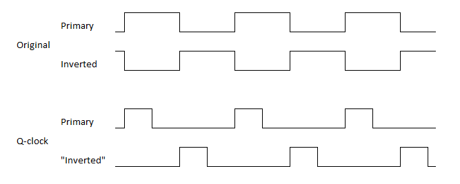
Part of the cycle when both clocks are low ensures that RAM's Write Enable is not active when control lines or bus changes.
While it is required only by RAM module, I see no downsides for using it globally (it might be an issue at high clock frequencies, though). Also, now other un-clocked parts (e.g. 193 counter for Stack Pointer) can be introduced without worries.
A great way to save bits in Control EEPROMs is to add demultiplexers, which activates just a single line from several. For example, by using 74*138 demultiplexer one can expand 3 bits to 7 control lines (technically - to 8, but you need to reserve one as "unused"). Currently there are 2 demultiplexers used - for OUT and for LOAD lines. For OUT it also prevents "invalid" conditions, such as multiple modules trying to output value on the bus.
While, in theory, there might be need to load same value into multiple modules simultaneously, I've not yet encountered one, and I'm happy to live with that limitation.
While trying to adjust the architecture for 16-bit memory space, I found out that having a single Main Bus and Memory Address Register comes with performance penalty, as all address transfers takes more cycles.
After some experimentation I found out that the most optimal solution is to remove the MAR entirely and have a separate 16-bit Address Bus, connected directly to the RAM chip(s).
Now, for example, Progam Counter can put an address on this bus, and the data is available to be sent on the Main Bus.
Additionally, I re-designed PC in a way, that it can output the "old" value on the Address Bus, and increment itself simultaneously. As a result, I can reduce the fetch stage of each instruction to just single cycle.
There are some situations (like JMP instruction), when data should be exchanged between Address and Main buses. There's a pair of special Transfer Registers, that allows to transfer low or high bytes between the buses.
It started with hooking up an Arduino (on its own at first, then expanded output with 595 shift registers, expanded even more with 139 demultiplexers and finally added 165 for expanded input) and writing some sketches to verify if modules work as expected. Soon I realized that the environment is a bit limited and while it can prove that everything works, it is not very helpful for diagnostics.
Reducing the functions of Arduino to "set control lines", "put to bus", "read from bus", "read flags", "pulse a clock", etc. and implementing higher level logic in Python, makes it more flexible and quicker to develop. Wrote a "client" that uses interactive input for diagnostics.
Started to implement Python functions that acts as an assembly instructions - for example: add(A, B) switches all control lines and issues clock ticks as needed for the addition operation. Basically - implemented microcode in Python. Later, with refactoring it became my main microcode definition and is used as primary source for microcode EEPROM contents.
Using the instruction-like functions and pytest framework wrote a quite thorough test suite. It can check couple hundred scenarios in just few seconds and point out if something does not work as expected. It has already saved me several times, when I did some rewiring.
At the moment the test module is swapped out for "real" EEPROM-based Control Logic, but I'll definitely find a way to use both of them in parallel, as it is too useful to be retired.
There was Python-based "assembler" at first, but in the end I adopted CustomAsm for machine code generation. There's an utility that takes my microcode definition and exports a file, describing them for CustomAsm. It takes it from there.
As the Test module allows great deal of flexibility, I was able to also develop a simple debugger. It can examine registers, RAM contents, single step. Addition of BRK instruction and corresponding control line introduced ability to set breakpoints and run the program in full-speed. Unfortunately it only works with emulator, as current hardware doesn't support both "normal" Control Logic and Test modules connected simultaneously.
Later I went even further and developed a simple IDE, that allows basic code editing, integrates with CustomAsm for compilation and has basic debugging functionality. One can single-step, set breakpoints, examine registers. The IDE is far from polished experience, still it is useful.
As side projects, there are 2 boards (Arduino Uno shields), firmware and client utility for programming DIP-28 and PLCC-32 EEPROMs (AT28C64 and AT28C256), as well as PLCC-32 Multi-Purpose Flash (SST39SF*).
EEPROM board has additional headers, giving access to address and data pins, allowing the board to act as a Test module, when connected to the Main Bus and control lines.
File upload and download uses XMODEM protocol, can be used with any terminal emulator. There's also a (*nix-only) command-line client utility for convenience.
In order to be able to work with the software side of the project, when hardware was not available, I wrote an in-Arduino emulator, that speaks same protocol as Test module. With time that proved to be insufficient, as Arduino was still needed, so I ported the C++ code to run on PC. It worked fine, but was a hand-crafted approximation of the CPU, so I could not really test all "what if" scenarios I'd like to.
So I decided to build another emulator, using proper hardware description language - Verilog. The idea was that I first make "building blocks" - (hopefully accurate) implementations of 74-series logic chips, and then connect them together into CPU modules. This way I get a runnable representation of the thing, how it should be built with real chips.
To provide connectivity with (virtualized) serial port, I built additional VPI module.
| Qty | Value | Footprint | References |
|---|---|---|---|
| 5 | LED | LED_SMD:LED_0805_2012Metric_Pad1.15x1.40mm_HandSolder | D1, D2, D3, D4, D5 |
| 4 | 100nF | Capacitor_SMD:C_0805_2012Metric_Pad1.15x1.40mm_HandSolder | C1, C3, C4, C7 |
| 4 | 10K | Resistor_SMD:R_0805_2012Metric_Pad1.15x1.40mm_HandSolder | R5, R6, R7, R8 |
| 4 | 330 | Resistor_SMD:R_0805_2012Metric_Pad1.15x1.40mm_HandSolder | R9, R10, R11, R12 |
| 3 | 1K | Resistor_SMD:R_0805_2012Metric_Pad1.15x1.40mm_HandSolder | R1, R2, R3 |
| 2 | 10nF | Capacitor_SMD:C_0805_2012Metric_Pad1.15x1.40mm_HandSolder | C2, C5 |
| 1 | 01x02_F | Connector_PinSocket_2.54mm:PinSocket_1x02_P2.54mm_Horizontal | J1 |
| 1 | 01x04_F | Connector_PinSocket_2.54mm:PinSocket_1x04_P2.54mm_Horizontal | J2 |
| 1 | 1M | clock-custom:POT_DIP_Dual_Vert | RV1 |
| 1 | 1M | Resistor_SMD:R_0805_2012Metric_Pad1.15x1.40mm_HandSolder | R4 |
| 1 | 1μF | Capacitor_SMD:C_0805_2012Metric_Pad1.15x1.40mm_HandSolder | C6 |
| 1 | 74HC00 | Package_SO:SOIC-14_3.9x8.7mm_P1.27mm | U4 |
| 1 | 74HC02 | Package_SO:SOIC-14_3.9x8.7mm_P1.27mm | U3 |
| 1 | SW_Push | Button_Switch_THT:SW_PUSH_6mm | SW1 |
| 1 | SW_SPDT | clock-custom:SW_Slide_1P2T_CK_OS102011MS2Q | SW2 |
| 1 | TLC556 | Package_SO:SOIC-14_3.9x8.7mm_P1.27mm | U1 |
32 parts, built around the 74HC00D, 74HC02 and TLC556CD. The full list of its parts is on this page, with links to each part's symbol and footprint where PCBKit's library has them.
From the Velko/8-bit-CPU repository on GitHub, at the commit this page was made from: the board is hardware/pcb/clock/clock.kicad_pcb. PCBKit opens the board in the browser, with nothing to install.
Its repository publishes it under the MIT licence: you may reuse it on that licence's terms (keep the author's notice, and for a copyleft licence share your changes alike).


astuder/neopixel-punk-console
Blinking RGB LEDs with 555s and a handful of 74-series logic

stockmann-lab/shim_amp_hardware_linear
Hardware related to open-source shim amplifier development for MRI research

CircuitMonkey/mos-kim1-replica
MOS KIM-1 6502 replica project using CHIPz modules.

slu4coder/Minimal-64x4-Home-Computer
My DIY TTL home computer with VGA and PS/2 and 4x the processing power of a Commodore C64 or Apple II.

slu4coder/Minimal-UART-Computer-1-2
Legacy: Version 1 and 2 of my TTL-only CPU featuring UART I/O, an expansion port, 512KB SSD at up to 10MHz clock speed


