

2 layers71 × 73 mm
Alarm
bbokser/persuasive_waker
An open source hardware alarm clock that can't be snoozed or turned off.
71 parts3MIT

 vekkuli/chess_clock
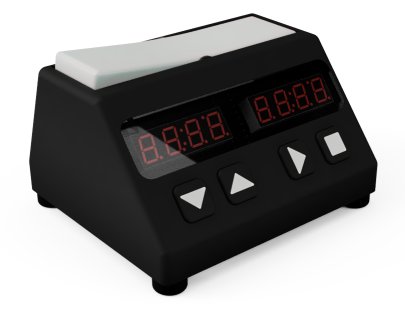
This repo contains design and fabrication files for my DIY chess clock project. The main components in the design are
Chess clock pcb is an open-source printed circuit board by vekkuli, from the vekkuli/chess_clock repository on GitHub, published under the MIT licence. It is a 2-layer board of 102 × 45 mm with 16 parts on 46 nets, routed with 328 tracks and 24 vias.
It is built around the B3F-4050 and TDCR1060M. Its parts include 6 switches, 2 ICs, 1 resistor and 1 connector. It belongs with the lEDs and displays boards and the AVR (ATmega, ATtiny) boards of this library.
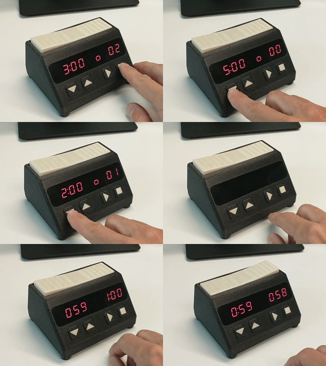
This repo contains design and fabrication files for my DIY chess clock project. The main components in the design are
Two 4-digit red 7-segment displays
MAX7219 display driver
Pro Micro microcontroller board
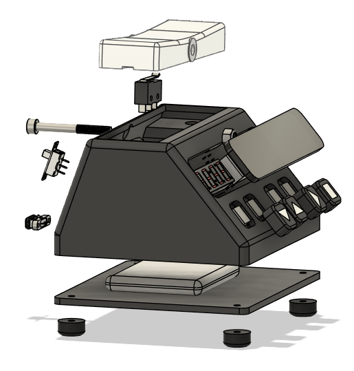
3D printed enclosure and other parts
5 V power supply (e.g. PowerBoost 500C and LiPoly battery)
Cut-to-shape acrylic window and tint filmThe KiCad project can be found in chess_clock_pcb folder. The fabrication files are also included and can be used to order the PCBs directly. The fabrication files were produced according to JLCPCB requirements. Black solder mask is recommended.
All the components are through-hole. Happy soldering! Just don't make the same mistake I did the first time and forget which side each component is supposed to be on :grin:. See the correct placement here:
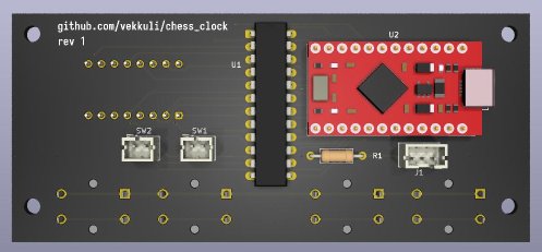
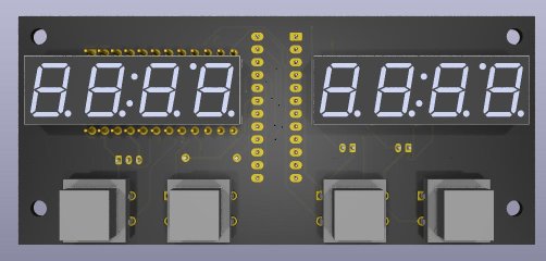
Note that the SW2 JST connector is not actually required. I put it there just in case but the current FW does not use it.
I used black PLA and white PETG. The main body was printed the display/button side facing down and using organic supports (PrusaSlicer). The following mesh files can be found in the 3d_print folder:
3d_print/bottom.3mf
3d_print/bushing.3mf
3d_print/button_type1.3mf
3d_print/button_type1_fill.3mf
3d_print/button_type2.3mf
3d_print/button_type2_fill.3mf
3d_print/main_body.3mf
3d_print/rocking_switch.3mf
Note that I actually used off-the-shelf plastic bushings that I just happened to have around, but I imagine 3D printed ones will work just as well.
The acrylic window cut shape can be found in 3d_print/acrylic_cut.dxf. 2 mm acrylic can be easily cut using for example a CO2 laser cutter.
The 5 % tint film (e.g. car window tint) is needed to get good contrast from the display.
Full (I hope) bill of materials below. Most parts can be sourced from DigiKey.
| Quantity | Item | Info/part number/digikey |
|---|---|---|
| 2 | 4-digit CC 7-segment display | TDCR1060M-ND |
| 1 | Display driver | MAX7219CNG-ND |
| 1 | USB-C port for 5 V input | 2057-USB-C20-S-VT-CS15-WP-BK-ND |
| 1 | 10k 1/4W resistor | Affects LED brightness |
| 1 | JST PH 2-pos connector | B2B-PH-K-S |
| 1 | JST PH 3-pos connector | B3B-PH-K-S |
| 1 | Arduino Pro Micro board | Microcontroller board |
| 4 | Tactile switches | SW414-ND |
| 1 | Omron limit switch | SS-5GL13 |
| 1 | PowerBoost 500C | 5V supply and LiPoly charger |
| 1 | LiPoly battery | e.g. 3.7 V/2500 mAh |
| 1 | M2.5 screws and nuts | |
| 1 | M3 screws and nuts | |
| 1 | M4x40 socket head screw | Cut to about 36 mm (or use M4x35) |
| 1 | M4 nyloc nut | |
| 1 | Acrylic window (2 mm) | Laser cut to shape |
| 1 | 5 % dark tint film | Greatly improves display contrast |
| 2 | (optional) O-ring | To soften the button press |
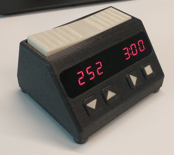
I don't know how they managed to mess this up :angry: but Pro Micro has a design flaw that causes it to brown out when started by applying power directly via either USB or VCC pin, i.e., not using the regulator on the board. One way to fix this, and what I did, is to remove the regulator IC. While at it, I decided to remove the tantalum capacitors as well.
| Qty | Value | Footprint | References |
|---|---|---|---|
| 4 | B3F-4050 | assets:SW_B3F-4050 | S1, S2, S3, S4 |
| 4 | MountingHole | MountingHole:MountingHole_3.2mm_M3 | H1, H2, H3, H4 |
| 2 | SW_SPST | Connector_JST:JST_PH_B2B-PH-K_1x02_P2.00mm_Vertical | SW1, SW2 |
| 2 | TDCR1060M | assets:DISPLAY_TDCR1060M | DS1, DS2 |
| 1 | 16k | Resistor_THT:R_Axial_DIN0207_L6.3mm_D2.5mm_P10.16mm_Horizontal | R1 |
| 1 | Conn_01x03 | Connector_JST:JST_PH_B3B-PH-K_1x03_P2.00mm_Vertical | J1 |
| 1 | MAX7221xNG | Package_DIP:DIP-24_W7.62mm_LongPads | U1 |
| 1 | Sparkfun_Pro_Micro | assets:Sparkfun_Pro_Micro | U2 |
It measures 102 × 45 mm and has 2 copper layers, 1.6 mm thick.
16 parts, built around the B3F-4050 and TDCR1060M. The full list of its parts is on this page, with links to each part's symbol and footprint where PCBKit's library has them.
From the vekkuli/chess_clock repository on GitHub, at the commit this page was made from: the board is chess_clock_pcb/chess_clock_pcb.kicad_pcb and its schematic chess_clock_pcb/chess_clock_pcb.kicad_sch. PCBKit opens the board in the browser, with nothing to install.
Its repository publishes it under the MIT licence: you may reuse it on that licence's terms (keep the author's notice, and for a copyleft licence share your changes alike).
bbokser/persuasive_waker
An open source hardware alarm clock that can't be snoozed or turned off.

Ilosariph/motorized-faders
RP2040 board (Pico-clone with RTL8720DN WiFi — GP4/GP5 not exposed) + TB6612FNG motor drivers + Alps motorized faders.

justinjchae/poko
Poko: a phone-free MagSafe companion. nRF52840 + Zephyr, round display, haptic ring, voice memos, iPhone app, parametric CAD, KiCad.


Rithvik-Vadlamani/kvm-switch
Four-layer HDMI/USB KVM design with STM32 firmware, supply supervision, and verification evidence


ZeusyBoy98/HexiLux
A custom open-source smart lighting solution, using tiling hexagonal panels. Featuring music sync and home assistant compatibility.