Skip to the content
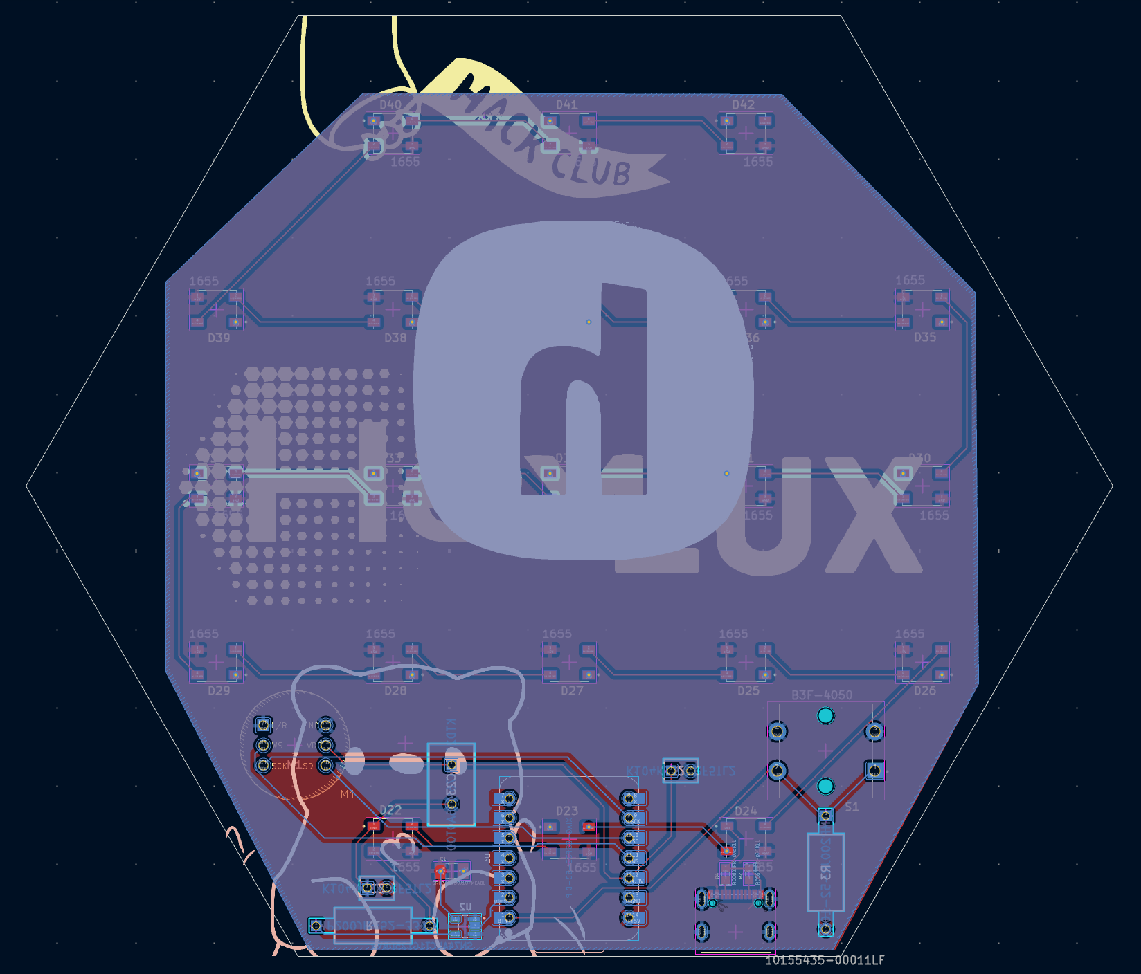
2 layers138.6 × 120 mmHexiLux v1, the printed circuit board in 3D

A custom open-source smart lighting solution, using tiling hexagonal panels. Featuring music sync and home assistant compatibility.

Size
138.6 × 120 mm
Copper layers
2
Thickness
1.6 mm
Parts
38
Nets
51
Pads
163
Tracks, vias
115, 23
Pours
2
Routed
Yes
KiCad
KiCad 9.0 (file 20241229)
Created
26 Feb 2026
Updated
25 Apr 2026

Overview

HexiLux v1 is an open-source printed circuit board by ZeusyBoy98, from the ZeusyBoy98/HexiLux repository on GitHub, published under the AGPL-3.0 licence. It is a 2-layer board of 138.6 × 120 mm with 38 parts on 51 nets, routed with 115 tracks and 23 vias.

It is built around the SN74AHCT1G125DBVR(UMW), K104K15X7RF5TL2 and 10155435-00011LF, with the B3F-4050, FMP200JR-52-10K and FMP200JR-52-330R among its other parts. Its parts include 21 diodes, 4 capacitors, 4 resistors, 2 ICs and 1 connector. It belongs with the ESP32 boards of this library.

Main components

7

README

README.md

HexiLux

Made for Hack Club Fallout.

Zine
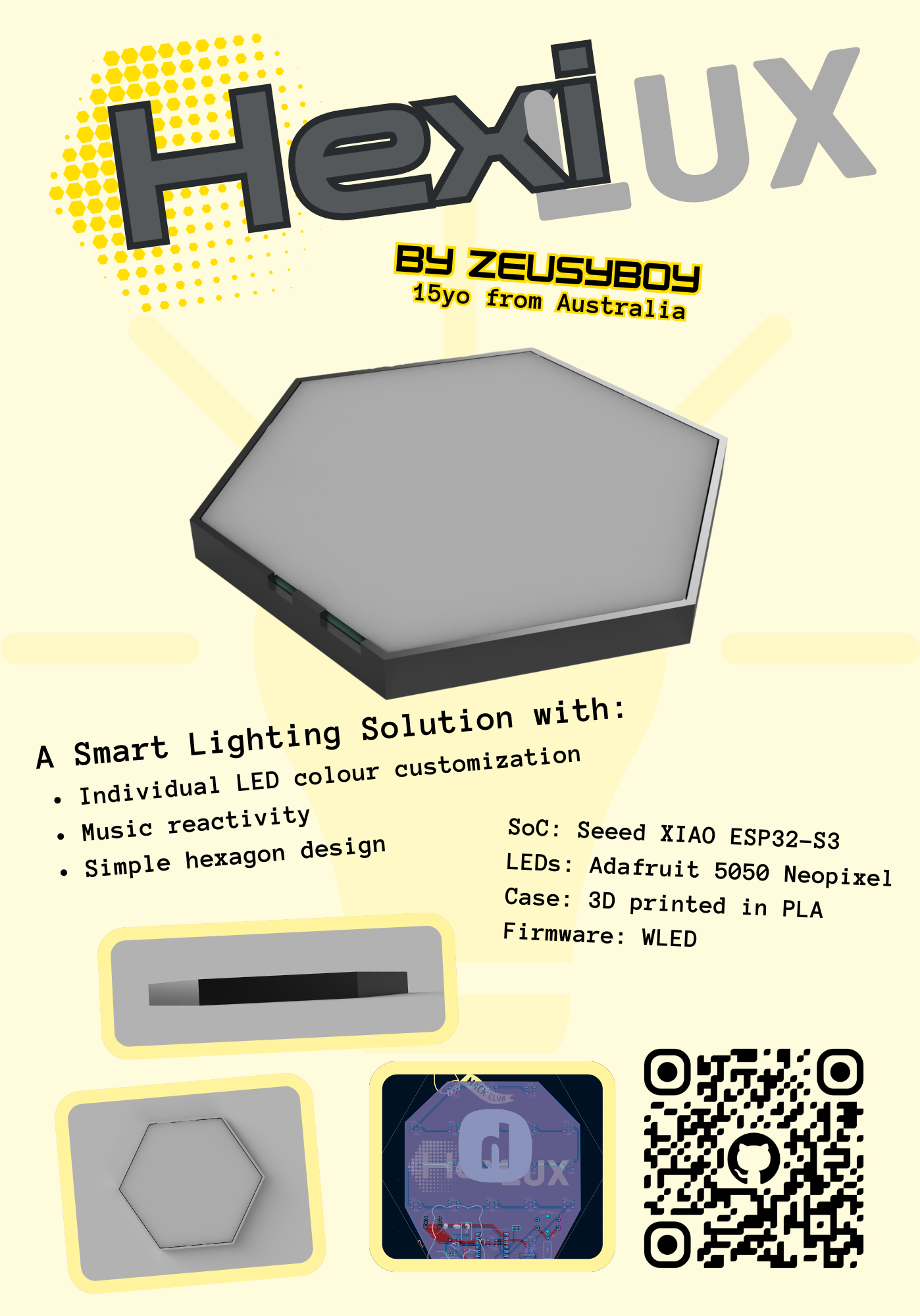
Zine

What does it do?

A custom open-source smart lighting solution, using tiling hexagonal panels. Featuring music sync and home assistant compatibility.

Why/Motivation?

Because I enjoy DJing and music reactive lights to go behind my setup would be really cool and elevate my experience.

How?

In order to make this project for yourself, you'll need to purchase/3D print the items in the bill of materials below.

QuantityItemURLUnit Price ($USD)Total Price ($USD)
1MicrophoneZaitronics5.575.57
3Neopixel (10 pack)DigiKey4.5013.50
1ButtonDigiKey0.520.52
1Board
DigiKey7.497.49
4100nF CapacitorDigiKey0.281.12
1330 ResistorDigiKey0.190.19
110k ResistorDigiKey0.190.19
25.1k ResistorDigiKey0.100.20
147uF CapacitorDigiKey0.860.86
1100uF CapacitorDigiKey0.440.44
1Level ShifterDigiKey0.140.14
1USBCDigiKey0.850.85
Case3D print files in /CAD(3D printing: 1.17)(3D printing: 1.17)
PCB29.24
Shipping3.70+20+9.52=33.22
Total93.53

Build Guide:

1. Preparation

Before starting, make sure you have:

  • All components from the BOM
  • A soldering iron + solder
  • Tweezers (there are lots of small components)
  • Flux (helpful)
  • A 3D printer (or get the printed parts from someone else)
  • A USB-C cable
  • A USB-C power adapter
2. Soldering

Take your pcb and begin soldering components to it
Wiring schematic: schematic Recommended order:
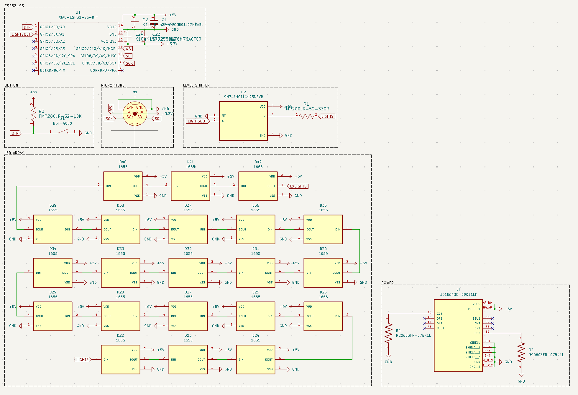
  • SMD Components (resistors/capacitors, neopixels, logic converters)
  • Microcontroller (Seeed XIAO ESP32-S3)
  • Through-hole components (resistors/capacitors, buttons, microphone)
3. Case
  • 3D print the case bottom and top.
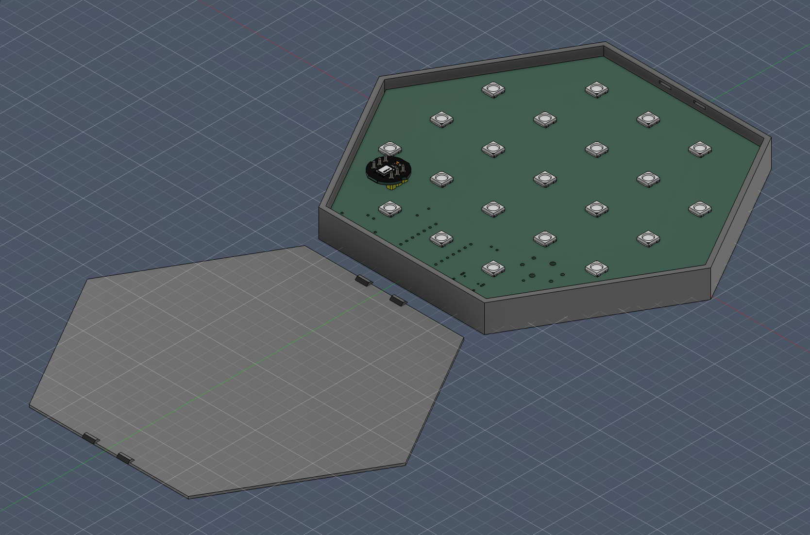
  • Place the PCB into the case bottom
  • Snap on the case top
4. Firmware
  • Plug the middle USB-C port (ESP32-S3) into a computer
  • Go to https://install.wled.me/
  • Install the WLED firmware to the board
  • Unplug
  • Plug a power adapter into the off-centre USB-C port
  • Follow the instructions here to start using: https://kno.wled.ge/basics/getting-started/

Enjoy your HexiLux panel!

Renders

image image image

Designing

image image

Parts

38
QtyValueFootprintReferences
211655LED_1655_5050_neopixel:LED_1655_5050_neopixelD22, D23, D24, D25, D26, D27, D28, D29, D30, D31, D32, D33, D34, D35, D36, D37 +5
2K104K15X7RF5TL2K104K15X7RF5TL2_VIS_100nF_50V:K104K15X7RF5TL2_VISC2, C24
2RC0603FR-075K1L5.1k_0603_DK:5.1k_0603_DKR2, R4
110155435-00011LFUSBC-DigiKey-PD:AMPHENOL_10155435-00011LFJ1
1B3F-4050SW_B3F-4050:SW_B3F-4050S1
1FMP200JR-52-10KFMP200JR_52_10K:YAG_FMP200_YAGR3
1FMP200JR-52-330RYAG_FMP200_YAG_52_330k:YAG_FMP200_YAG_52_330kR1
1GRM31CD80J107MEA8L100uf_5V_1206:100uf_5V_1206C1
1KTD250B476M76A0T00CAP_NTD_76_05_5T_NIP_47uF_25V:CAP_NTD_76_05.5T_NIPC23
1LOGOSilkscreen:soupG***
1LOGOSilkscreen:hackclub-logoG***
1LOGOSilkscreen:hackclub-squareG***
1LOGOSilkscreen:HexiLux-LogoG***
1SN74AHCT1G125DBVR74AHCT_level_shifter:74AHCT_level_shifterU2
1XIAO-ESP32-S3-DIPXIAO_Series_Footprints:XIAO-ESP32-S3-DIPU1
1~INMP441_Omnidirectional_Microphone:INMP441M1

Similar boards

  • 4 layers273 × 178 mmPico thing, the printed circuit board in 3D

    Pico thing

    markrvmurray/pico-thing

    An 8-bit MC6809E / HD6309E single-board computer with a pair of Raspberry Pi Pico 2 (RP2350 / Pimoroni PGA2350) modules acting as intelligent bus peripherals, a 1–2 MB banked-RAM DAT/MMU, a 40-pin PATA hard-disk…

    206 parts1BSD-2-Clause
  • 2 layers80 × 70 mmJli2555-tin can, the printed circuit board in 3D

    Jli2555-tin can

    anauseam/JLI-2555-tin-can-mic

    JLI-2555 Microphone preamplifier

    26 partsCERN-OHL-P-2.0
  • 2 layers160 × 60 mmCarrier, the printed circuit board in 3D

    Carrier

    ntotten/Kohler-DTV-Plus

    Replacement interface and CGI protocol analysis for the Kohler DTV+ shower system controller (K-99695-NA / K-99693-P-NA), plus an open investigation into mid-shower shutoffs.

    52 parts
  • 2 layers68.6 × 53.3 mmMie1001 daq simple, the printed circuit board in 3D

    Mie1001 daq simple

    Chaospossum/mie1001-daq

    MIE1001 Team 5: DAQ firmware and Arduino shield designs (preamp, ADS1115, MCP4725)

    35 parts
  • 2 layers155 × 93 mmMotorized faders, the printed circuit board in 3D

    Motorized faders

    Ilosariph/motorized-faders

    RP2040 board (Pico-clone with RTL8720DN WiFi — GP4/GP5 not exposed) + TB6612FNG motor drivers + Alps motorized faders.

    66 parts
  • 4 layers55 × 85 mmPokodoro, the printed circuit board in 3D

    Pokodoro

    justinjchae/poko

    Poko: a phone-free MagSafe companion. nRF52840 + Zephyr, round display, haptic ring, voice memos, iPhone app, parametric CAD, KiCad.

    52 parts
  • 4 layers100 × 100 mmKvm switch, the printed circuit board in 3D

    Kvm switch

    Rithvik-Vadlamani/kvm-switch

    Four-layer HDMI/USB KVM design with STM32 firmware, supply supervision, and verification evidence

    170 parts
  • 2 layers102 × 45 mmChess clock pcb, the printed circuit board in 3D

    Chess clock pcb

    vekkuli/chess_clock

    This repo contains design and fabrication files for my DIY chess clock project. The main components in the design are

    16 partsMIT

Questions

How big is the HexiLux v1 PCB?

It measures 138.6 × 120 mm and has 2 copper layers, 1.6 mm thick.

What parts does the HexiLux v1 use?

38 parts, built around the SN74AHCT1G125DBVR(UMW), K104K15X7RF5TL2, 10155435-00011LF and B3F-4050. The full list of its parts is on this page, with links to each part's symbol and footprint where PCBKit's library has them.

Where can I download the HexiLux v1 KiCad files?

From the ZeusyBoy98/HexiLux repository on GitHub, at the commit this page was made from: the board is PCB/HexiLux-v1.kicad_pcb and its schematic PCB/HexiLux-v1.kicad_sch. PCBKit opens the board in the browser, with nothing to install.

Can I use the HexiLux v1 design in my own project?

Its repository publishes it under the AGPL-3.0 licence: you may reuse it on that licence's terms (keep the author's notice, and for a copyleft licence share your changes alike).