
2 layers121 × 73 mm

An open source hardware alarm clock that can't be snoozed or turned off.
Alarm is an open-source printed circuit board by bbokser, from the bbokser/persuasive_waker repository on GitHub, published under the MIT licence. It is a 2-layer board of 71 × 73 mm with 71 parts on 120 nets, routed with 489 tracks and 69 vias.
It is built around the AS1115-BSST, SHT40-BD1B-R2 and MAX31328NELB+, with the PEC11S-929K-S0015, TDCR1060M and TL3301BF260QJ among its other parts. Its parts include 18 capacitors, 16 resistors, 8 switches, 6 ICs and 5 diodes. It belongs with the lEDs and displays boards and the RP2040 boards of this library.


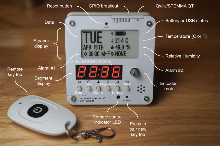
Persuasive Waker is an open source hardware alarm clock that can't be snoozed or turned off. The alarm is deactivated via a remote key fob, which should be placed as far from the user's bed as possible. E.g. in the bathroom.
The KiCad design files are located in the hw folder.
The STEP assembly is located here.
If you just want STLs for printing, they're here.
| Item | QTY | Source |
|---|---|---|
| Case | 1 | 3D Print |
| Screen Holder | 1 | 3D Print |
| Spacer | 2 | 3D Print |
| M2.5x0.45-12-SHCS-SS304 | 4 | |
| M2.5x0.45-6-SHCS-SS304 | 4 | |
| M2.5x0.45-4-FHS-SS304 | 2 | |
| PRESSNUT-M2.5x0.45-SS304 | 2 | Mouser |
| Battery Holder | 1 | Mouser |
| THRIN-M2.5X0.45-HS-PL-4L3.5D-BR | 8 | Amazon |
| E-Paper Display | 1 | AliExpress |
| Key Fob | 1 | AliExpress |
| Alarm PCB | 1 | Custom PCBA Order |
| Front Plate | 1 | Custom PCB Order |
| Rear Plate | 1 | Custom PCB Order |
Install CircuitPython on your Pico by following this guide. The last version tested with this device is 9.2.6.
Install circup on your computer.
Run the following commands to install all necessary libraries.
circup bundle-add adafruit/circuitpython-fonts
circup install adafruit_sht4x adafruit_ssd1680 adafruit_display_text adafruit_ds3231 adafruit_datetime adafruit_display_shapes font_ostrich_sans_black_24 font_ostrich_sans_black_60
Delete code.py from the Pico's storage.
Clone this repo onto your computer and copy+paste everything in the src folder to the Pico's storage.
The alarm clock should be functioning now.
See here.
Replace the old src files with the new ones on the v3.1 branch.
Install circup and run the following.
circup bundle-add adafruit/circuitpython-fonts
circup uninstall font_ostrich_sans_black_30 font_ostrich_sans_black_72
circup install font_ostrich_sans_black_24 font_ostrich_sans_black_60
circup update
Alternatively, you can download the requirements.txt and run the following:
circup install -r /path/to/requirements.txt| Qty | Value | Footprint | References |
|---|---|---|---|
| 14 | 1uF | Capacitor_SMD:C_0603_1608Metric | C2, C4, C5, C7, C8, C9, C10, C11, C12, C13, C14, C15, C16, C17 |
| 9 | 10kΩ | Resistor_SMD:R_0603_1608Metric_Pad0.98x0.95mm_HandSolder | R1, R3, R4, R5, R7, R8, R9, R10, R11 |
| 6 | TL3301BF260QJ | SamacSys_Parts:TL3301BF260QJ | S3, S4, S5, S6, S7, S8 |
| 4 | 4.7uF | Capacitor_SMD:C_0603_1608Metric | C1, C3, C6, C18 |
| 4 | MBR0530 | Diode_SMD:D_SOD-123 | D1, D2, D3, D4 |
| 4 | MountingHole_Pad | MountingHole:MountingHole_2.7mm_M2.5_DIN965_Pad | H1, H2, H3, H4 |
| 3 | TestPoint | TestPoint:TestPoint_Pad_1.5x1.5mm | TP1, TP2, TP3 |
| 2 | 130Ω | Resistor_SMD:R_0603_1608Metric_Pad0.98x0.95mm_HandSolder | R15, R16 |
| 2 | DMG2305UX-7 | SamacSys_Parts:SOT96P240X115-3N | Q2, Q3 |
| 2 | RKB2SJK250SMTR_LFS | SamacSys_Parts:RKB2SJK250SMTRLFS | S1, S2 |
| 1 | 0.47Ω | Resistor_SMD:R_0603_1608Metric_Pad0.98x0.95mm_HandSolder | R2 |
| 1 | 14kΩ | Resistor_SMD:R_0603_1608Metric_Pad0.98x0.95mm_HandSolder | R12 |
| 1 | 180Ω | Resistor_SMD:R_0603_1608Metric_Pad0.98x0.95mm_HandSolder | R6 |
| 1 | 1kΩ | Resistor_SMD:R_0603_1608Metric_Pad0.98x0.95mm_HandSolder | R13 |
| 1 | 2SC5585TL | SamacSys_Parts:2SC5585TL | Q4 |
| 1 | 47Ω | Resistor_SMD:R_0603_1608Metric_Pad0.98x0.95mm_HandSolder | R14 |
| 1 | 68 uH | SamacSys_Parts:INDM3225X240N | L1 |
| 1 | 975 | SamacSys_Parts:975 | J2 |
| 1 | AS1115-BSST | Package_SO:QSOP-24_3.9x8.7mm_P0.635mm | U2 |
| 1 | CSS-I4B20-SMT-TR | SamacSys_Parts:CSSI4B20SMTTR | LS1 |
| 1 | FFC2B35-24-T | SamacSys_Parts:FFC2B3524T | J1 |
| 1 | M20-7920642R | SamacSys_Parts:M207920642R | J3 |
| 1 | MAX31328NELB+ | SamacSys_Parts:MAX31328NELB | IC2 |
| 1 | PEC11S-929K-S0015 | SamacSys_Parts:PEC11S929KS0015 | IC3 |
| 1 | RaspberryPi_Pico | Module_RaspberryPi_Pico:RaspberryPi_Pico_Original_SMD | U1 |
| 1 | SHT40-BD1B-R2 | SamacSys_Parts:SHT40BD1BR2 | IC1 |
| 1 | SM04B-SRSS-TB_LF__SN__P_ | SamacSys_Parts:SM04BSRSSTBLFSNP | J4 |
| 1 | Si1308EDL-T1-GE3 | SamacSys_Parts:SOT65P210X110-3N | Q1 |
| 1 | TDCR1060M | footprints:TDCG1060M_VIS | U3 |
| 1 | WP424IDT | SamacSys_Parts:WP424IDT | LED1 |
| 1 | ~ | RX480E:RX480E | A1 |
It measures 71 × 73 mm and has 2 copper layers, 1.6 mm thick.
71 parts, built around the AS1115-BSST, SHT40-BD1B-R2, MAX31328NELB+ and PEC11S-929K-S0015. The full list of its parts is on this page, with links to each part's symbol and footprint where PCBKit's library has them.
From the bbokser/persuasive_waker repository on GitHub, at the commit this page was made from: the board is hw/alarm/alarm.kicad_pcb and its schematic hw/alarm/alarm.kicad_sch. PCBKit opens the board in the browser, with nothing to install.
Its repository publishes it under the MIT licence: you may reuse it on that licence's terms (keep the author's notice, and for a copyleft licence share your changes alike).


hkienle/osh-vacuum
This PCB is designed to control a high RPM impeller for vacuum machines. It provides comprehensive control and monitoring capabilities with modern connectivity options.


binaryBeachLLC/tradewind
Tradewind TW-1: solar LoRaWAN field sensor. KiCad 9 board, CadQuery enclosure, RUI3 firmware, simulations, test data, report and datasheet.

schrodlm/nxp_hal
In this assignment the target platform changes from the STM32F407 to the NXP S32K118, an Arm Cortex‑M0+ microcontroller from the S32K1xx automotive family.

