
2 layers60 × 30 mm
Controller
google/mozc-devices
Circuit diagrams and firmware source code for Gboard DIY keyboards
11 parts3kApache-2.0
3D-printed CNC mill using stepper motors with PyGame based user interface. Supports 3D lines, arcs, and cubic Bezier curves with velocity and acceleration limits.
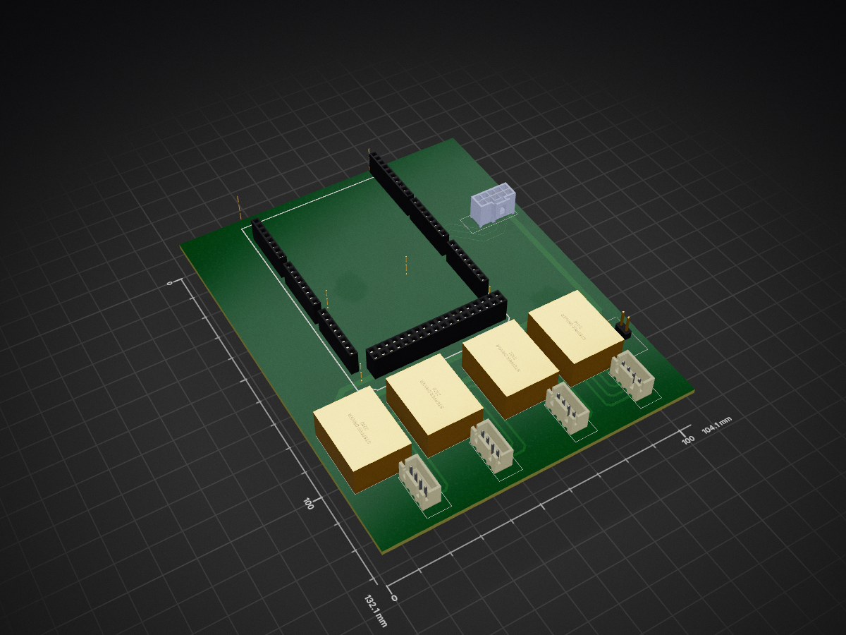
CNC PCB is an open-source printed circuit board by VedantGithub123, from the VedantGithub123/DIY-CNC-Mill repository on GitHub. It is a 2-layer board of 104.1 × 132.1 mm with 11 parts on 122 nets, routed with 192 tracks and 0 vias.
Its parts include 5 ICs and 5 connectors. It belongs with the robots and motor control boards and the AVR (ATmega, ATtiny) boards of this library.
The goal of this project is to develop a G-code interpreter and CNC mill. The CNC mill can follow straight lines, arcs and cubic bezier curves. It is 3D-printed with PETG, uses stepper motors, which are controlled with an Arduino Mega. The code ran on the laptop sends motor speeds to the Arduino, which moves the motors accordingly. To use the program, connect the Arudino Mega to your laptop with a USB cable. Run the Python file
SolidWorks is used for the CAD
KiCAD is used for the circuit diagram and PCB
Ensure Git is installed and setup to work with he repository
Clone the project repository to your local machine and navigate into the directory:
git clone https://github.com/VedantGithub123/DIY-CNC-Mill
cd DIY-CNC-Mill
Python and the PyGame library are needed
Arduino and the AccelStepper library are needed
The main branch is the organized working branch. Below is an overview of the folder structure for the main branch of this repository
DIY-CNC-Mill/
├── build/
├── electrical/
├── input/
├── media/
├── src/
│   ├── arduino/
│   ├── assets/
│   └── run.py
└── README.mdbuild/: Contains files relating to the physical construction of the device
design/: Contains the CAD files of the design
electrical/: Contains files relating to the electrical wiring of the device
input/: Location of G-code files to run
media/: Contains photos of the mill
src/: Contains all source code and assets
arduino/: Code to run on the Arduino
assets/: Photos needed for the GUI
run.c: Program to run on the laptop
README.md: Project repository documentation
Before deciding on how the program specifications were, I needed to determine how I wanted to organize the code. I wanted to keep the UI, G-code interpreter, and serial communication sections separate. A constant loop was needed for the UI, then when buttons are pressed, it would tell the CNC how to move or change the data, such as what file is being read. Finally, during the loop, the interpreter should calculate what speeds are needed and use the serial communication to send it to the Arduino.
I decided to follow this marlin G-code protocol (mostly): https://marlinfw.org/meta/gcode/
However, the only commands that can be used are:
The path-following algorithms in run.py use the same control approach for straight lines, arcs, and cubic Bezier curves. Each path can provide a position and tangent for a given parameter, allowing the main update loop to follow different G-code commands without duplicating the motion-control logic.
During each update, the program determines the point on the active path that is closest to the current spindle position. It calculates the tangent at that point and combines it with a correction vector from the spindle to the path. The correction keeps the tool close to the programmed path, while the tangent continues the motion toward the end of the command. This produces the velocity vector that run.py sends to the Arduino through the serial connection.
The requested velocity is then constrained by the machine's acceleration and deceleration limits. At the beginning of a movement, the speed increases gradually. As the spindle approaches the endpoint, the speed is reduced so the target can be reached without overshooting. If the next movement is compatible with the current direction, the code can transition directly into it instead of stopping between commands; commands such as stops and dwells require the velocity to reach zero.
The update loop repeats these calculations while the machine is running. When the spindle is sufficiently close to the endpoint and its remaining velocity is small enough, run.py completes the current command and advances to the next one. This separates path geometry, speed limiting, and serial output while allowing the same motion loop to control lines, arcs, and Bezier curves.
When the computer tries to connect with the Arduino, the Arduino will say CNC Ready. The computer will need to read this before continuing. The Python program opens the Arduino's serial connection, waits for this ready message, and then begins sending movement and spindle commands generated by the G-code interpreter.
The Arduino program reads the commands received over the serial connection, converts them into motor and spindle actions, and uses the stepper-motor controllers to execute them. It continues processing incoming commands while the machine is running and reports status messages back to the computer when necessary. The Python program reads these responses so that it can keep the user interface and machine state synchronized.
If the ready message is not received, the Python program should not send movement commands. The Arduino must be connected over USB and powered before starting the Python program.
| Qty | Value | Footprint | References |
|---|---|---|---|
| 1 | 12V Power Source | Library:2 Pin Connector | J5 |
| 1 | ARDUINO_MEGA_SHIELD | Library:ARDUINO MEGA SHIELD | SHIELD1 |
| 1 | Motor Driver | Library:L298 | U5 |
| 1 | Stepper 1 | Library:4 Pin Connector | J1 |
| 1 | Stepper 2 | Library:4 Pin Connector | J2 |
| 1 | Stepper 3 | Library:4 Pin Connector | J3 |
| 1 | Stepper 4 | Library:4 Pin Connector | J4 |
| 1 | Stepper Driver 1 | Library:TMC2209 | U1 |
| 1 | Stepper Driver 2 | Library:TMC2209 | U2 |
| 1 | Stepper Driver 3 | Library:TMC2209 | U3 |
| 1 | Stepper Driver 4 | Library:TMC2209 | U4 |
It measures 104.1 × 132.1 mm and has 2 copper layers, 1.6 mm thick.
11 parts. The full list of its parts is on this page, with links to each part's symbol and footprint where PCBKit's library has them.
From the VedantGithub123/DIY-CNC-Mill repository on GitHub, at the commit this page was made from: the board is electrical/CNC PCB/CNC PCB.kicad_pcb and its schematic electrical/CNC PCB/CNC PCB.kicad_sch. PCBKit opens the board in the browser, with nothing to install.
Its repository states no licence, so its author keeps all rights: ask VedantGithub123 before reusing the design.
google/mozc-devices
Circuit diagrams and firmware source code for Gboard DIY keyboards


FrameworkComputer/ExpansionCards
Reference designs and documentation to create Expansion Cards for the Framework Laptop

hoglet67/RGBtoHDMI
Bare-metal Raspberry Pi project that provides pixel-perfect sampling of Retro Computer RGB/YUV video and conversion to HDMI

hackclub/OnBoard
💡 Join 1,000 teenagers and make your first PCB with a $100 grant!


tardate/LittleArduinoProjects
a collection of "Little Electronic & Arduino Projects", most involving electronics or an Arduino in one way or another!

basilfx/TRADFRI-Hacking
Hacking IKEA TRÅDFRI products, such as light bulbs, window blinds and other accessories.