KNX–DALI Gateway
Open-source DIN-rail gateway between a wired KNX TP line and one DALI / DALI-2 line: up to 64 control gear plus DALI-2 multi-master input devices, commissioned entirely through ETS. An optional integrated, isolated DALI bus supply runs from 20–32 V auxiliary DC (a 24 V PSU or the KNX white/yellow pair); the same input also powers the gateway core, with the KNX bus as a seamless fallback. The WiFi dashboard and MQTT are extras: lighting control and ETS provisioning never depend on them.
[!NOTE]
Pre-hardware prototype. Verified by native unit tests, a Docker KNX/DALI integration lab, KiCad DRC and isolation checks, JLCPCB footprint and pinout checks, and exact-solid CadQuery fit tests. No board has been powered on yet, and no KNX or DALI certification is claimed.
Downloads ·
Screenshots ·
Hardware ·
Building one ·
How it works ·
Development
Downloads
| What | Where | Use |
|---|
| First install (USB) | firmware-full-usb.bin | Bootloader, partition table and firmware in one image for an empty ESP32-C6. Connect the XIAO over USB-C and write it at 0x0: esptool.py --chip esp32c6 write_flash 0x0 firmware-full-usb.bin. Clears all settings. |
| Update | firmware.bin | Drop it onto the Firmware tab of the web interface. Updates firmware and web UI together; settings are kept. |
| ETS product database | KnxDaliGateway.knxprod | Import into ETS 5.7 / 6: 64 lamp channels (DT6/DT7/DT8), 16 groups, broadcast, 8 DALI-2 input devices with up to 4 instances each (1,321 group objects). |
| Hardware bundles | knx-dali-gateway-hardware-v2.zip / v3.zip | Gerbers, JLCPCB BOM/CPL, STEP assemblies, printable STL/3MF case, assembly_parts.csv. |
Screenshots
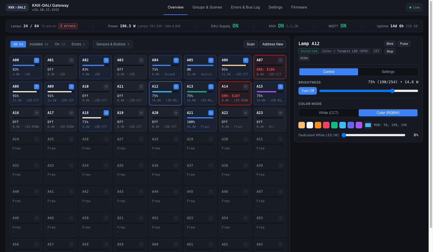
The web interface is built into the firmware and served by the ESP32-C6 itself (live WebSocket updates, no cloud):
More of the web interface: lamp settings, groups and scenes, error log, bus monitor, settings
| Lamp settings | Groups & scenes |
|---|
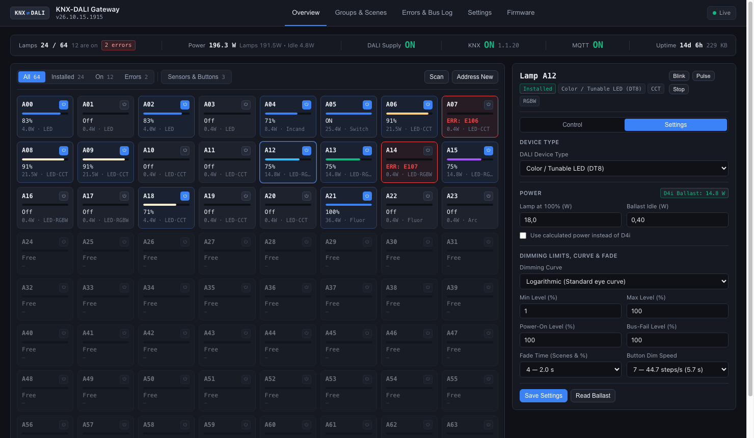 | 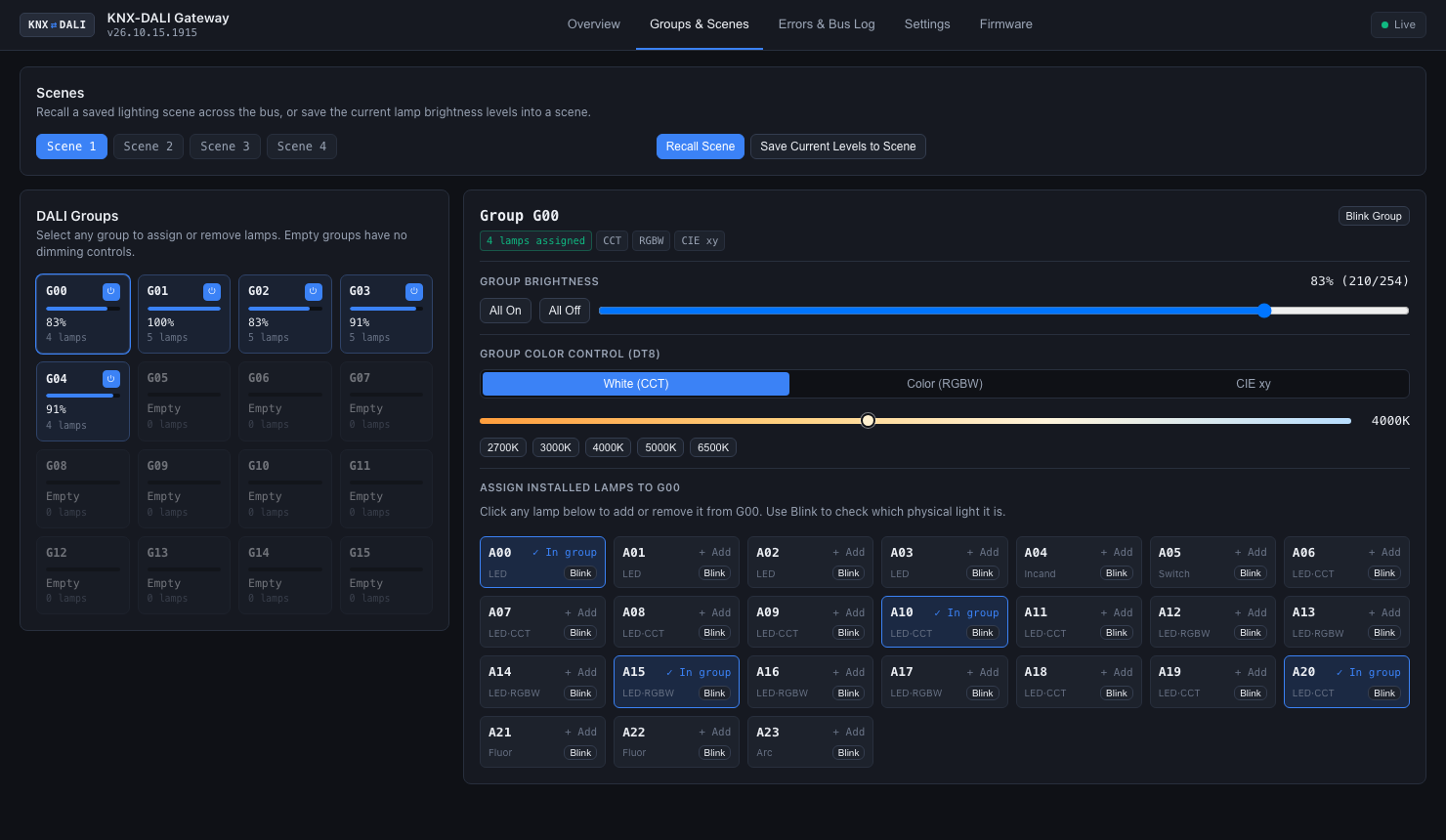 |
| Device type, dimming curve, limits, fade, D4i or calculated power, ballast replacement | 16 scenes, 16 groups (G00–G15), group colour, membership written to the ballast |
| Error log | Live DALI bus monitor |
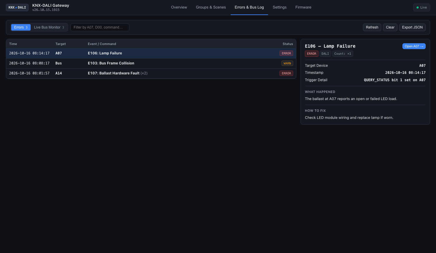 | 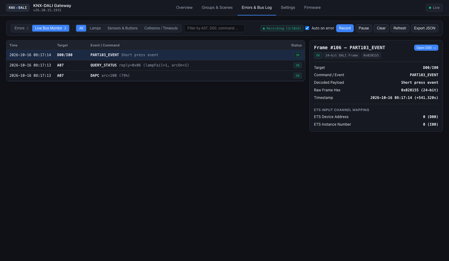 |
| Persistent NVS history with remedies | 8/16/24-bit frames and collisions: 1,024 rows on the device, 10,000 in the browser |
| Settings | |
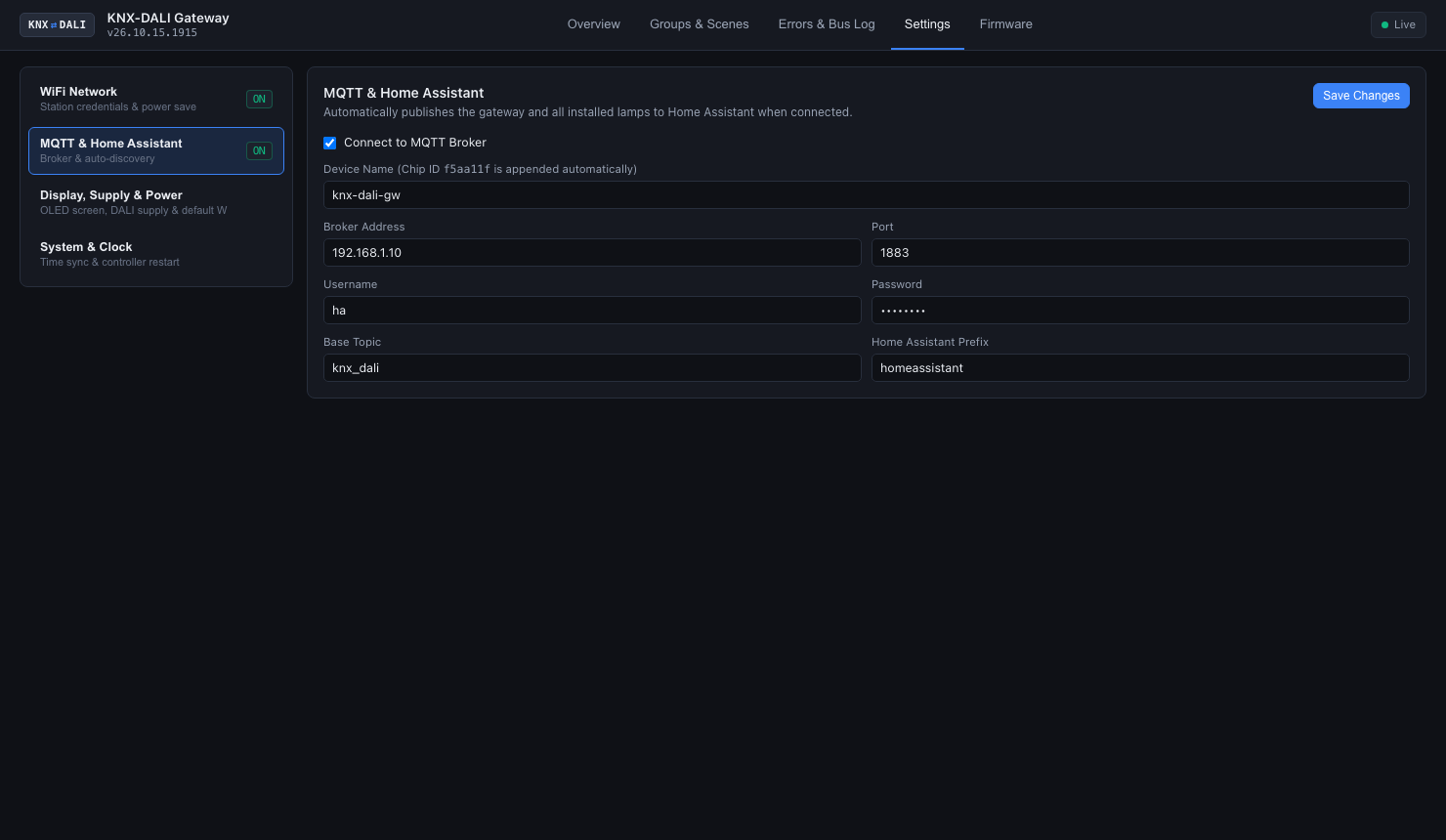 | |
| WiFi, MQTT with Home Assistant auto-discovery, power model | |
- Overview: live level, DT8 colour (Tc, RGBW, xy), per-lamp power (native D4i Part 252 or calculated), lamp finder, fault codes; a second grid for DALI-2 buttons and sensors (IEC 62386-103 / 301–304).
- Home Assistant: one gateway device (total power and energy) plus every populated lamp with on/off, dimming, colour, power and fault entities.
Front-panel OLED pages: V3 portrait 64×128, V2 landscape 128×64
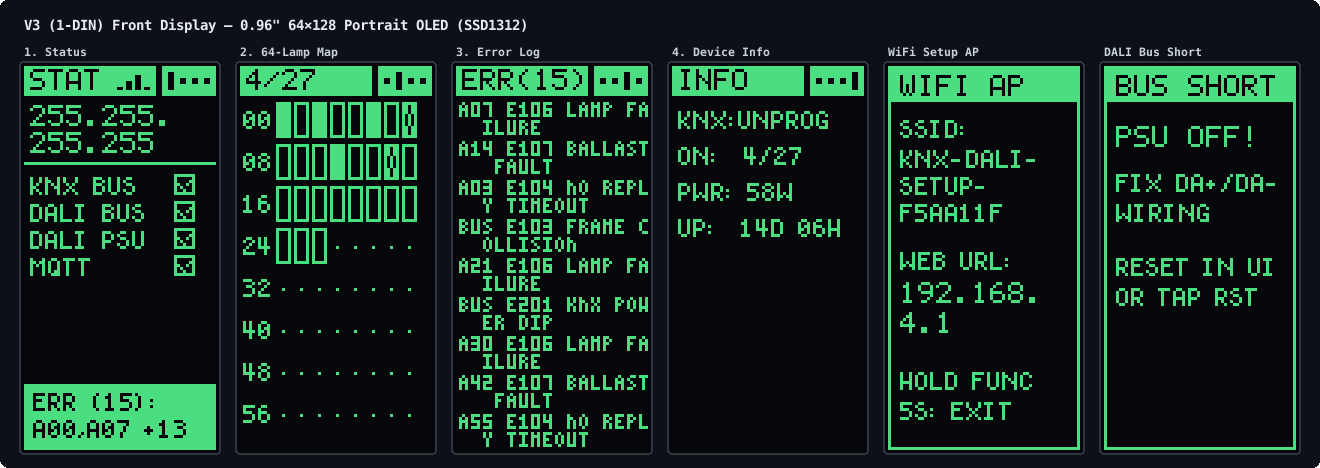
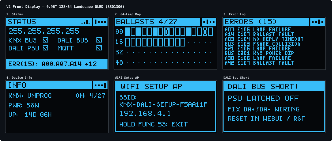
FUNC steps through the pages; holding it for 5 s starts the WiFi setup portal.
Hardware
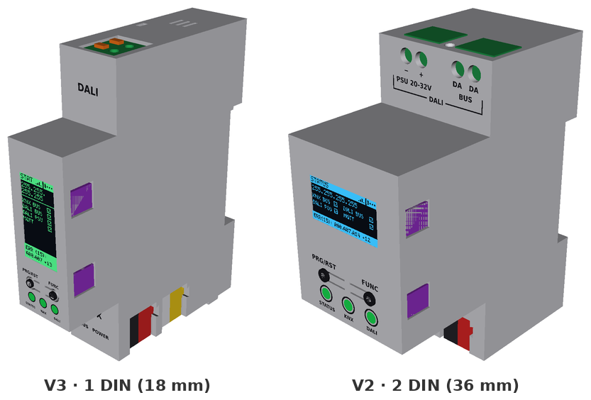
Two variants share the circuit blocks (hardware/circuits/blocks/), the XIAO ESP32-C6 pinout (gateway/src/firmware/Board.hpp) and the firmware:
| V3 (v3) | V2 (v2) |
|---|
| Width | 1 DIN (18 mm) | 2 DIN (36 mm) |
| Boards | 2: two-sided vertical main, front ui | 3: main, interface, ui |
| AUX core converter | TRACO TMR 2411 (2 W), on a tongue of main in the front protrusion | TRACO TRN 3-2411 (3 W), on the back of main |
| DALI terminal | Kefa KF142R push-in | MX126 screw |
| KNX / AUX | PST 1,0 pin strips (red/black, yellow/white plugs) | PST 1,0 KNX, MX126 screw AUX |
| Display | 0.96" 64×128 portrait SSD1312, solder flex tail | 0.96" 128×64 SSD1306 module, 4-pin header |
| Buttons | Omron B3U pressed through C-shaped spring tabs in the cover | same |
| Main ↔ UI link | 8-pin 0.5 mm FFC (Type B, 50 mm) | 10-pin JST-SH cable |
| Case | Side-opening clamshell, snap-fit | Two 2.5×10 screws, UI snaps |
| Release | hardware/releases/v3/ | hardware/releases/v2/ |
V3 renders: assembly and boards
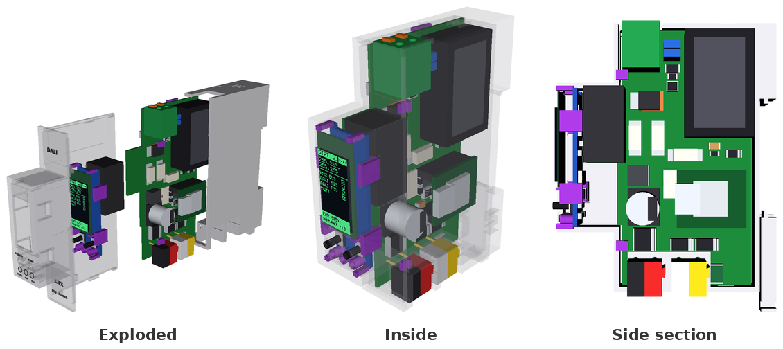
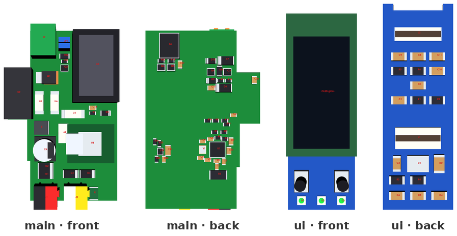
PCB artwork: main top · bottom · ui top · bottom.
Fit drawings: front · side.
V2 renders: assembly and boards
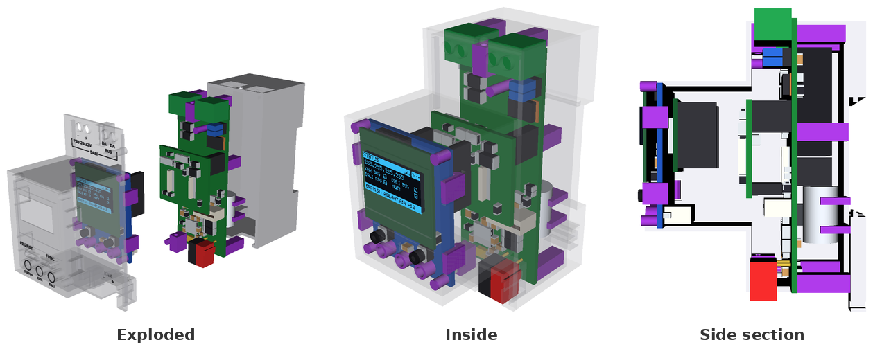
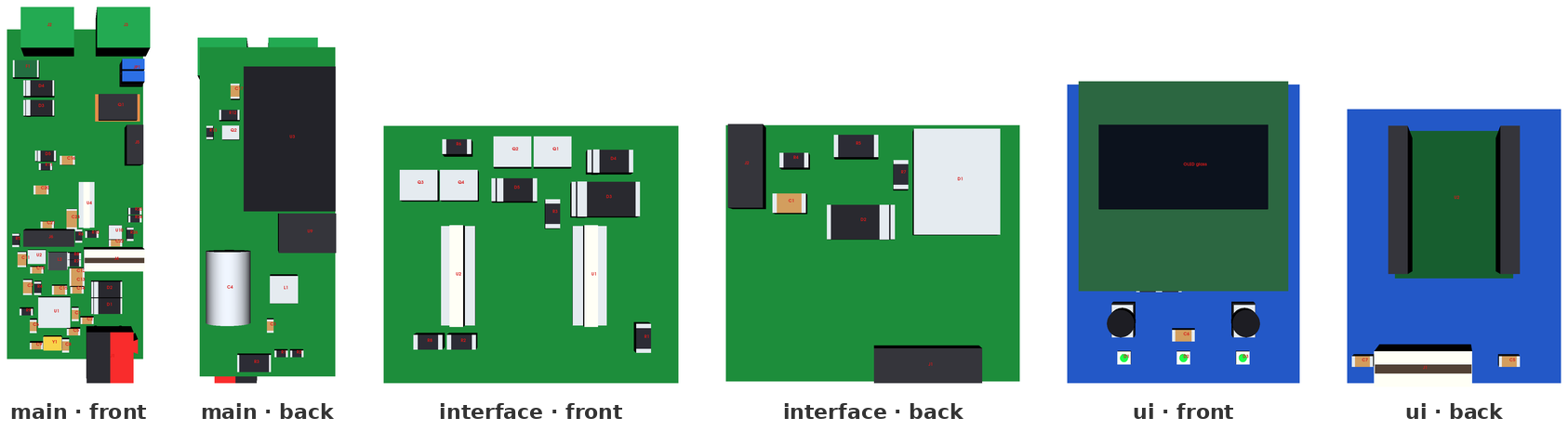
PCB artwork: main top · bottom · interface top · bottom · ui top · bottom.
Fit drawings: front · side.
Pin table, LED chain and button ladder: hardware/docs/variants.md. Pre-manufacturing reviews: review-2026-10-23.md, review-2026-10-22.md; rework for boards made from 59eea1f: rework-rev-c.md.
Building one
Each hardware/releases/<variant>/ folder is a complete manufacturing package.
- PCBs with SMT assembly (JLCPCB). Upload
panel/panel_gerbers.zip (V3: 66.0 × 78.1 mm, 4 layers, 1.2 mm; V2: 98.5 × 76.6 mm, 4 layers, 1.6 mm) with assembly on both sides, panel/panel_bom_jlc.csv and panel/panel_cpl_jlc.csv. You order one PCB and one PCBA job and snap the boards apart. Per-board files are in main/, ui/ (and interface/ on V2). Compare renders/top.svg / bottom.svg with JLCPCB's placement preview.
Building it yourself: order_lcsc.csv (LCSC BOM tool: map LCSC Part Number and Quantity) and order_elsewhere.csv (electronics LCSC does not sell, with Mouser / Digi-Key / TME numbers) cover every electronic part of one gateway; screws, foam and printed parts are only in assembly_parts.csv.
Other board houses (Aisler, PCBWay, Eurocircuits, ...): every folder also has <board>_odb.zip (ODB++), Gerbers with drills and an IPC-D-356 netlist in <board>_gerbers.zip, and a generic <board>_bom.csv / <board>_cpl.csv with manufacturer part numbers and KiCad rotations.
- Hand-fitted parts.
assembly_parts.csv lists everything JLCPCB does not place (Kind electronics, utility or printed), with Mouser, Digi-Key and TME numbers:
- the XIAO ESP32-C6 (pre-soldered) and its sockets;
- the RECOM REC3-2415SRW/H2/A/CTRL DALI supply converter;
- the TRACO AUX core converter;
- Phoenix PST pin strips and plugs;
- the OLED, the main-to-UI cable, and two jumper caps for
JP1.
- Case. Print
enclosure/base.stl and one cover in PETG or ASA at 0.2 mm layers: cover.stl (plain) or cover_embossed.stl (0.3 mm recessed legend).
V3 assembly order
- Lay the OLED face down in the cover recess, fold its flex tail through the UI board's top notch and solder it to
J2, put the 4 mm foam pad on the UI board, snap the UI board in.
- Slide
main into the base from the open left side, so the KNX/AUX pins pass into the right-side pockets and J3 seats in the top opening.
- Plug the FFC into
main J4 and ui J1, then close the cover over the left side and front until the four side snaps lock.
How it works
- KNX side: an onsemi NCN5130 transceiver (TP1, 9-bit UART) charges a 470 µF store. An SCT2400 buck makes 5 V from it, with an undervoltage lockout above the NCN5130 reset level.
- Core supply: the AUX input feeds an isolated TRACO converter (SELV-AUX to SELV-KNX). A TI TPS2121 priority mux prefers it and falls back to the KNX buck. A TI LM66100 keeps USB service power out of the core rail.
- DALI supply: the AUX input (PTC, TVS, reverse diode) feeds a RECOM REC3-2415SRW/H2/A/CTRL (24 V → 15 V, functional isolation), then a linear current limiter. The firmware can switch it off through an optocoupler on its
CTRL pin, and jumper JP1 disconnects it for an external DALI PSU.
- DALI transceiver: TX uses a MOSFET sink with bootstrap gate drive and a 275–350 mA fault clamp. RX uses a zener threshold with a constant-current detector. Both cross a 6 mm milled barrier through TLP383 optocouplers.
- Front panel: the OLED (I2C), two buttons on one ADC ladder, and three SK6805 RGB LEDs (status, KNX, DALI) behind a 5 V level shifter.
Development
| Folder | Contents |
|---|
gateway/ | ESP32-C6 firmware (C++17, ESP-IDF / PlatformIO) and native unit tests |
knxprod/ | ETS product database source and .knxprod builder |
simulation/ | DALI bus simulator and Docker KNX/DALI integration lab |
hardware/ | SKiDL circuits, KiCad layouts, part data, build scripts, release packages |
mechanical/ | CadQuery enclosures, fit drawings, front legends, 3D renders |
| Task | Command |
|---|
| Build, route, render, release and test both hardware variants | python3 hardware/scripts/build.py |
| One variant or step | python3 hardware/scripts/build.py v3 --eda (--cad, --release, --test) |
| Refresh the README images (after a release) | docker compose --profile hardware run --rm -T cad "python3 mechanical/scripts/readme_images.py" |
Firmware tests and ESP32-C6 build (writes firmware.bin and firmware-full-usb.bin) | pio test -d gateway -e native && pio run -d gateway -e dev_c6 -e release_c6 |
| Refresh the clangd compilation database | pio run -d gateway -e dev_c6 -t compiledb |
| Integration lab | simulation/run-tests.sh |
| ETS package | ETS_CV_DIR=knxprod/ETS knxprod/scripts/package.sh |
| Lint (Python, YAML, C++) | docker compose --profile lint run --rm lint check . |
Licences per folder: LICENSE.md. Engineering rules and architecture notes: AGENTS.md.


