
4 layers55.6 × 77.4 mm
Panel
vbartusevicius/esp-measurement-platform
Modular ESP measurement platform with HomeAssistant and MQTT integration.
83 parts

Modular ESP measurement platform with HomeAssistant and MQTT integration.
Reader is an open-source printed circuit board by vbartusevicius, from the vbartusevicius/esp-measurement-platform repository on GitHub. It is a 4-layer board of 31.5 × 18 mm with 16 parts on 10 nets, routed with 128 tracks and 9 vias.
It is built around the LMV331TP, TCRT5000 and B5819W. Its parts include 6 resistors, 4 capacitors, 2 ICs, 2 diodes and 1 connector. It belongs with the home automation and IoT and sensors and measurement boards and the ESP8266 boards of this library.


A 1-DIN rail sensor node and its firmware: tank level (4–20 mA or ultrasonic), pressure or any 0–10 V sensor, Geiger-counter radiation and pulse meters (water, gas, oil, including our optical dial reader), with an OLED, a local web UI, a 230 V relay driven by alert limits, and Home Assistant auto-discovery over MQTT.
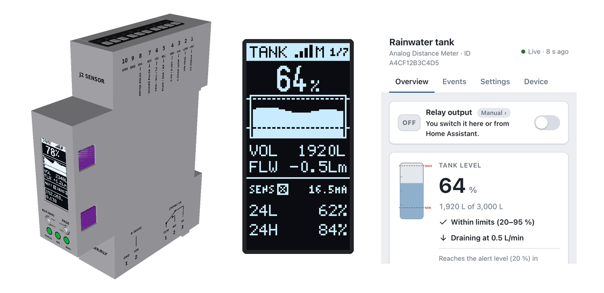
Rendered from the sources: enclosure CAD, the firmware's own OLED drawing code and the web UI (how).
Status: hardware v1 is designed and passes DRC, footprint and fit checks, but no board has been built or tested yet. The firmware builds and its unit tests pass in CI.
Contents: Hardware · Screens · Connecting the sensors · Alerts and relay · Setup · Home Assistant and MQTT · Build, flash, test
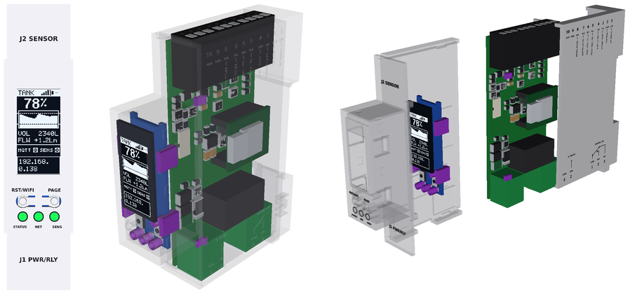
| Enclosure | 1 DIN module (18 mm) printed clamshell, or a wall-mount box with the display on its face; terminals on top (sensors) and bottom (power, relay) |
| Controller | Seeed XIAO ESP32-C6 on sockets, 4-layer main + UI boards (one breakaway panel) |
| Power | 9–30 V DC (24 V nominal), reverse and surge protected, 5 V / 600 mA buck |
| Inputs | 10-pole push-in sensor bank: 4–20 mA (120 Ω shunt, 50 mA fuse), 0–10 V, four protected digital lines (ultrasonic, Geiger pulses, meter pulses, I²C/UART), +24 V / +5 V sensor supply |
| Output | Relay, COM / NO / NC, 230 VAC up to 2 A, off at power-up |
| Front | 0.96" 64×128 OLED, PAGE and RST/WIFI buttons, STATUS / NET / SENS LEDs |
Full design, BOM, ordering files, wiring examples, mains-safety notes and open items: hardware/releases/v1.
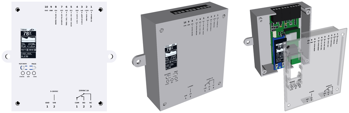
The same boards in a 26 × 81 × 70 mm box with screw ears: the main board drops into a tray, the UI board is turned to face the lid beside the terminal legend, and the lid is held by four M3 screws. Files and assembly: box_enclosure and the release notes.
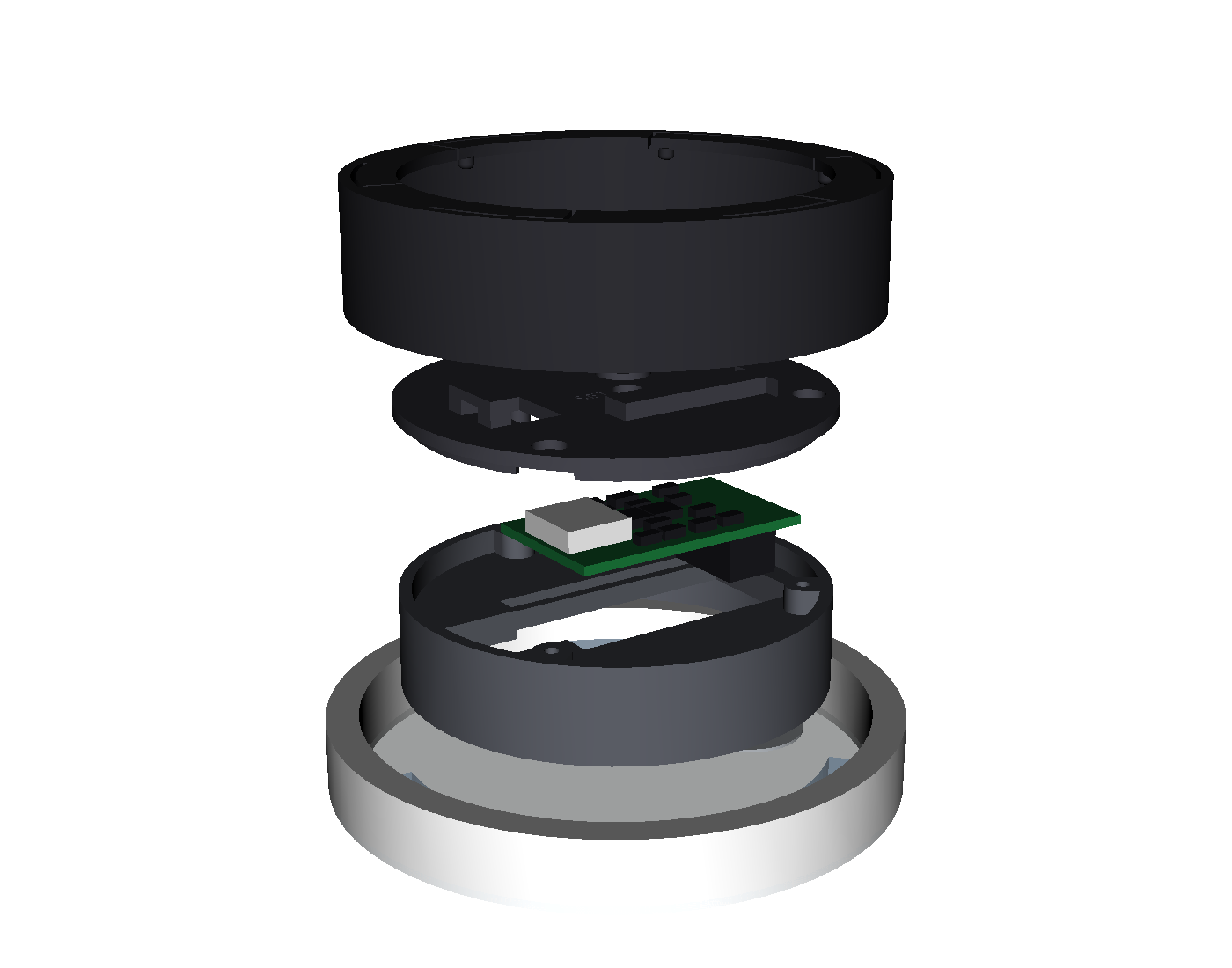
Optical dial reader: carrier, board, lid and lock ring (separate PCB).
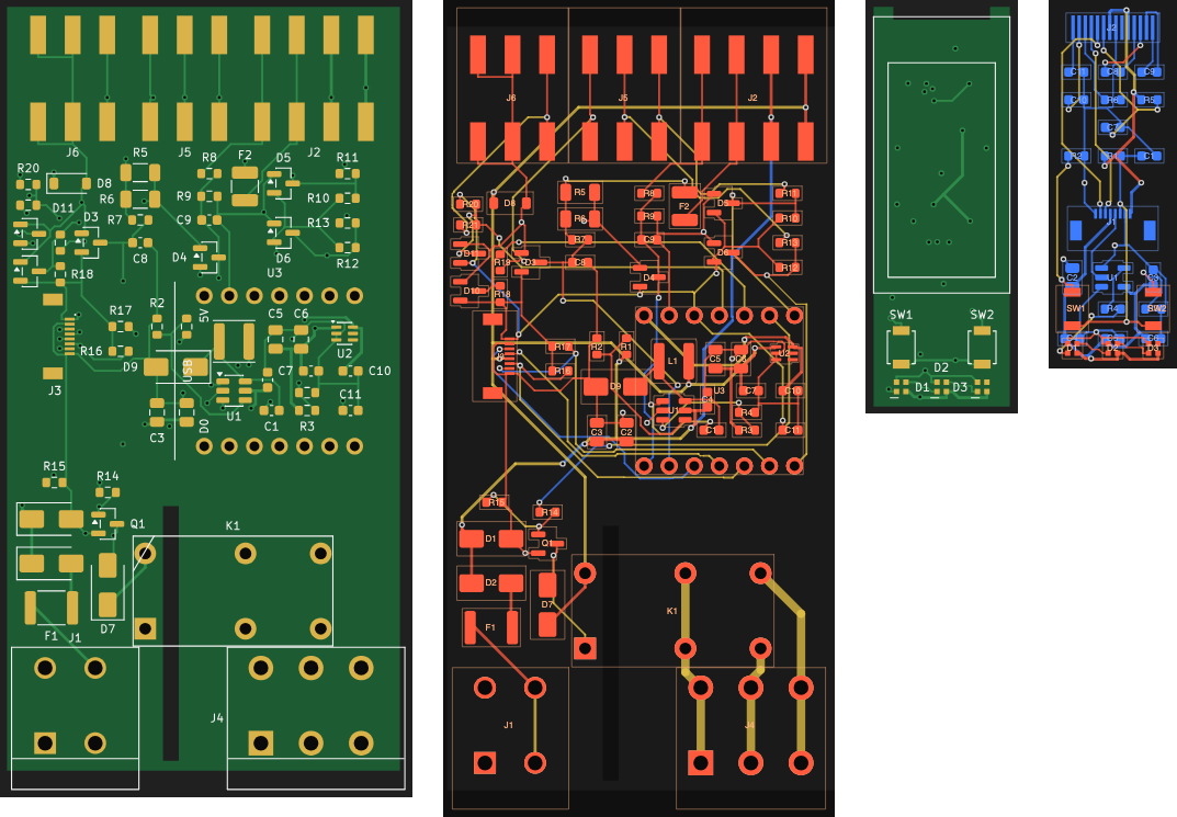
Main board (top, copper) and UI board (top, copper), same scale.
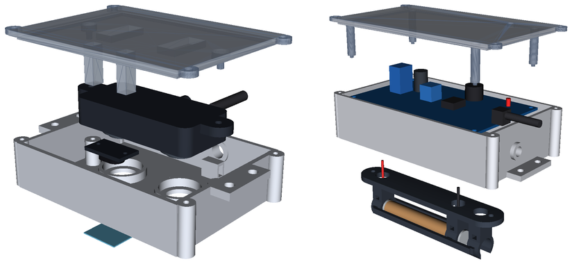
Printable accessories: lid-mount distance sensor pod and the radiation counter duct mount.
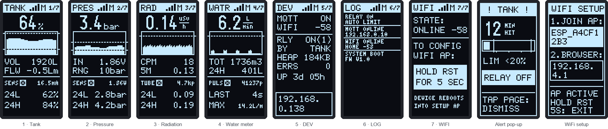
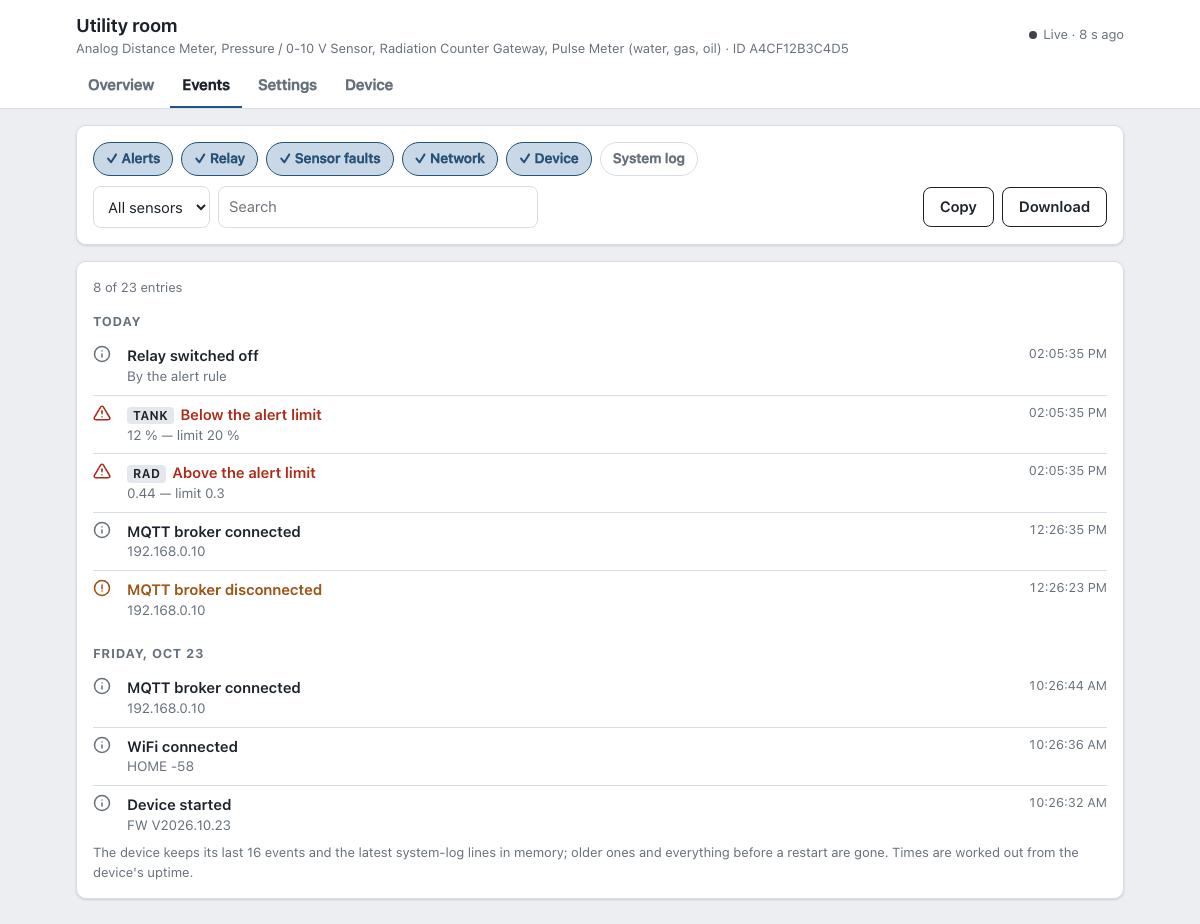
Each running sensor has one page: its reading with a 56-point trend and its alert limits as dotted lines, two secondary values, then its own diagnostics: sensor state and terminal signal, plus two rows, the 24 h low/high, or for a pulse meter the time since the last pulse and the 24 h peak flow (its 24 h low is always 0). Device-wide information is shown once instead of on every sensor page: DEV has MQTT, WiFi, the relay and which sensor drives it, memory, errors, uptime and the IP; LOG the last device events; WIFI how to reach the setup portal. Every header shows the WiFi bars, an M while the MQTT broker is connected (gone when it is not) and the page number. An alert pops up, naming its sensor, until PAGE is pressed. If the first board shows the image upside down, set DISPLAY_ROTATION to 3 in lib/Display/Display.cpp.
Served by the device itself and built per sensor type, following the high-performance HMI guidelines (ISA-101): neutral greys, colour only for abnormal states, and every value shown against its normal and alert range.
| Tank | Pressure | Radiation, alert active |
|---|---|---|
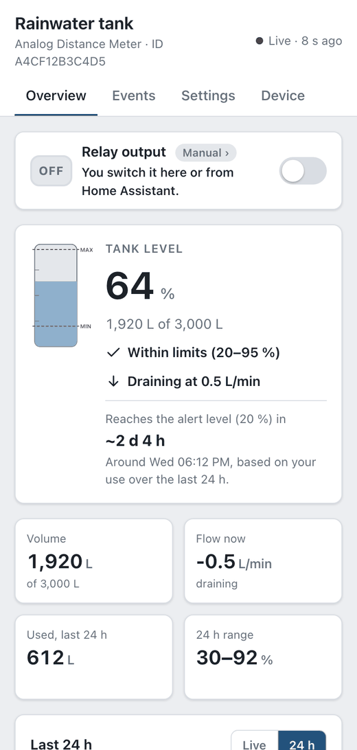 | 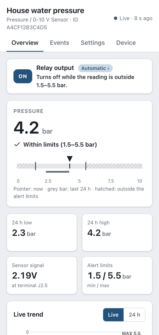 | 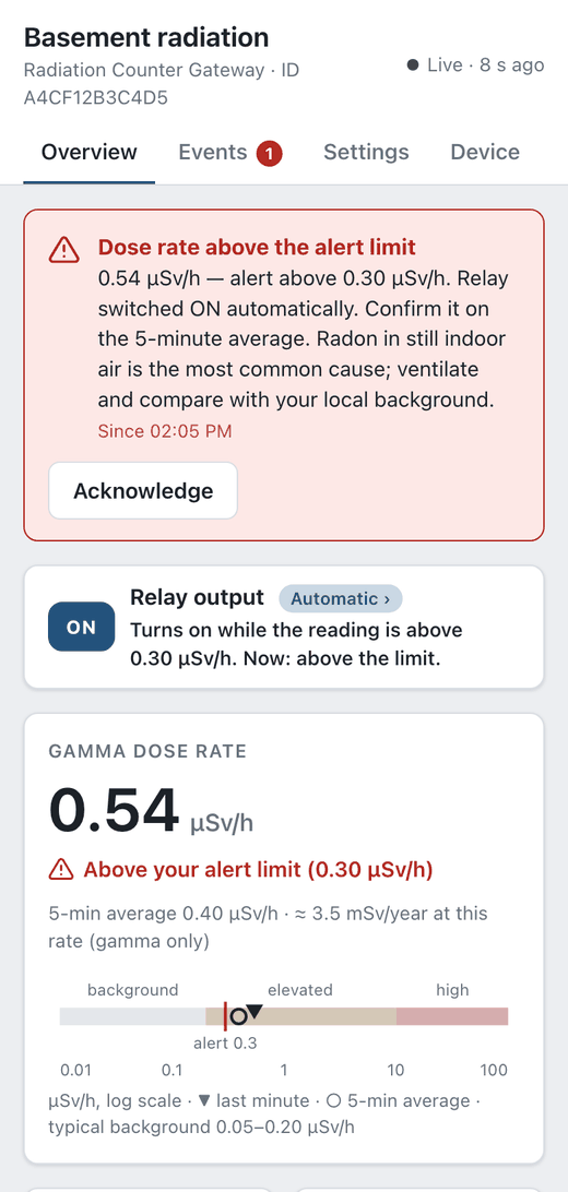 |
| Forecast of when the tank reaches the alert level, from the last 24 h of use | Moving scale with the alert band and the 24 h range | Alert with acknowledge; dose on a log scale with published bands |
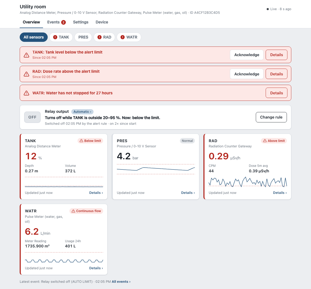
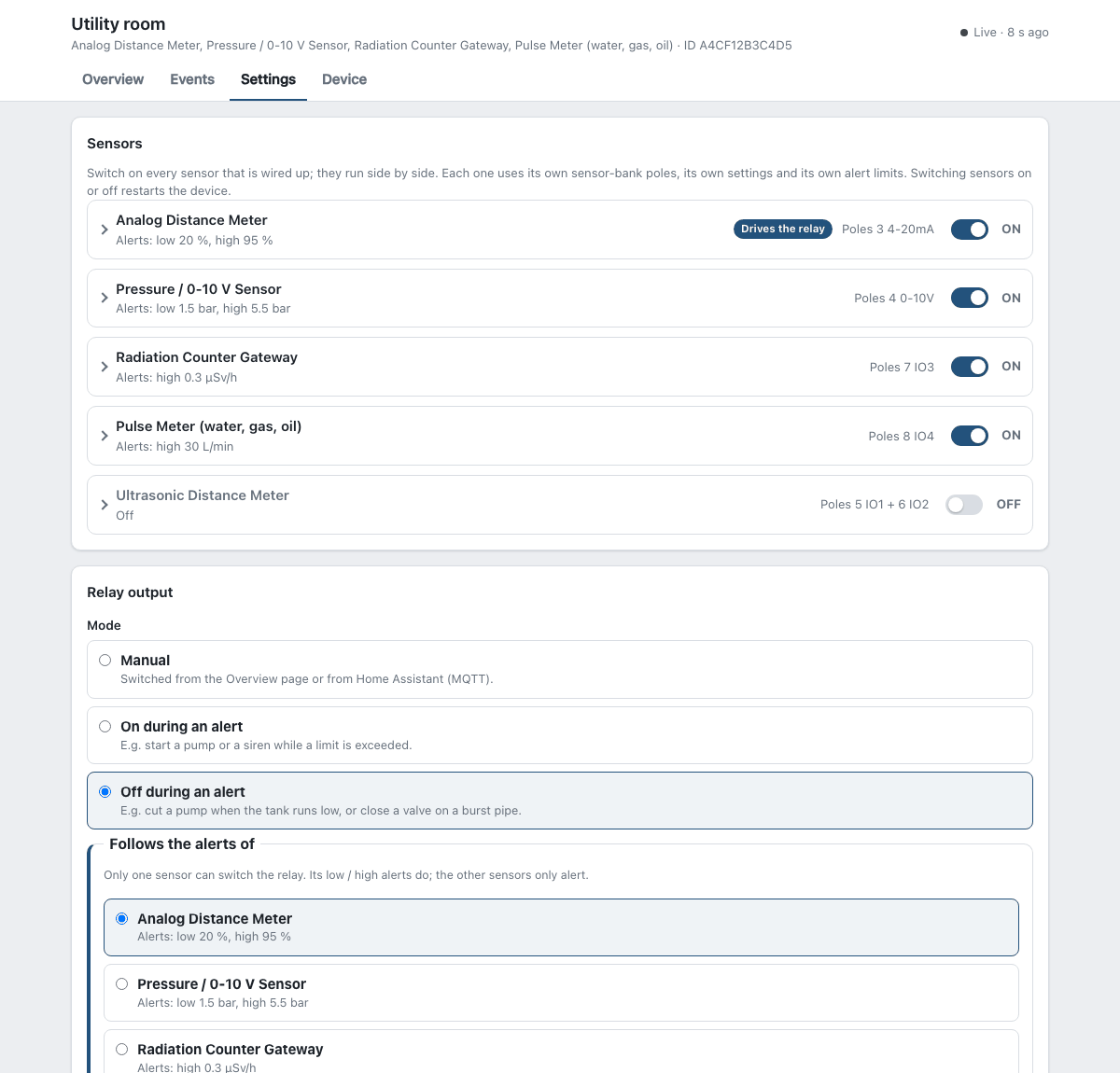
#overview/<sensor id>).GET /api/v1/status (also pushed as the WebSocket stats_update event): device fields (relay with its source sensor, events, configured, errors, warnings, uptime_s) and sensors[], one per running sensor: id, name, configured, screen (with kind: level / pressure / radiation / meter / voltage), stats[] ({key, label, value, numeric}), limits.GET /api/v1/chart?sensor=<id>: that sensor's 24 h history (points, span_seconds, unit); the first sensor without sensor.GET /api/v1/config: device settings and every sensor type with enabled, inputs (poles), prefix, topic, params and limits. POST /api/v1/config takes sensors ("analog_distance,pulse_meter") and the sensors' settings under their prefix (ad.distance_empty, pm.limit_high, ...); unknown sensors or two on one input are refused with 400.POST /api/v1/relay?state=on|off (409 while an alert rule controls the relay), POST /api/v1/alert/ack[?sensor=<id>] (without sensor: every pending alert), POST /api/v1/restart, POST /api/v1/reset, POST /api/v1/upload (firmware).Any combination of the five sensors can run at once, since each uses its own poles (they share +5V and GND; use twin ferrules where two wires share a pole). In the web UI under Settings → Sensors, switch on each one you have wired up, fill in its settings and save (the device restarts). Each sensor samples and publishes on its own interval.
| Terminal | Pole | Use |
|---|---|---|
| Terminal | Pole | Use |
| --- | --- | --- |
| J1 (bottom) | 1 GND · 2 VIN | Power in, 9–30 V DC. Use 24 V for 4–20 mA probes. |
| Sensor bank (top, 3.5 mm push-in) | 1 +5V | Sensor supply, 5 V, shared 600 mA budget with the controller |
| 2 +24V | Sensor supply: the J1 input voltage after the fuse and reverse-polarity diode (about VIN − 0.5 V) | |
| 3 4-20mA | 4–20 mA loop input (120 Ω shunt, 50 mA resettable fuse) | |
| 4 0-10V | Voltage input, 0–10 V | |
| 5 IO1 | Digital: ultrasonic ECHO | |
| 6 IO2 | Digital: ultrasonic TRIG | |
| 7 IO3 | Digital: Geiger counter pulse | |
| 8 IO4 | Digital: meter pulses (dial reader, pulse modules, reed contacts) | |
| 9, 10 GND | Sensor ground | |
| J4 (bottom) | 1 COM · 2 NO · 3 NC | Relay output, 230 VAC ≤ 2 A, fused; see Alerts and relay and the mains notes |
ultrasonic_distance)| Sensor pin | Terminal |
|---|---|
| VCC (5V) | 1 +5V |
| GND | 9 GND |
| TRIG | 6 IO2 |
| ECHO | 5 IO1 |
analog_distance)| Probe wire | Terminal |
|---|---|
| Red (+) | 2 +24V |
| Black (−) | 3 4-20mA |
| Shield, if any | 10 GND (at the box end only) |
measured value (in m) on the MQTT state topic, or from the Overview's Sensor to surface tile while Total Volume is still empty.analog_voltage)| Sensor wire | Terminal |
|---|---|
| Supply + | 1 +5V (5 V sensors, e.g. ratiometric 0.5–4.5 V) or 2 +24V (sensors rated 9–30 V supply) |
| GND / − | 9 or 10 GND |
| Signal / output | 4 0-10V |
radiation_counter)| CAJOE pin (P3 header) | Terminal |
|---|---|
| 5V | 1 +5V |
| GND | 9 or 10 GND |
| VIN (this is the pulse output, despite its name) | 7 IO3 |
RadiationCounterPlugin.cpp), so calibrate against a reference instrument when accuracy matters.pulse_meter)Counts one pulse per K litres on IO4 from any meter that gives pulses:
Settings:
1666.623).
Optical dial reader (our own add-on). A reflective IR sensor watches a meter's metal half-disc or pointer through flat glass, so it needs no battery and no pre-equipped meter. It's built for a B METERS GMDM water dial but suits any dial with a reflective wheel and similar hooks.
hardware/releases/v1/reader/, 31.5 × 18 mm, ordered separately.accessories/dial_reader/, three printed parts, 16.4 mm tall in total:
| Reader terminal (WAGO 2059, solid 0.14–0.34 mm²) | Sensor bank |
|---|---|
| 1 +5V | 1 +5V |
| 2 GND | 9 or 10 GND |
| 3 PULSE | 8 IO4 |
dial_reader_test_ring.stl first. Set it on the glass with its tabs beside the hooks and turn it counter-clockwise until it stops; it should not lift off.Instead, a B METERS IWM-PL3 pulse module: white wire → 8 IO4, brown → 9 or 10 GND; insulate the yellow (tamper) and green (backflow) wires. It runs on its own battery.
-I versions (GMDM-I, GMB-RP-I, GMB-I).Every sensor has its own low and high alert in Settings → Sensors, each with an ON/OFF switch and a value in the unit of its main reading (% for tanks, the sensor unit for pressure, µSv/h for radiation, L/min for meters), plus a clear margin (hysteresis). The relay is either manual (web UI, MQTT, Home Assistant) or follows the alerts of one sensor chosen under Settings → Relay output (on or off during an alert, e.g. a siren, dry-run protection or closing a valve on a burst pipe); the other sensors only alert. While a rule owns the relay, manual commands are refused, and a sensor fault holds the last state. Changes apply without a restart.
ESP_<ChipID> (the OLED shows the name). Join it and enter your WiFi; the device restarts.Home Assistant discovers one device through the MQTT integration: the entities of every running sensor, plus the heap/RSSI/uptime diagnostics and the relay switch once for the device. Sensor entity ids start with the sensor id (analog_distance, pulse_meter_total, ...), so sensors side by side never collide.
<device_name>/stat/<plugin_id>   one per running sensor: its measurements, at its publish interval
<device_name>/diag               device: heap, RSSI, uptime, version (every 30 s)
<device_name>/availability       LWT: "online" / "offline"
<device_name>/relay              relay state ON / OFF
<device_name>/relay/set relay command ON / OFF{ "relative": 0.73, "absolute": 1.12, "measured": 1.51, "raw": 1.55, "connected": true,
"volume": 2340, "flow_rate": 0.42, "usage_24h": 187.3 }
{ "value": 3.4, "voltage": 1.86, "connected": true }
{ "cpm": 42, "dose": 0.34, "dose_avg_5m": 0.29, "counts_total": 183412, "alert": false }
{ "state": "active", "heap": 41520, "rssi": -62, "uptime_s": 3602, "version": "v2026.09.03.2214" }Distance: volume, flow_rate and usage_24h only when Total Volume is set. The firmware version is the HA device's sw_version.
Target: xiao_c6 (USB) / xiao_c6_ota (network) for the v1 board, built with the pioarduino platform (Arduino-ESP32 3.x).
# In Docker, as CI does (PlatformIO Core pinned to 6.1.19)
docker build -f Dockerfile.firmware -t esp-firmware .
docker run --rm -v "$PWD":/project -v esp-pio:/root/.platformio esp-firmware "pio run -e xiao_c6"

pio run -e xiao_c6 -t upload                                  # USB
pio run -e xiao_c6_ota -t upload --upload-port <DEVICE_IP>    # OTA (espota)
pio test -e native # unit tests on the hostfirmware.bin: for Device → Firmware update in the web UI; it includes the web UI (tools/embed_web.py gzips data/ into it) and keeps settings. The device refuses the other file here.firmware-full-usb.bin: bootloader, partition table and app in one file for an empty or bricked board over USB: esptool --chip esp32c6 write-flash 0x0 <file> or the browser flasher. It erases saved settings.python3 tools/webui_mock.py, then open http://127.0.0.1:8790/?sensor=tank (scenarios: tank, tank-basic, tank-alarm, pressure, radiation, radiation-high, fault)../setup-ide.sh generates compile_commands.json and .clangd for clangd..github/workflows/ci.yml); releases attach both images.python3 tools/readme_images/render.py rebuilds everything in doc/images/: the OLED pages from lib/Display through the real U8g2 code, the web UI from data/ via the mock and headless Chrome, and crops of the hardware renders in hardware/releases/v1. Needs Pillow, Chrome and one prior pio run -e xiao_c6.
| Qty | Value | Footprint | References |
|---|---|---|---|
| 3 | 100n 50V | Capacitor_SMD:C_0603_1608Metric | C2, C3, C4 |
| 1 | 10k | Potentiometer_SMD:Potentiometer_Bourns_TC33X_Vertical | RV1 |
| 1 | 10k | Resistor_SMD:R_0603_1608Metric | R3 |
| 1 | 10u 10V | Capacitor_SMD:C_0603_1608Metric | C1 |
| 1 | 1k | Resistor_SMD:R_0603_1608Metric | R5 |
| 1 | 2059-303/998-403 | gateway_fp:TerminalBlock_WAGO_2059-303_SMD | J1 |
| 1 | 220R | Resistor_SMD:R_0603_1608Metric | R1 |
| 1 | 330R | Resistor_SMD:R_0603_1608Metric | R6 |
| 1 | 390k | Resistor_SMD:R_0603_1608Metric | R4 |
| 1 | 4k7 | Resistor_SMD:R_0603_1608Metric | R2 |
| 1 | B5819W | Diode_SMD:D_SOD-123 | D1 |
| 1 | LMV331 | Package_TO_SOT_SMD:SOT-23-5 | U2 |
| 1 | TCRT5000 | gateway_fp:Vishay_TCRT5000_Clips | U1 |
| 1 | red | LED_SMD:LED_0805_2012Metric | D2 |
It measures 31.5 × 18 mm and has 4 copper layers, 1.2 mm thick.
16 parts, built around the LMV331TP, TCRT5000 and B5819W. The full list of its parts is on this page, with links to each part's symbol and footprint where PCBKit's library has them.
From the vbartusevicius/esp-measurement-platform repository on GitHub, at the commit this page was made from: the board is hardware/layout/v1/reader/reader.kicad_pcb. PCBKit opens the board in the browser, with nothing to install.
Its repository states no licence, so its author keeps all rights: ask vbartusevicius before reusing the design.
vbartusevicius/esp-measurement-platform
Modular ESP measurement platform with HomeAssistant and MQTT integration.

vbartusevicius/esp-measurement-platform
Modular ESP measurement platform with HomeAssistant and MQTT integration.

vbartusevicius/esp-measurement-platform
Modular ESP measurement platform with HomeAssistant and MQTT integration.

tadzio8425/Micromouse
Micromouse developed by the IEEE Robotics and Automation Society chapter of the Universidad de Los Andes, Bogotá (2023-2024).


mariusenglund/three-phase-inverter
Materials for enhancing the DC-to-AC converter that was designed as part of our bachelor's thesis in the spring of 2023.


lucasbaizer/pico-2v
RP2354A development board with switchable voltage, QSPI breakout, and more

ajisrawi/sentinel-uhf-radar
Reference design of a two-face UHF early-warning phased-array radar: system sizing, MoM antenna simulation, seven KiCad PCB projects, Blender site model

