2 layers38.1 × 63.5 mm
Sstv backpack v1.1
vaugerbird/sstv-backpack
A ESP32-CAM SSTV backpack for the Baofeng UV-5R + others!
28 parts94GPL-2.0

 vaugerbird/sstv-backpack94
A ESP32-CAM SSTV backpack for the Baofeng UV-5R + others!
Sstv backpack is an open-source printed circuit board by vaugerbird, from the vaugerbird/sstv-backpack repository on GitHub, published under the GPL-2.0 licence. It is a 2-layer board of 38.1 × 63.5 mm with 29 parts on 39 nets, routed with 162 tracks and 10 vias.
It is built around the ESP32-CAM, FT231XS-R and CPT-9019B-SMT-TR, with the LM2940IMPX-5.0/NOPB-HXY, MMBT3904 and SLW-1276864-4A-D among its other parts. Its parts include 6 capacitors, 5 resistors, 4 diodes, 3 connectors and 2 ICs. It belongs with the ESP32 and RISC-V boards of this library.


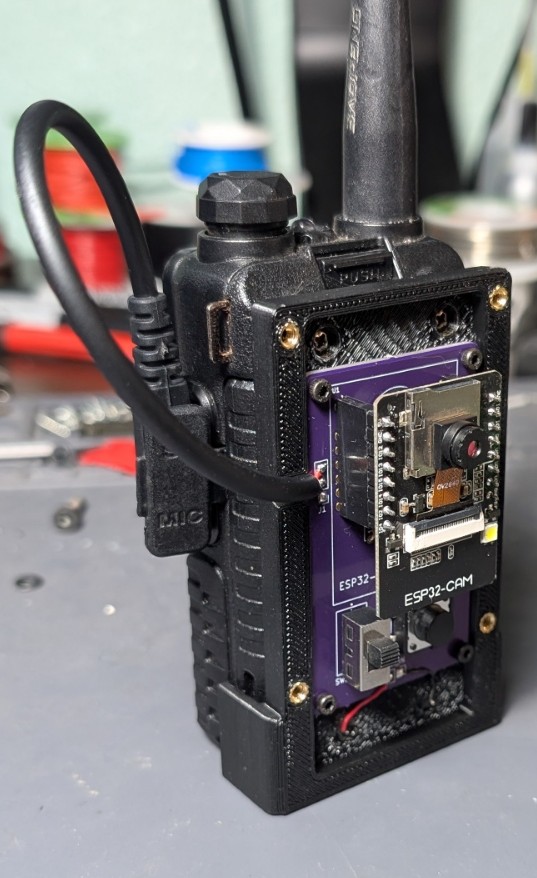
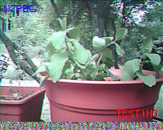
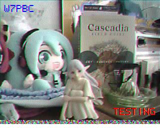
This project relies on using an ESP32 connected to a handheld transceiver to send SSTV (Slow Scan TeleVision) images. Any combination of HT and ESP32-CAM can send a picture, but the hardware in this repository is specifically designed to work!
To decode the images, another radio must be used and connected to any device that can run a decoder program. I personally use MMSSTV on my PC with a USB soundcard, or my phone running Robot36 and listening to the radio with the microphone.
Here's some questions I've been asked in the past:
I currently have 2 hardware revisions available, with a 3rd planned:
Upload your desired Gerber file to your favorite PCB manufacturer. I recommend OSHPark for US-made, decent-priced priced small-batch PCBs. JLCPCB or PCBWay are both great for cheap, high quality PCBs, if you don't mind waiting.
Order the required parts using the proper BOM for v1.0 or v1.1 from your favorite parts supplier.
Once all parts arrive, assemble the board. There isn't much of a technique to it, just start with the lowest profile parts first like the diodes, resistors, and chips, and work your way up.
Once the board is complete, print the case using one of the included STLs. Currently, the Baofeng UV-5R is the only supported radio, but the Inventor 2025 and STEP files are included, and help with additional radio models is always appreciated!
I used the standard settings (0.2mm) on my print, with supports on, and the case interior facing the build plate.
The case requires these additional parts:
After you have the hardware assembled, the next thing to do is upload the code!
https://dl.espressif.com/dl/package_esp32_index.jsonFrom the board manager, install the newest version of the ESP32 board definitions.
Set the board model to "AI Thinker ESP32-CAM" and select the appropriate COM port.
Change the text options on lines 37 and 38 of sstv-backpack.ino to reflect your callsign and desired splash text.
Uncomment line 21 #define USE_FLASH if you want to use the flash LED (Turns on a high intensity white LED on when framegrabbing).
At line 447, set 1 = HIGH or 0 = LOW properly reflect your CAPT_BTN wiring (GND for LOW, or +3.3V for HIGH)
Between line 452-456, choose the correct button pull-up/pull-down configuration. The button is set to pull-up by default to mirror the PCBs. (Button connects to GND when pressed)
Inside the "camera.h" file you can choose between two profiles, DAYLIGHT and HOME. Feel free to modify settings to best suit your case.
All the board settings can be left alone except for selecting the correct COM port.
Upload the code!
A huge thank you to our contributors for this project! I'm pretty bad with code so all help is greatly appreciated!
| Qty | Value | Footprint | References |
|---|---|---|---|
| 2 | 1N4148 | Diode_SMD:D_SOD-123 | D3, D4 |
| 2 | 1N5819 | Diode_SMD:D_SOD-123 | D1, D2 |
| 2 | 27Ω | Resistor_SMD:R_0805_2012Metric_Pad1.20x1.40mm_HandSolder | R1, R2 |
| 2 | 4.7k | Resistor_SMD:R_0805_2012Metric_Pad1.20x1.40mm_HandSolder | R3, R4 |
| 2 | 47pF | Capacitor_SMD:C_0805_2012Metric_Pad1.18x1.45mm_HandSolder | C3, C4 |
| 1 | 0.47uF | Capacitor_SMD:C_0805_2012Metric_Pad1.18x1.45mm_HandSolder | C2 |
| 1 | 100nF | Capacitor_SMD:C_0805_2012Metric_Pad1.18x1.45mm_HandSolder | C6 |
| 1 | 10k | Resistor_SMD:R_0805_2012Metric_Pad1.20x1.40mm_HandSolder | R5 |
| 1 | 10nF | Capacitor_SMD:C_0805_2012Metric_Pad1.18x1.45mm_HandSolder | C5 |
| 1 | 22uF | Capacitor_SMD:C_0805_2012Metric_Pad1.18x1.45mm_HandSolder | C1 |
| 1 | CPT-9019B-SMT-TR | Buzzer_Beeper:Buzzer_CUI_CPT-9019S-SMT | BZ1 |
| 1 | Conn_01x02_Pin | Connector_PinHeader_2.54mm:PinHeader_1x02_P2.54mm_Vertical | J2 |
| 1 | Conn_01x03_Pin | Connector_PinHeader_2.54mm:PinHeader_1x03_P2.54mm_Vertical | J1 |
| 1 | ESP32-CAM | ESP32-CAM:ESP32-CAM | U1 |
| 1 | FT231XS | Package_SO:SSOP-20_3.9x8.7mm_P0.635mm | U2 |
| 1 | LM2940IMPX-5.0/NOPB | Package_TO_SOT_SMD:SOT-223-3_TabPin2 | VR1 |
| 1 | MMBT3904 | Package_TO_SOT_SMD:SOT-23 | Q1 |
| 1 | SLW-1276864-4A-D | SwitchSPDT:SW_SLW-1276864-4A-D | SW2 |
| 1 | SW_Push | Button_Switch_SMD:SW_Push_1P1T_NO_CK_PTS125Sx43PSMTR | SW1 |
| 1 | USB_C_Receptacle_USB2.0_14P | Connector_USB:USB_C_Receptacle_GCT_USB4085 | J4 |
The 25 most common of 29 parts.
vaugerbird/sstv-backpack
A ESP32-CAM SSTV backpack for the Baofeng UV-5R + others!

vaugerbird/sstv-backpack
A ESP32-CAM SSTV backpack for the Baofeng UV-5R + others!

vaugerbird/sstv-backpack
A ESP32-CAM SSTV backpack for the Baofeng UV-5R + others!

vaugerbird/sstv-backpack
A ESP32-CAM SSTV backpack for the Baofeng UV-5R + others!

PumpkinClouds/Ford_F150_Raptor_SumoBot_AL_Trim
Bot code and pcb for sumo bot competition. (Asgore's fault)


AeroX2/aerox2.github.io
One repository and npm installation builds the workshop at jamesridey.dev and the professional site at cv.jamesridey.dev.


chasestuard07/Breathing-LED-Heart-PCB
Custom battery-powered PCB featuring LEDs that turn on and off with a breathing effect.

Dooganar/engg3800-t3-eaar-pcb-design
A repo used to track and collaborate on the pcb design for the University of Queensland "Team Project II" course.
It measures 38.1 × 63.5 mm and has 2 copper layers, 1.6 mm thick.
29 parts, built around the ESP32-CAM, FT231XS-R, CPT-9019B-SMT-TR and LM2940IMPX-5.0/NOPB-HXY. The full list of its parts is on this page, with links to each part's symbol and footprint where PCBKit's library has them.
From the vaugerbird/sstv-backpack repository on GitHub, at the commit this page was made from: the board is hardware/v1.2/sstv-backpack.kicad_pcb and its schematic hardware/v1.0/Old v1.0.0 Files/sstv-backpack-v1.0.0.kicad_sch. PCBKit opens the board in the browser, with nothing to install.
Its repository publishes it under the GPL-2.0 licence: you may reuse it on that licence's terms (keep the author's notice, and for a copyleft licence share your changes alike).