
2 layers60.1 × 60 mm
Adhdv1.00
Maxwell-Khor/adhd-medication-reminder
Custom embedded medication reminder device with PCB design and firmware development for improving medication adherence
82 parts

 VarunAPatil/MedSafe
The goal: a compact, wrist-worn device that simultaneously tracks heart rate & SpO₂, motion & orientation, altitude & atmospheric pressure, and GNSS location — all in one tightly integrated system.
Watch is an open-source printed circuit board by VarunAPatil, from the VarunAPatil/MedSafe repository on GitHub. It is a 4-layer board with 121 parts on 120 nets, routed with 543 tracks and 64 vias.
It is built around the ESP32-PICO-D4, BMP388 and DRV2605LDGS, with the W25Q128JVSIQ, BQ24074RGTR and LSM6DS3 among its other parts. Its parts include 38 capacitors, 37 resistors, 12 ICs, 8 diodes and 5 transistors. It belongs with the wearables boards and the ESP32 and RISC-V boards of this library.


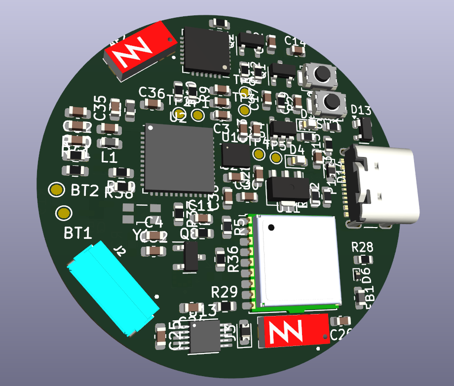
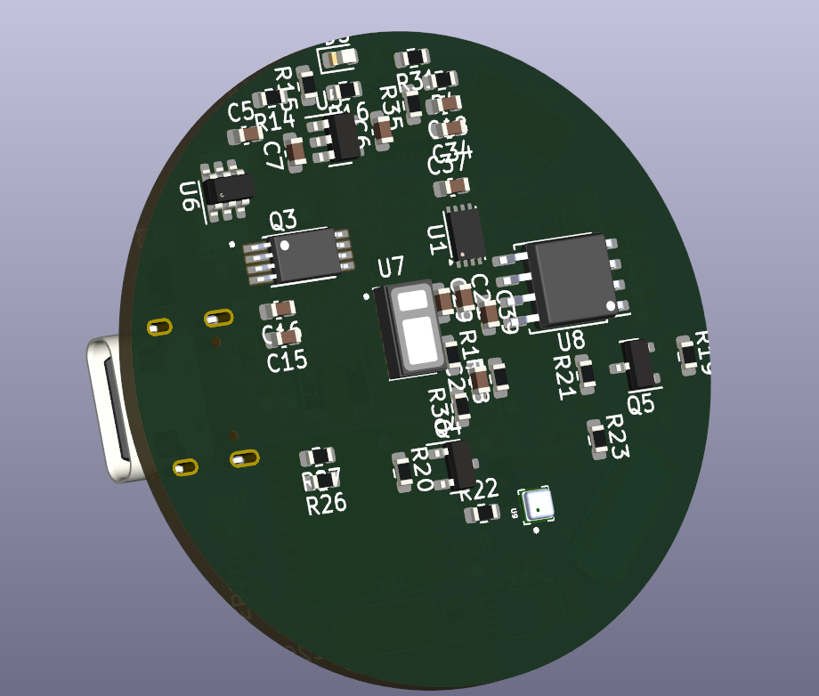



MedSafe is a custom-designed smartwatch platform engineered for real-time health and environmental monitoring. The project spans the full hardware–firmware stack — from KiCad schematics and custom PCB footprints all the way to a modular, multi-sensor ESP-IDF firmware that runs a synchronized 50 Hz acquisition loop across four independent sensors.
The goal: a compact, wrist-worn device that simultaneously tracks heart rate & SpO₂, motion & orientation, altitude & atmospheric pressure, and GNSS location — all in one tightly integrated system.
| Feature | Details |
|---|---|
| ❤️ Heart Rate & SpO₂ | MAX30102 optical pulse oximeter with AGC and peak-detection |
| 📐 6-DoF IMU | LSM6DSO accelerometer + gyroscope with tilt computation & sensor fusion |
| 🌡️ Barometric Pressure | BMP388 barometer with temperature compensation and altitude derivation |
| 🛰️ GNSS Navigation | MAX-M10S GPS module via UBX protocol — fix type, coordinates, speed & UTC |
| ⚡ 50 Hz Sensor Loop | FreeRTOS task pinned to Core 0, all sensors polled in a tight 20 ms cycle |
| 🔌 Shared I2C Bus | Single i2c_manager abstraction used by all four sensor drivers |
| 🔋 Battery Management | BQ24074RGTR Li-Ion charger with FS8205A battery protection FET |
| 📳 Haptic Feedback | DRV2605L LRA/ERM haptic driver |
| 💾 Flash Storage | W25Q128/W25Q64 NOR Flash over SPI |
MedSafe/
│
├── 📁 Firmware/                  # ESP-IDF firmware projects
│   ├── 📁 Integration/           # ★ Main multi-sensor integration firmware
│   │   └── main/
│   │       ├── main.c            # App entry & 50 Hz sensor loop
│   │       ├── src/              # Sensor driver implementations
│   │       │   ├── i2c_manager.c
│   │       │   ├── bmp388.c
│   │       │   ├── lsm6dso.c
│   │       │   ├── max30102.c
│   │       │   └── max_m10s.c
│   │       └── include/          # Public driver headers
│   │           ├── i2c_manager.h
│   │           ├── bmp388.h
│   │           ├── lsm6dso.h
│   │           ├── max30102.h
│   │           └── max_m10s.h
│   │
│   ├── 📁 Barometer/             # Standalone BMP388 firmware
│   ├── 📁 IMU/                   # Standalone LSM6DSO firmware
│   ├── 📁 PulseSensor/           # Standalone MAX30102 firmware
│   └── 📁 max_m10s/              # Standalone GNSS firmware
│atan20x6A / 0x6B) with automatic fallbackUBX-NAV-PVT messages for:
app_main()
    │
    ├── i2c_manager_init()        ← Shared bus (GPIO 8 SDA / GPIO 9 SCL)
    ├── bmp388_init()
    ├── lsm6dso_init() + calibrate()
    ├── max30102_init()
    ├── max_m10s_init()
    │
    └── xTaskCreatePinnedToCore()
            │
            └── sensor_integration_task()   [Core 0 @ 50 Hz]
                    │
                    ├── bmp388_read_temperature_pressure()
                    ├── lsm6dso_read_data() → lsm6dso_compute_tilt()
                    ├── max30102_read_fifo() → AGC / BPM / SpO₂
                    ├── max_m10s_read_nav_pvt()   [every 50 loops ≈ 1 s]
                    └── printf() combined report   [every 5 loops ≈ 100 ms]
The i2c_manager is a thin singleton that wraps ESP-IDF's i2c_master with mutex-protected register read/write helpers. All four sensor drivers call into it exclusively — no direct I2C calls exist in driver code.
cd Firmware/Integration

# Set the target
idf.py set-target esp32

# Configure (optional)
idf.py menuconfig

# Build, flash, and monitor
idf.py build flash monitorEach sensor subdirectory (Barometer/, IMU/, PulseSensor/, max_m10s/) is an independent ESP-IDF project and can be built identically:
cd Firmware/Barometer
idf.py set-target esp32
idf.py build flash monitor| Signal | GPIO |
|---|---|
| I2C SDA | GPIO 8 |
| I2C SCL | GPIO 9 |
All four sensors share the same I2C bus. Sensor I2C addresses:
| Sensor | I2C Address |
|---|---|
| BMP388 | 0x77 (secondary) |
| LSM6DSO | 0x6A / 0x6B |
| MAX30102 | 0x57 |
| MAX-M10S | 0x42 (default) |
| Component | Part | Function |
|---|---|---|
| MCU | ESP32-PICO-D4 | Dual-core 240 MHz with integrated antenna |
| IMU | LSM6DSO | 3-axis accel + gyro |
| Barometer | BMP388 | Pressure + temperature |
| Pulse Oximeter | MAX30102 | PPG / SpO₂ / HR |
| GNSS | MAX-M10S | Multi-band GNSS receiver |
| Battery Charger | BQ24074RGTR | 1A Li-Ion charger |
| Battery Protect | FS8205A | Dual-FET protection |
| Haptic Driver | DRV2605L | LRA/ERM haptic feedback |
| Flash | W25Q128 / W25Q64 | 128/64 Mbit NOR Flash |
| Crystal | ECS-400-10-37B2 | 32.768 kHz RTC crystal |
Full BOM available at PCB_Files/watch.csv.
The hardware design lives in PCB_Files/ and is a complete KiCad 7 project:
watch.kicad_sch — Full hierarchical schematicwatch.kicad_pcb — Routed PCB layout with 3D model referenceswatch.kicad_pro — Project configuration and design rulesfootprints_schematics/ — Custom footprint libraries for non-standard packages (e.g., MAX-M10S, MAX30102, FS8205A)Open in KiCad 7+ for schematic review or PCB manufacturing export (Gerbers, drill files).
This project is licensed under the MIT License. See LICENSE for details.
Built with ❤️ using ESP-IDF, KiCad, and a lot of patience debugging I2C.
| Qty | Value | Footprint | References |
|---|---|---|---|
| 16 | 10k | Resistor_SMD:R_0603_1608Metric | R2, R4, R5, R7, R11, R12, R22, R23, R29, R31, R32, R38, R39, R40, R41, R43 |
| 14 | 0.1 uF | Capacitor_SMD:C_0603_1608Metric | C1, C8, C10, C11, C13, C14, C17, C22, C27, C28, C29, C34, C37, C39 |
| 8 | TestPoint | TestPoint:TestPoint_Pad_D1.0mm | TP1, TP2, TP3, TP4, TP5, TP6, TP7, TP8 |
| 5 | 1 uF | Capacitor_SMD:C_0603_1608Metric | C2, C9, C24, C25, C32 |
| 4 | 4.7k | Resistor_SMD:R_0603_1608Metric | R18, R19, R20, R21 |
| 4 | LED | LED_SMD:LED_0603_1608Metric | D2, D4, D7, D8 |
| 3 | 1uF | Capacitor_SMD:C_0603_1608Metric | C23, C30, C31 |
| 3 | 33 | Resistor_SMD:R_0603_1608Metric | R26, R27, R28 |
| 3 | BC847 | Package_TO_SOT_SMD:SOT-23 | Q1, Q2, Q8 |
| 2 | 0R | Resistor_SMD:R_0603_1608Metric | R1, R8 |
| 2 | 1.5k | Resistor_SMD:R_0603_1608Metric | R25, R42 |
| 2 | 10 uF | Capacitor_SMD:C_0603_1608Metric | C19, C21 |
| 2 | 12.5pF | Capacitor_SMD:C_0603_1608Metric | C4, C7 |
| 2 | 22uF | Capacitor_SMD:C_0603_1608Metric | C15, C16 |
| 2 | 5.1k | Resistor_SMD:R_0603_1608Metric | R3, R33 |
| 2 | Antenna_Shield | footprints:XCVR_NN03-320 | AE1, AE2 |
| 2 | BSS138 | Package_TO_SOT_SMD:SOT-23 | Q4, Q5 |
| 2 | SW_Push | Button_Switch_SMD:SW_Push_SPST_NO_Alps_SKRK | SW1, SW2 |
| 1 | 0 F | Capacitor_SMD:C_0603_1608Metric | C12 |
| 1 | 0.1uF | Capacitor_SMD:C_0603_1608Metric | C38 |
| 1 | 0.3k | Resistor_SMD:R_0603_1608Metric | R6 |
| 1 | 1.13k | Resistor_SMD:R_0603_1608Metric | R24 |
| 1 | 1.18k | Resistor_SMD:R_0603_1608Metric | R10 |
| 1 | 1.2 pF | Capacitor_SMD:C_0603_1608Metric | C35 |
| 1 | 1.5 pF | Capacitor_SMD:C_0603_1608Metric | C36 |
| 1 | 1.8 nH | Inductor_SMD:L_0603_1608Metric | L2 |
| 1 | 100 pF | Capacitor_SMD:C_0603_1608Metric | C3 |
| 1 | 10pF | Capacitor_SMD:C_0603_1608Metric | C6 |
| 1 | 1k | Resistor_SMD:R_0603_1608Metric | R37 |
| 1 | 2 nH | Inductor_SMD:L_0603_1608Metric | L1 |
| 1 | 22 | Resistor_SMD:R_0603_1608Metric | R36 |
| 1 | 22.1k | Resistor_SMD:R_0603_1608Metric | R34 |
| 1 | 4.12k | Resistor_SMD:R_0603_1608Metric | R9 |
| 1 | 4.7 uF | Capacitor_SMD:C_0603_1608Metric | C18 |
| 1 | 4.7uF | Capacitor_SMD:C_0603_1608Metric | C33 |
| 1 | 47 pF | Capacitor_SMD:C_0603_1608Metric | C26 |
| 1 | 47.5k | Resistor_SMD:R_0603_1608Metric | R35 |
| 1 | 8pF | Capacitor_SMD:C_0603_1608Metric | C5 |
| 1 | APS6404L-3SQRx-ZR | Package_SON:Winbond_USON-8-1EP_3x2mm_P0.5mm_EP0.2x1.6mm | U1 |
| 1 | BMP388 | footprints:PQFN50P200X200X80-10N | U9 |
| 1 | BQ24074RGT | Package_DFN_QFN:VQFN-16-1EP_3x3mm_P0.5mm_EP1.6x1.6mm | U15 |
| 1 | CP2102N-Axx-xQFN28 | Package_DFN_QFN:QFN-28-1EP_5x5mm_P0.5mm_EP3.35x3.35mm | U3 |
| 1 | Conn_01x02_Pin | Diode_SMD:D_0603_1608Metric | J3 |
| 1 | Conn_01x02_Pin | Connector_PinHeader_1.00mm:PinHeader_1x02_P1.00mm_Vertical | J1 |
| 1 | Conn_01x14_MountingPin | footprints:HRS_FH34SRJ-14S-0.5SH_50_ | J2 |
| 1 | DRV2605LDGS | Package_SO:VSSOP-10_3x3mm_P0.5mm | U13 |
| 1 | ECS-400-10-37B2-CKY-TR | footprints:ECX-1637B2_ECS | XTAL1 |
| 1 | ESP32-PICO-D4 | Package_DFN_QFN:QFN-48-1EP_7x7mm_P0.5mm_EP5.3x5.3mm | U2 |
| 1 | FC-135R 32.7680KA-A3 | footprints:XTAL_KA-A3_EPS | XTAL2 |
| 1 | FerriteBead | Inductor_SMD:L_0603_1608Metric | FB1 |
| 1 | LSM6DS3 | Package_LGA:LGA-14_3x2.5mm_P0.5mm_LayoutBorder3x4y | U10 |
| 1 | MAX-M10S | RF_GPS:ublox_MAX | U11 |
| 1 | MAX30105EFD_T | footprints:14-OESIP | U7 |
| 1 | MCP1700x-120xxMB | Package_TO_SOT_SMD:SOT-89-3 | U12 |
| 1 | NC | Capacitor_SMD:C_0603_1608Metric | D1 |
| 1 | PESD0402-0402T | Diode_SMD:D_SOD-923 | D6 |
| 1 | SP0503BAHT | Package_TO_SOT_SMD:SOT-143 | D13 |
| 1 | SS14FL | footprints:SOD-123FL | D9 |
| 1 | TLV75533PDBV | Package_TO_SOT_SMD:SOT-23-5 | U14 |
| 1 | USB_C_Plug_USB2.0 | Connector_USB:USB_C_Receptacle_GCT_USB4105-xx-A_16P_TopMnt_Horizontal | P1 |
| 1 | W25Q128JVS | footprints:SOIC-8_5.23x5.23mm_P1.27mm | U8 |
121 parts, built around the ESP32-PICO-D4, BMP388, DRV2605LDGS and W25Q128JVSIQ. The full list of its parts is on this page, with links to each part's symbol and footprint where PCBKit's library has them.
From the VarunAPatil/MedSafe repository on GitHub, at the commit this page was made from: the board is PCB_Files/watch.kicad_pcb and its schematic PCB_Files/watch.kicad_sch. PCBKit opens the board in the browser, with nothing to install.
Its repository states no licence, so its author keeps all rights: ask VarunAPatil before reusing the design.
Maxwell-Khor/adhd-medication-reminder
Custom embedded medication reminder device with PCB design and firmware development for improving medication adherence

Tinkerbug-Robotics/TinkerRocket
Model rocket flight computer, ground station, iOS app, and simulation

Luos-io/luos_engine
Open-source and real-time orchestrator for cyber-physical-systems, to easily design, test and deploy embedded applications and digital twins.

dkozel/noisesource-psu
USB powered and controlled supply for RF Noise Sources


Paschalis/fc-plus-sensor-module
FC Plus is a modular add-on board for UAV flight controllers, providing advanced telemetry, GPS, object avoidance (ToF, Sonar, IR), and LED indicators for status feedback.