
2 layers135.3 × 78.4 mm
Mseq
MF-Room/mseq_pcb
KiCad 10 hardware design for MSeq embedded, the microcontroller implementation of the MSeq MIDI sequencer.
93 parts1CERN-OHL-S-2.0

 usimd/water-meter-counter1
Inductive water meter counting module for B-meters GSD8
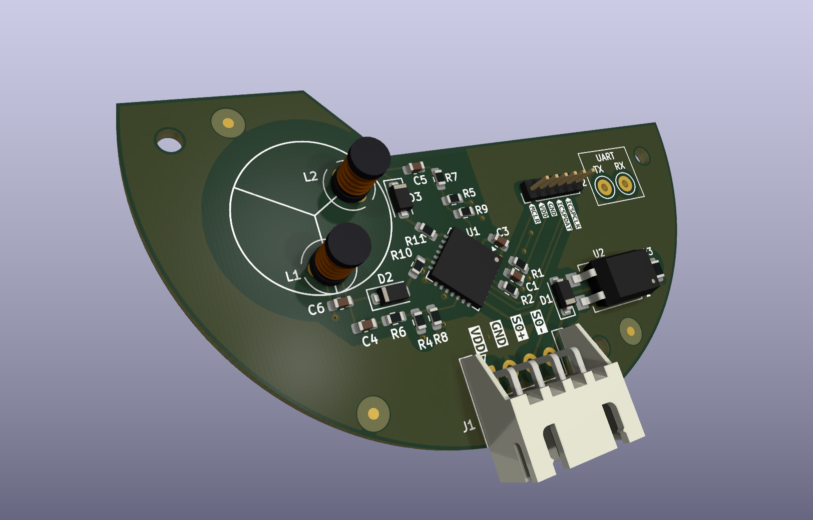
Water meter counter is an open-source printed circuit board by usimd, from the usimd/water-meter-counter repository on GitHub. It is a 2-layer board of 62 × 38.1 mm with 46 parts on 39 nets, routed with 161 tracks and 21 vias.
It is built around the PIC18F25K80-I/MM, HCPL-817-30DE and 06035C104JAT2A, with the SS14MH, ESR03EZPJ103 and B5819W among its other parts. Its parts include 11 resistors, 7 capacitors, 4 connectors, 3 diodes and 2 ICs. It belongs with the home automation and IoT boards and the PIC boards of this library.




This is a custom water meter counter project to get an interface to analog water meter readings for subsequent usage in Homeassistant. The project is outputting its readings via a generic S0 interface, though, to enable other use cases as well.
It features a custom 3D-printable model to snap on to the GSB-8 meter that houses the PCB. The
software doing the actual work is located in the firmware folder. Since it is
based on a Microchip PIC controller, it requires the respective infrastructure to build.
Bundled assets are available as GitHub releases, created by CI for every v* tag:
*-production.hex (normal use) and *-debug.hex (additionally prints every sample
on the UART, 9600 8N1, for re-tuning), plus the matching .elf files,*-gerbers.zip), BOM and pick-and-place CSVs, schematic PDF,LICENSE-*.txt).To build the firmware locally, open firmware with the MPLAB extensions for VS Code, or run
cmake --preset water_meter_counter_default_conf -S firmware/cmake/water-meter-counter/default
followed by cmake --build firmware/_build/water-meter-counter/default. Each build writes both
firmware/out/water-meter-counter/default.hex (production) and default-debug.hex; the debug
variant is defined in firmware/cmake/water-meter-counter/default/user.cmake.
The meter's half-disc turns once per litre and passes two LC tanks, A and B. Every ~70 ms the PIC18F25K80 wakes from Sleep, rings both tanks and sleeps again until the watchdog wakes it.
Both tanks are read the same way. After the tank is excited and released, comparator 1 compares its sense pin with CVREF, and its output gates Timer1. Timer1 adds up how long the ring-down spends below the threshold. This is timed in hardware, so it reads the same after a wake from Sleep.
Each revolution is counted in two half steps of 0.5 L: the B pass, and the rest phase between two passes. The rest phase is decided like the pass, mirrored: A recovers (rises) over a forward rest phase. Where A barely changes outside the pass, the next decided pass corrects the rest half step, so the total stays two half steps per litre. The halves are not equal in time: the pass covers about two thirds of a revolution, so the rate derived from single pulses jitters while the volume is exact.
Each forward half step emits a 100 ms S0 pulse on RB4, so 1 pulse = 0.5 L (2000 pulses/m³). Pulses are queued and kept at least one sample apart. Reverse half steps are counted and have to be made up by forward ones before pulses resume, so the pulse total follows the net volume. If B sits in its pass level at power-up, that first pass is skipped while the baseline settles.
The ADC is not used and stays off with its input selector on the unconnected RA0. The pin the selector points at sources about 2 µA, even with the ADC off. On a 165 kΩ sense node that lifts the bias by ~0.35 V, more than two comparator steps, which made B unreadable while the selector sat on it.
Measured at 5 V with the production firmware: ~350 µA idle (no flow) and up to ~5 mA during an S0 pulse, when the CPU stays awake and the optocoupler LED is on.
ESPHome's pulse_meter reads the S0 output directly. Replace the pin with the GPIO your S0 line
is wired to. Enable the internal pull-up if the receiving board has no pull-up of its own.
sensor:
  - platform: pulse_meter
    name: "Water flow"
    pin:
      number: GPIOxx
      mode:
        input: true
        pullup: true
    internal_filter: 50ms   # pulses are 100 ms long and at least ~170 ms apart
    timeout: 3min           # report 0 L/min after this long without a pulse
    unit_of_measurement: "L/min"
    accuracy_decimals: 1
    filters:
      - multiply: 0.5       # pulses/min -> L/min
      - throttle_average: 60s
    total:
      name: "Water total"
      unit_of_measurement: "m³"
      device_class: water
      state_class: total_increasing
      accuracy_decimals: 4
      filters:
        - multiply: 0.0005  # 1 pulse = 0.5 L
Pass and rest halves take different times, so the rate from single pulses jitters. The
throttle_average filter smooths this out; the total is unaffected. For the Energy dashboard,
use the total sensor. It restarts at 0 when the ESP reboots, which total_increasing handles.
On the first board revision the LC tanks barely rang. After excitation the sense node stayed almost flat instead of showing the expected multi-cycle ring-down.
Simulation ruled out the architecture. The analog front end was modelled in KiCad/ngspice:
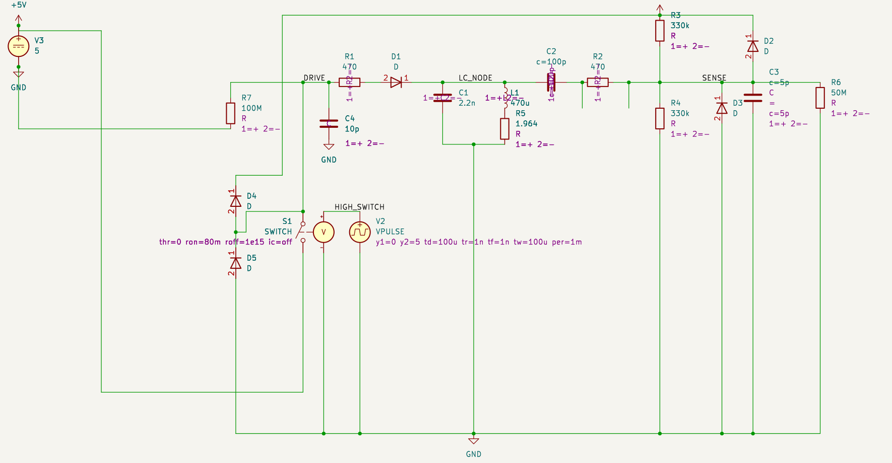
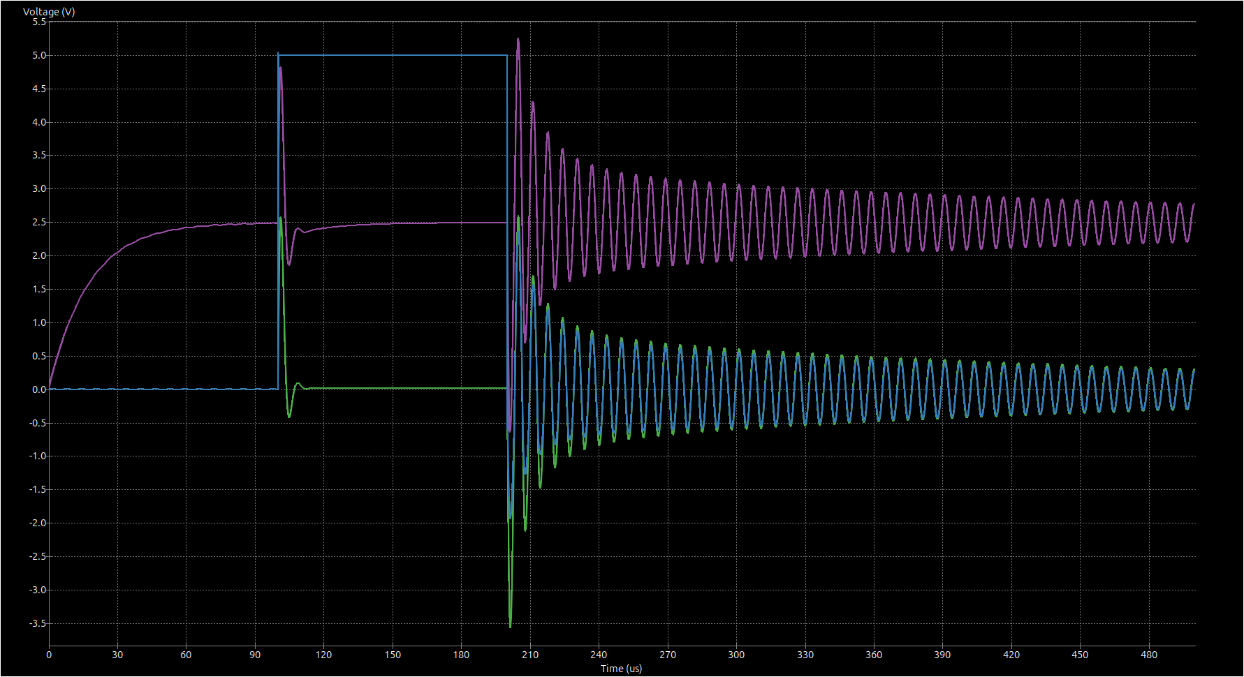
The simulation shows a clean ~156 kHz ring-down after the drive pulse ends at 200 µs. Blue is the drive, green the tank node and purple the biased sense node. Many cycles cross the comparator's 2.5 V threshold. The topology works, so the problem had to be physical.
Root cause: copper under the inductors. Rev1 had a solid GND pour on both layers directly beneath L1 and L2. The coils' open magnetic field induces eddy currents in that copper. Those currents load the tanks and destroy their Q. Rev2 adds copper-pour keepouts under and around both inductors and the sense circuitry, and uses 470 µH coils. On rev2 the tanks ring as expected.
Inspiration:
Helpful references:
firmware/) and CI: Apache-2.0.firmware/mcc_generated_files/ is generated by MPLAB Code Configurator and remains under
Microchip's license, which only allows its use with
Microchip products. The firmware images contain this code.Per-file details follow the REUSE specification (SPDX headers and
REUSE.toml); CI checks compliance with reuse lint.
This project has been prototyped at AISLER. You can instantly order as well by clicking on the badge at the top.
In case you want to build this (or any other project) at AISLER, here's a 10€ discount code:
MakeInEurope-ZDCTN
| Qty | Value | Footprint | References |
|---|---|---|---|
| 5 | 470 | Resistor_SMD:R_0603_1608Metric | R2, R6, R7, R10, R11 |
| 4 | 330k | Resistor_SMD:R_0603_1608Metric | R4, R5, R8, R9 |
| 3 | Fiducial | Fiducial:Fiducial_1mm_Mask3mm | FID1, FID2, FID3 |
| 3 | MountingHole | MountingHole:MountingHole_2.2mm_M2_ISO7380 | H1, H2, H3 |
| 2 | 0.1uF | Capacitor_SMD:C_0603_1608Metric | C1, C2 |
| 2 | 100pF | Capacitor_SMD:C_0603_1608Metric | C4, C5 |
| 2 | 2.2nF | Capacitor_SMD:C_0603_1608Metric | C6, C7 |
| 2 | 470uH | Inductor_Fastron_THT:L_Radial_D4.80mm_P2.50mm_Fastron_05HCP | L1, L2 |
| 2 | Conn_01x01 | TestPoint:TestPoint_Keystone_5000-5004_Miniature | J3, J4 |
| 2 | SS14 | Diode_SMD:D_SOD-123F | D2, D3 |
| 1 | 10k | Resistor_SMD:R_0603_1608Metric | R1 |
| 1 | 10uF | Capacitor_SMD:C_0603_1608Metric | C3 |
| 1 | 220 | Resistor_SMD:R_0805_2012Metric | R3 |
| 1 | B5819W | Diode_SMD:D_SOD-123 | D1 |
| 1 | Conn_01x04 | Connector_JST:JST_XH_S4B-XH-A_1x04_P2.50mm_Horizontal | J1 |
| 1 | Conn_PIC_ICSP_ICD | Connector_PinHeader_1.27mm:PinHeader_1x06_P1.27mm_Vertical | J2 |
| 1 | G*** | kibuzzard-6924F13D | kibuzzard-6924F13D |
| 1 | G*** | kibuzzard-69E7705E | kibuzzard-69E7705E |
| 1 | G*** | kibuzzard-69451647 | kibuzzard-69451647 |
| 1 | G*** | kibuzzard-69E7706B | kibuzzard-69E7706B |
| 1 | G*** | kibuzzard-6924F10E | kibuzzard-6924F10E |
| 1 | G*** | kibuzzard-69E77073 | kibuzzard-69E77073 |
| 1 | G*** | kibuzzard-6945164F | kibuzzard-6945164F |
| 1 | G*** | kibuzzard-69E77065 | kibuzzard-69E77065 |
| 1 | G*** | kibuzzard-6924F128 | kibuzzard-6924F128 |
| 1 | HCPL-817-30DE | Package_SO:SSO-4_6.7x5.1mm_P2.54mm_Clearance8mm | U2 |
| 1 | KiCad-Logo2_6mm_SilkScreen | Symbol:KiCad-Logo2_6mm_SilkScreen | LOGO2 |
| 1 | OSHW-Symbol_6.7x6mm_SilkScreen | Symbol:OSHW-Symbol_6.7x6mm_SilkScreen | LOGO1 |
| 1 | PIC18F25K80_IML | Package_DFN_QFN:QFN-28-1EP_6x6mm_P0.65mm_EP4.25x4.25mm | U1 |
MF-Room/mseq_pcb
KiCad 10 hardware design for MSeq embedded, the microcontroller implementation of the MSeq MIDI sequencer.


PoJD/kicad
Printed circuit boards. A container for all projects, successor to the older eagle repo.


emiz-jh/2526_Maker_ClawMachine
Projet de machine à pince réalisé dans le cadre de l'Option Maker ENSEA 2025-2026.


USA-RedDragon/SnekSafe
Keep your snek safe by controlling temperature and lighting.

It measures 62 × 38.1 mm and has 2 copper layers, 1.58 mm thick.
46 parts, built around the PIC18F25K80-I/MM, HCPL-817-30DE, 06035C104JAT2A and SS14MH. The full list of its parts is on this page, with links to each part's symbol and footprint where PCBKit's library has them.
From the usimd/water-meter-counter repository on GitHub, at the commit this page was made from: the board is water-meter-counter.kicad_pcb and its schematic water-meter-counter.kicad_sch. PCBKit opens the board in the browser, with nothing to install.
Its repository states no licence, so its author keeps all rights: ask usimd before reusing the design.