4 layers57.4 × 23.9 mm
 uinika/UINIO-USB-Serial2
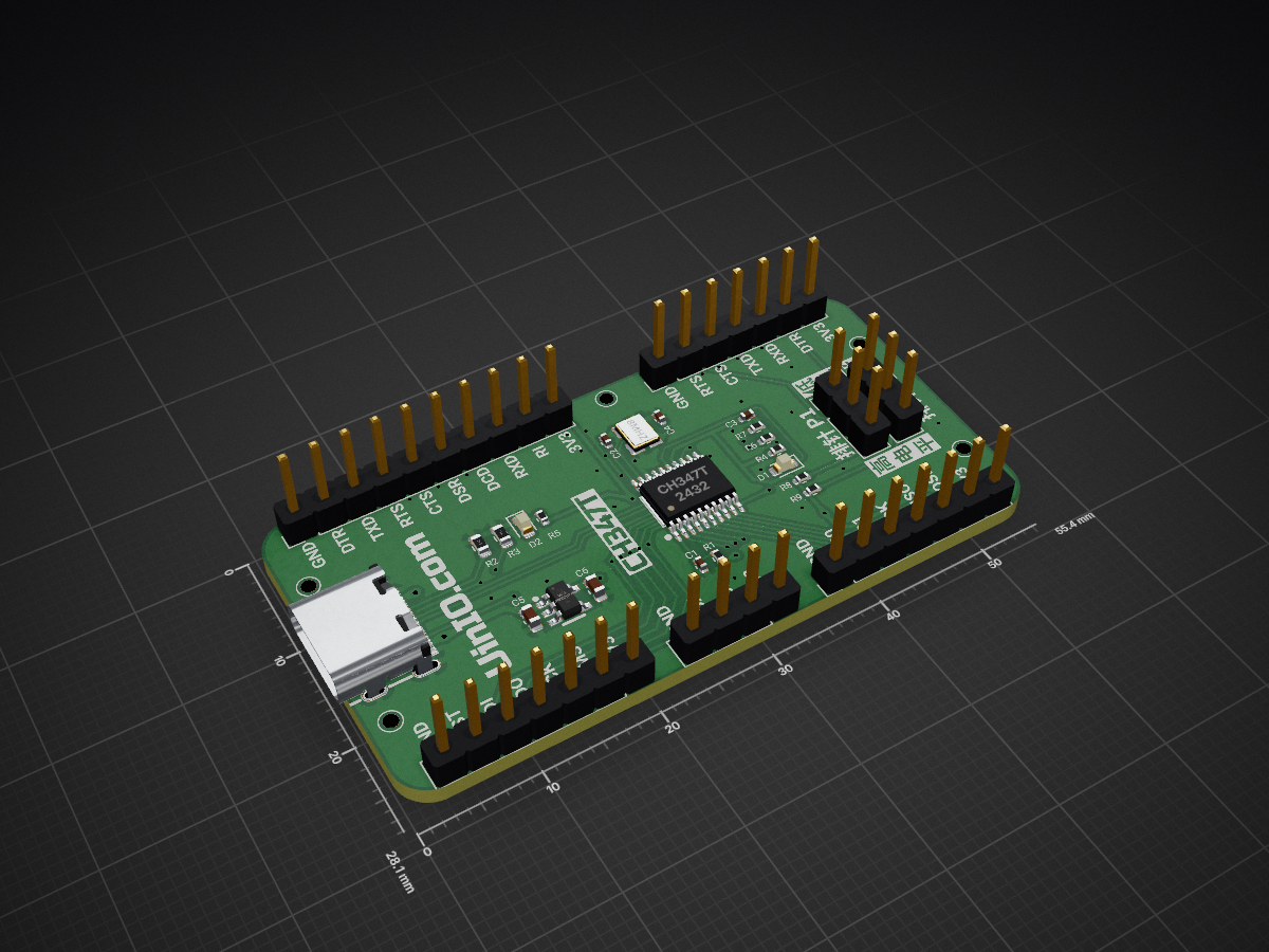
A Serial Protocol Converter base on CH347T related I2C & SPI and so on.
UINIO USB Serial is an open-source printed circuit board by uinika, from the uinika/UINIO-USB-Serial repository on GitHub. It is a 2-layer board of 55.3 × 28.1 mm with 33 parts on 32 nets, routed with 262 tracks and 65 vias.
It is built around the CH347T and ME6211C33M5G-N. Its parts include 9 resistors, 7 connectors, 6 capacitors, 2 ICs and 2 diodes. It belongs with the interfaces and adapters boards of this library.


UINIO-USB-Serial 是一款基于沁恒高速 USB 2.0 转接芯片 CH347T 的 USB 串行协议转换工具,支持 USB 接口转 GPIO、UART、I²C、SPI、JTAG, 可以用于调试 3.3V 电平的微控制器与外设的通信,也可以配合使用 UINIO-Signal-Translator 完成 3.3V 到 1.8V 的高速信号转换,从而实现对 FPGA 芯片的调试与下载。
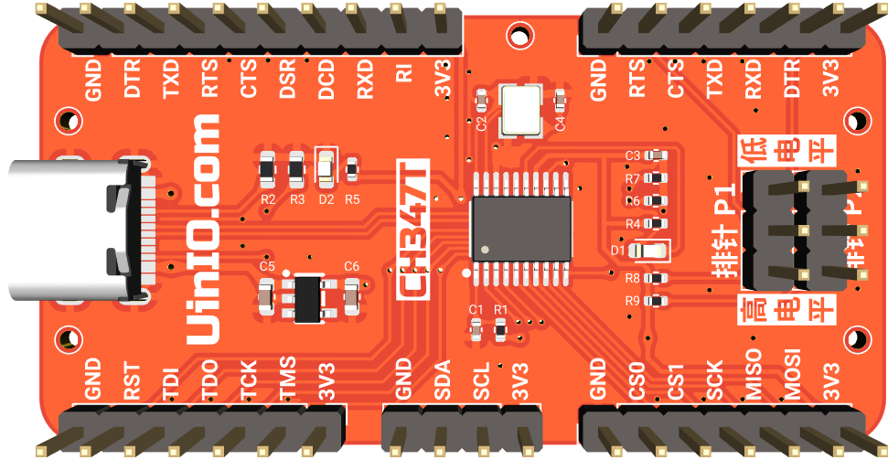
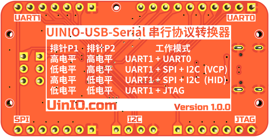
TSSOP20 封装;P1 与 P2 排针的跳线帽进行配置;1mm 直径固定螺丝孔,方便与外壳进行固定组装;1.8V;UINIO-USB-Serial 可以支持下面的四种工作模式:
9Mbps。36MHz,并且支持 2 路片选信号线,可以分时操作两个 SPI 从设备。18Mbit/s。这些模式分别由 CH347T 的 DTR1 和 RTS1 引脚的电平状态进行控制:
| 排针 P1 | 排针 P2 | 工作模式 |
|---|---|---|
低电平 | 低电平 | UART1 + JTAG |
高电平 | 高电平 | UART1 + UART0 |
高电平 | 低电平 | UART1 + SPI + I2C (HID) |
低电平 | 高电平 | UART1 + SPI + I2C (VCP) |
UinIO.com 电子技术实验室 为 UINIO-USB-Serial 开源项目提供了如下一系列技术参考资料:
| Qty | Value | Footprint | References |
|---|---|---|---|
| 5 | 4.7K | Resistor_SMD:R_0402_1005Metric | R1, R6, R7, R8, R9 |
| 5 | Hole-1mm | Uinio:Hole-1mm | HOLE**, HOLE**, HOLE**, HOLE**, HOLE** |
| 3 | Conn_01x07_Pin | Connector_PinHeader_2.54mm:PinHeader_1x07_P2.54mm_Vertical | J1, J4, J7 |
| 2 | 0.1uF | Capacitor_SMD:C_0402_1005Metric | C1, C3 |
| 2 | 1uF | Capacitor_SMD:C_0603_1608Metric | C5, C6 |
| 2 | 20pF | Capacitor_SMD:C_0402_1005Metric | C2, C4 |
| 2 | 2K | Resistor_SMD:R_0402_1005Metric | R4, R5 |
| 2 | 5.1K | Resistor_SMD:R_0603_1608Metric | R2, R3 |
| 1 | 8MHz | Crystal:Crystal_SMD_3225-4Pin_3.2x2.5mm | Y1 |
| 1 | CH347T | Uinio:TSSOP-20_L6.5-W4.4-P0.65-LS6.4-BL | U1 |
| 1 | Conn_01x04_Pin | Connector_PinHeader_2.54mm:PinHeader_1x04_P2.54mm_Vertical | J3 |
| 1 | Conn_01x10_Pin | Connector_PinHeader_2.54mm:PinHeader_1x10_P2.54mm_Vertical | J2 |
| 1 | LED Blue | LED_SMD:LED_0603_1608Metric | D1 |
| 1 | LED_Red | LED_SMD:LED_0603_1608Metric | D2 |
| 1 | ME6211C33M5G | Uinio:SOT-23-5_L3.0-W1.7-P0.95-LS2.8-BR | U2 |
| 1 | USB_Type_C_16Pin | Uinio:USB-C-SMD_TYPEC-304J-BCP16 | USB1 |
| 1 | 排针P1 | Connector_PinHeader_2.54mm:PinHeader_1x03_P2.54mm_Vertical | J5 |
| 1 | 排针P2 | Connector_PinHeader_2.54mm:PinHeader_1x03_P2.54mm_Vertical | J6 |
It measures 55.3 × 28.1 mm and has 2 copper layers, 1.6 mm thick.
33 parts, built around the CH347T and ME6211C33M5G-N. The full list of its parts is on this page, with links to each part's symbol and footprint where PCBKit's library has them.
From the uinika/UINIO-USB-Serial repository on GitHub, at the commit this page was made from: the board is UINIO-USB-Serial.kicad_pcb and its schematic UINIO-USB-Serial.kicad_sch. PCBKit opens the board in the browser, with nothing to install.
Its repository states no licence, so its author keeps all rights: ask uinika before reusing the design.


CYP4502D6/DCJ11CoreBoard
PDP-11 replica project based on the DEC DCJ-11 chipset, utilizing FPGA as bus controller and peripheral emulator, using external SRAM to provide system memory


FreeYourStream/freedeck-hardware
all the stuff you need to build your own FreeDeck