4 layers100 × 61 mm
No fly zone remote revised
tynix5/no_fly_zone
STM32-based quadcopter and remote controller running on custom hardware and software
68 parts1

 tynix5/no_fly_zone1
STM32-based quadcopter and remote controller running on custom hardware and software
No fly zone is an open-source printed circuit board by tynix5, from the tynix5/no_fly_zone repository on GitHub. It is a 4-layer board of 108.4 × 50 mm with 90 parts on 123 nets, routed with 654 tracks and 163 vias.
It is built around the NRF24L01P-R, LPS25HB and AP2112K-3.3, with the LSM6DS3TR-C and MPZ2012S601AT000 among its other parts. Its parts include 31 capacitors, 15 connectors, 13 resistors, 9 ICs and 5 diodes. It belongs with the robots and motor control boards and the STM32 boards of this library.


A custom designed quadcopter and remote combination featuring a custom STM32-based flight controller PCB and STM32-based remote control PCB that combine aspects of sensor fusion, quaternion-based attitude control, wireless communication, and digital ESC communication.
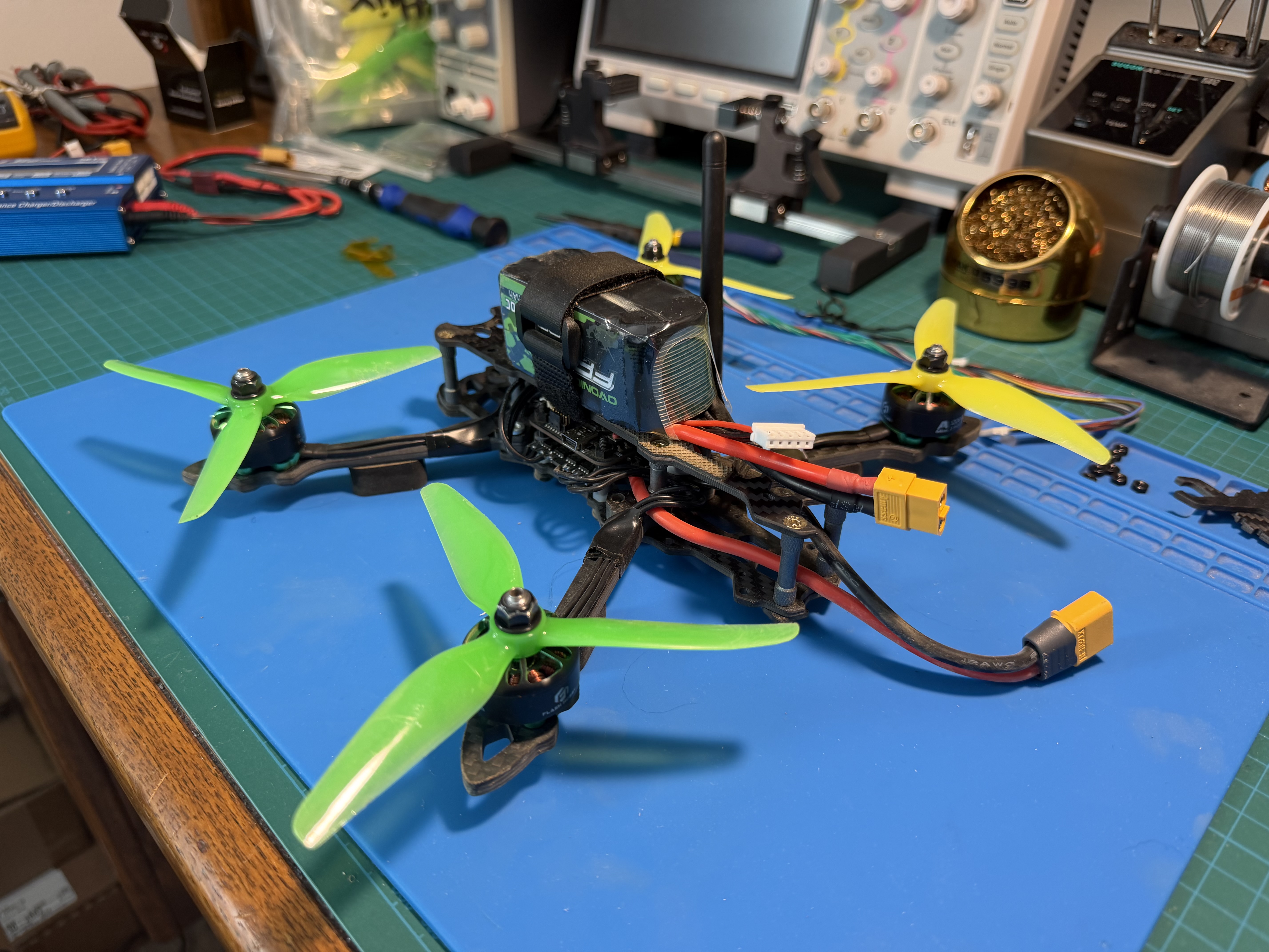
Fully-assembled quadcopter
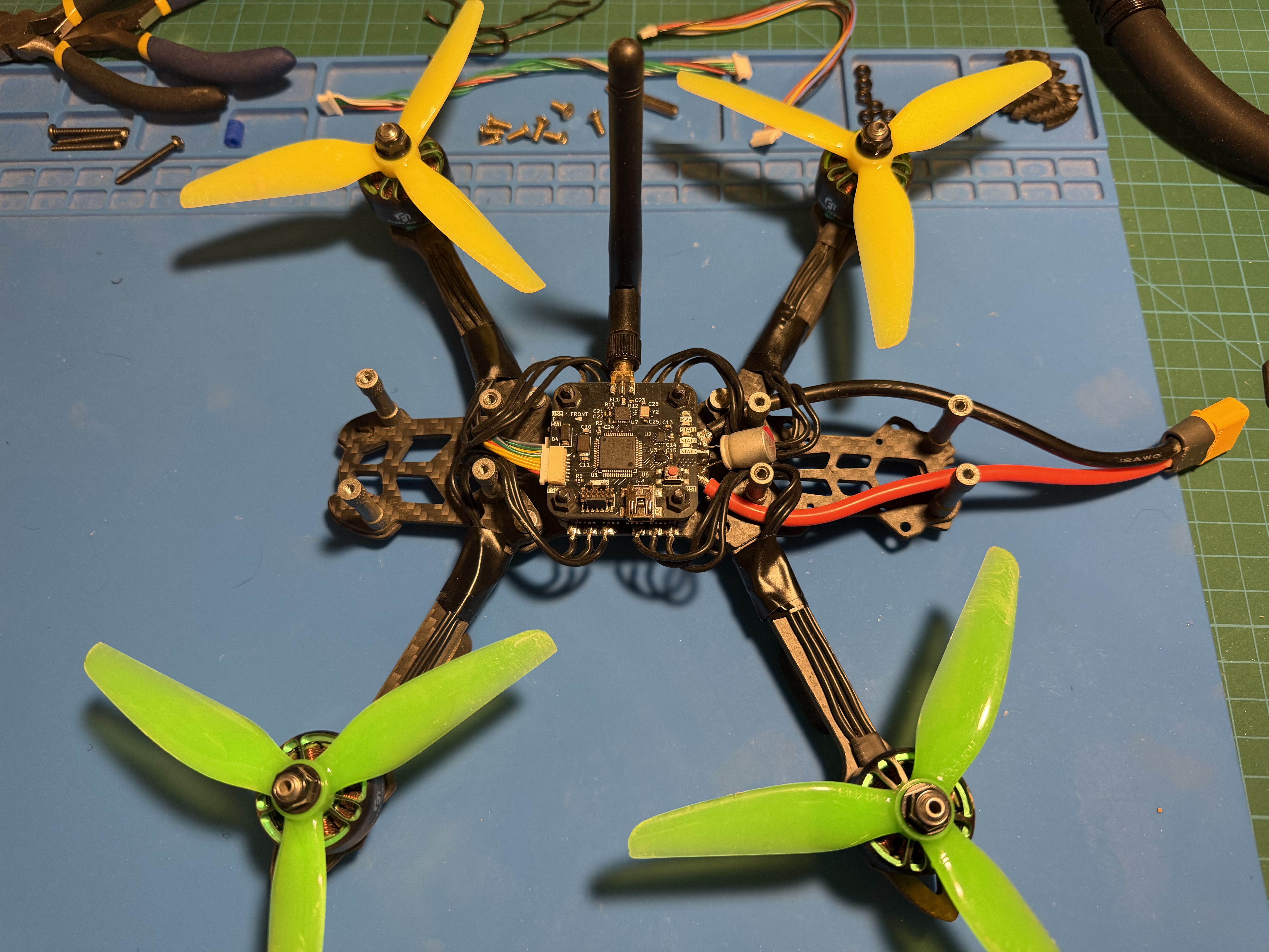
Flight controller pictured with ESC mounted underneath
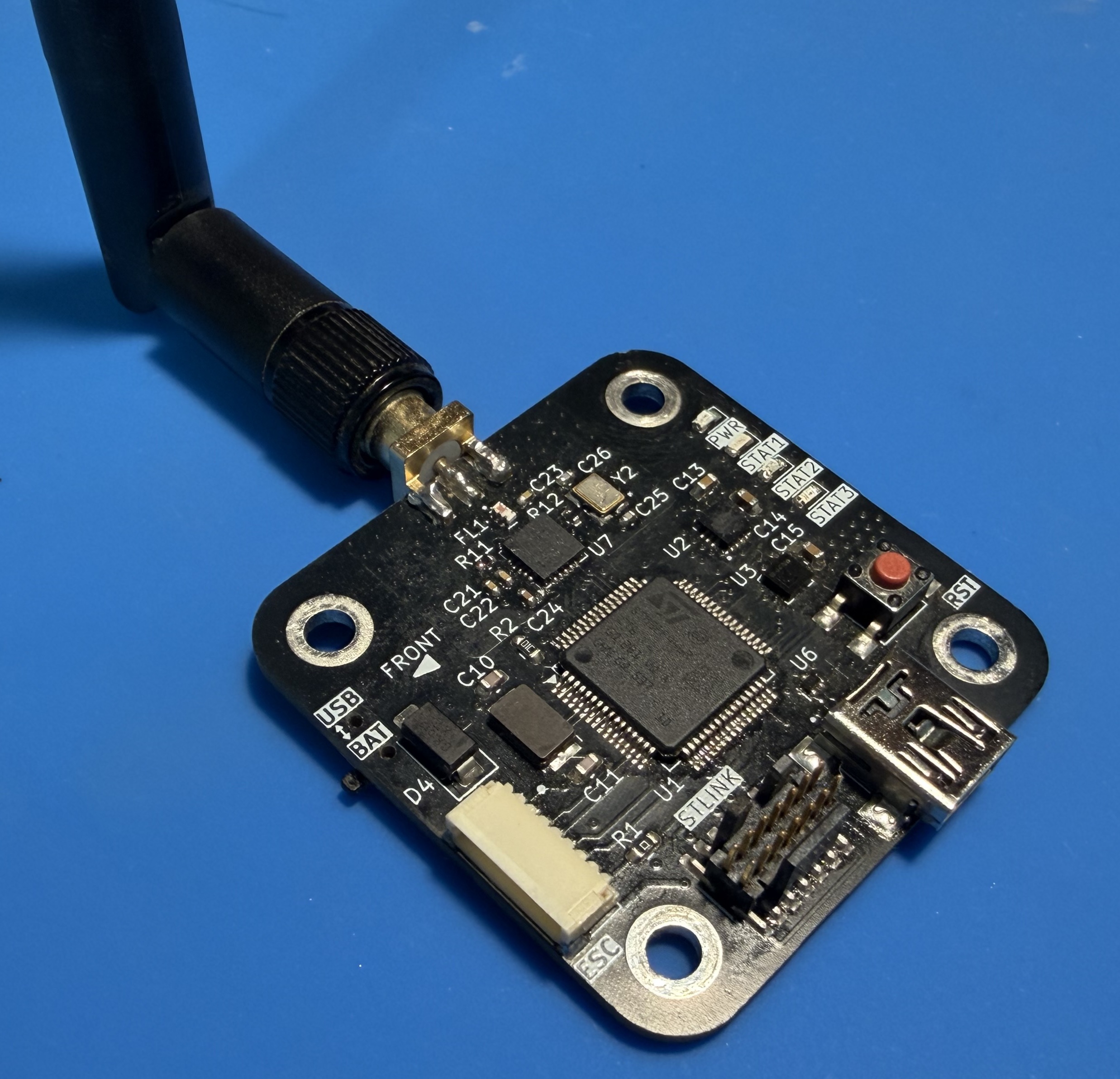
Custom flight controller PCB
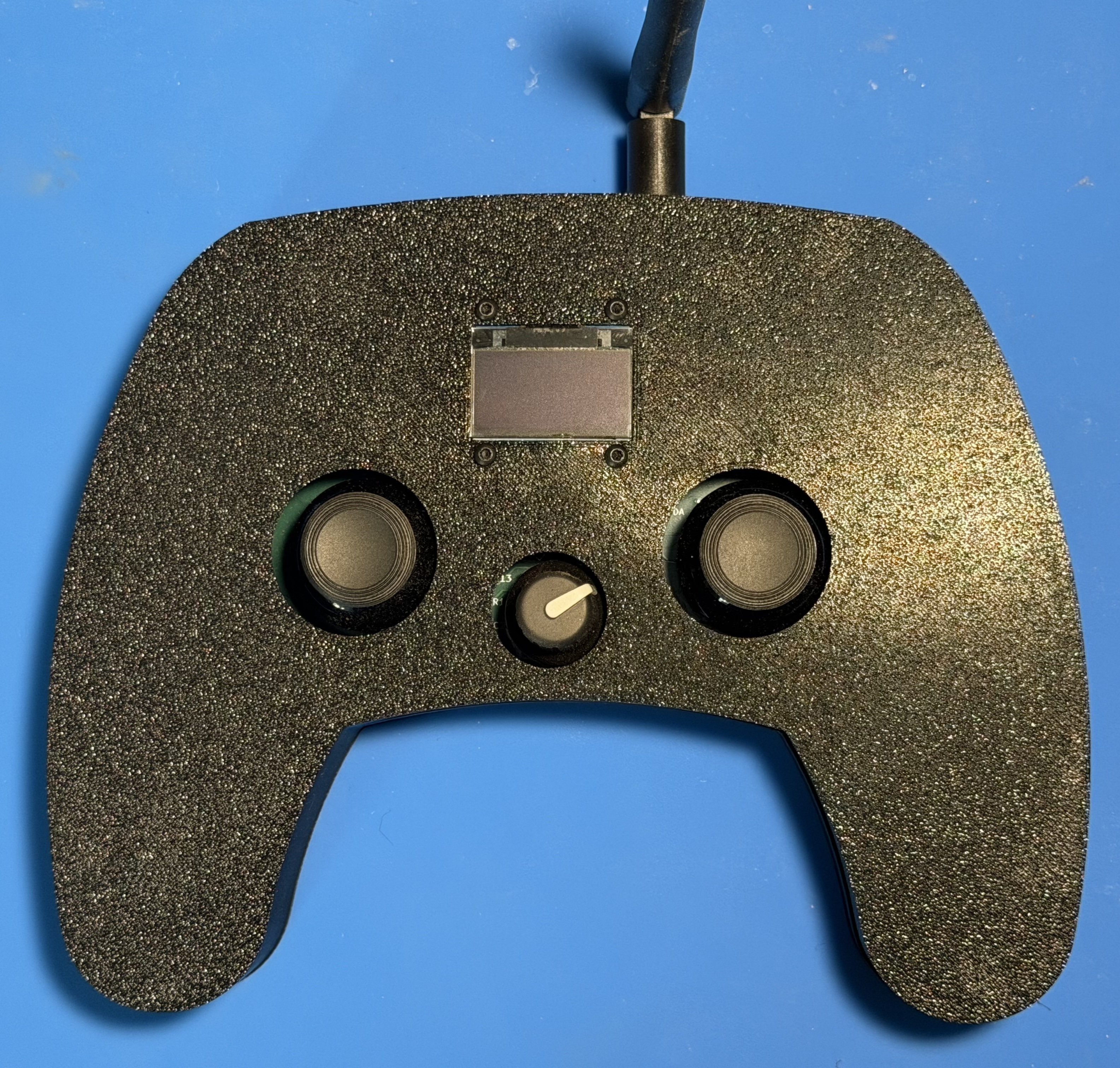
Custom remote control frame
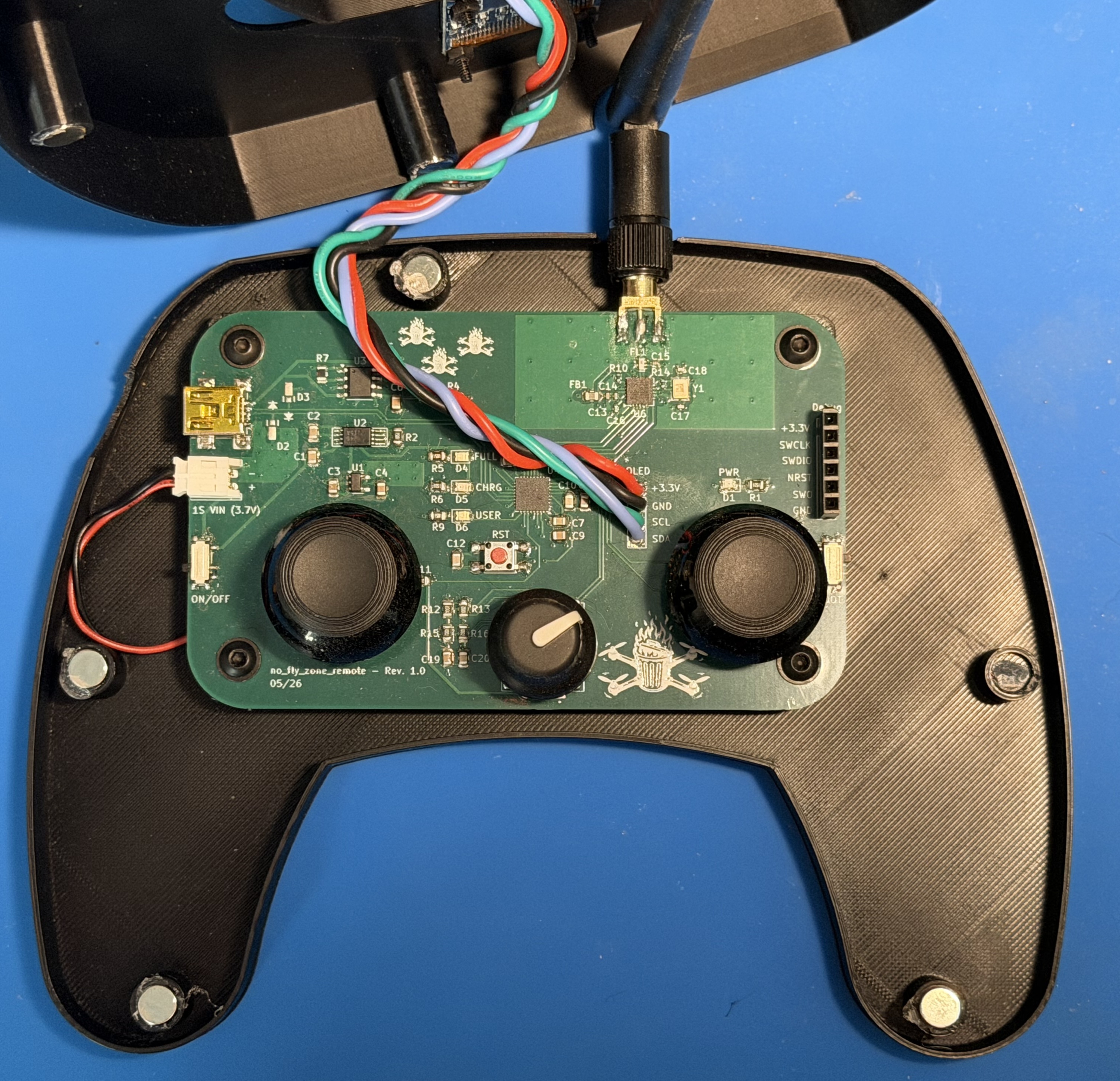
Remote control PCB
This project focused on the design and implementation of a custom quadcopter flight controller paired with a complementary custom remote from the ground-up. Rather than buying an off-the-shelf flight controller and remote, almost all aspects of both the flight controller and remote were custom made. I decided to do this project because I have always been fascinated by drones, and I liked the challenge it would bring. It ties together all aspects of signal integrity, systems, low-level firmware, and digital signal processing. Below is a summary of some of the aspects this project entailed...
No off-the-shelf software or firmware was used, but some aspects of flight controller design were inspired by PixHawk and Betaflight. Components purchased off-shelf include the ESC, four BLDC motors, quadcopter frame, and board components.
Contains source code, build settings, documentation, and additional information/diagrams for both the remote and quadcopter. A link to the STM32 submodule library can also be found, where most of the sensor implementation is found.
Note: The scripts subfolder in /firmware contains AI-generated Python scripts for validation and testing purposes. AI was NOT used to generate code found on either the remote or flight controller.
Contains KiCAD schematics and and PCB fabrication outputs for both the remote and quadcopter. Additional information on hardware selection and design can be found in each respective subfolder.
Contains the 3D files for the spacers used to separate the STM32 flight controller board and ESC board, along with the 3D files for the remote control housing.
Contains relevant screenshots for those in other READMEs
All components purchased off-shelf can be found in the bom.txt file, and the BOMs for the PCBs can be found in the .csv files in their respective folders.
| Qty | Value | Footprint | References |
|---|---|---|---|
| 13 | 100n | Capacitor_SMD:C_0805_2012Metric | C1, C2, C3, C4, C5, C7, C9, C14, C16, C18, C19, C20, C23 |
| 8 | M3 | MountingHole:MountingHole_3.2mm_M3_DIN965_Pad | H1, H2, H3, H4, H5, H6, H7, H8 |
| 5 | 1k5 | Resistor_SMD:R_0805_2012Metric | R2, R3, R4, R6, R7 |
| 3 | 10u | Capacitor_SMD:C_0805_2012Metric | C6, C13, C15 |
| 3 | 1u | Capacitor_SMD:C_0805_2012Metric | C8, C21, C22 |
| 2 | 1k | Resistor_SMD:R_0805_2012Metric | R5, R11 |
| 2 | 22p | Capacitor_SMD:C_0402_1005Metric | C30, C31 |
| 2 | 22p | Capacitor_SMD:C_0805_2012Metric | C10, C11 |
| 2 | PWR | Connector_JST:JST_SH_SM02B-SRSS-TB_1x02-1MP_P1.00mm_Horizontal | J3, J4 |
| 1 | 10k | Resistor_SMD:R_0805_2012Metric | R1 |
| 1 | 10n | Capacitor_SMD:C_0402_1005Metric | C26 |
| 1 | 15u | Inductor_SMD:L_0805_2012Metric | L2 |
| 1 | 16MHz | custom_footprints:XTAL_ABM8AIG-16.000MHZ-12-2Z-T3 | Y2 |
| 1 | 1M | Resistor_SMD:R_0402_1005Metric | R13 |
| 1 | 1n | Capacitor_SMD:C_0402_1005Metric | C27 |
| 1 | 220n | Capacitor_SMD:C_0805_2012Metric | C17 |
| 1 | 22k | Resistor_SMD:R_0402_1005Metric | R12 |
| 1 | 22k1 | Resistor_SMD:R_0805_2012Metric | R9 |
| 1 | 22u | Capacitor_SMD:C_0805_2012Metric | C25 |
| 1 | 2450BM14A0002T | custom_footprints:FIL_2450BM14A0002T | FL1 |
| 1 | 2n2 | Capacitor_SMD:C_0402_1005Metric | C28 |
| 1 | 2u2 | Capacitor_SMD:C_0805_2012Metric | C24 |
| 1 | 33n | Capacitor_SMD:C_0402_1005Metric | C29 |
| 1 | 47n | Inductor_SMD:L_0805_2012Metric | L1 |
| 1 | 4u7 | Capacitor_SMD:C_0805_2012Metric | C12 |
| 1 | 5k | Resistor_SMD:R_0805_2012Metric | R10 |
| 1 | 88k7 | Resistor_SMD:R_0805_2012Metric | R8 |
| 1 | 8MHz | custom_footprints:XTAL_ABM3-16.000MHZ-D2Y-T | Y1 |
| 1 | AP2112K-3.3 | Package_TO_SOT_SMD:SOT-23-5 | U6 |
| 1 | ATGM336H | custom_footprints:ATGM336H | U3 |
| 1 | BAR | Connector_JST:JST_SH_SM05B-SRSS-TB_1x05-1MP_P1.00mm_Horizontal | J7 |
| 1 | BOOT0 | Button_Switch_SMD:SW_SPDT_PCM12 | SW2 |
| 1 | CON-SMA-EDGE-S | custom_footprints:RFSOLUTIONS_CON-SMA-EDGE-S | J15 |
| 1 | Debug | Connector_PinHeader_2.54mm:PinHeader_2x03_P2.54mm_Vertical | J2 |
| 1 | ESC | Connector_JST:JST_SH_SM08B-SRSS-TB_1x08-1MP_P1.00mm_Horizontal | J1 |
| 1 | GPS | Connector_JST:JST_SH_SM03B-SRSS-TB_1x03-1MP_P1.00mm_Horizontal | J11 |
| 1 | IIS2MDCTR | custom_footprints:IIS2MDCTR | U2 |
| 1 | IMU | Connector_JST:JST_SH_SM06B-SRSS-TB_1x06-1MP_P1.00mm_Horizontal | J5 |
| 1 | LMR50410 | Package_TO_SOT_SMD:SOT-23-6 | U7 |
| 1 | LPS25HB | Package_LGA:ST_HLGA-10_2.5x2.5mm_P0.6mm_LayoutBorder3x2y | U5 |
| 1 | LSM6DS3TR-C | custom_footprints:LSM6DS3TR | U4 |
| 1 | MAG | Connector_JST:JST_SH_SM04B-SRSS-TB_1x04-1MP_P1.00mm_Horizontal | J9 |
| 1 | MPZ2012S601AT000 | Resistor_SMD:R_0805_2012Metric | FB1 |
| 1 | NRST | Button_Switch_SMD:SW_SPST_TL3305A | SW1 |
| 1 | PWR | LED_SMD:LED_0805_2012Metric | D4 |
| 1 | RED | LED_SMD:LED_0805_2012Metric | D5 |
| 1 | SPI1_BAR | Connector_JST:JST_SH_SM05B-SRSS-TB_1x05-1MP_P1.00mm_Horizontal | J8 |
| 1 | SPI1_IMU | Connector_JST:JST_SH_SM06B-SRSS-TB_1x06-1MP_P1.00mm_Horizontal | J6 |
| 1 | SPI2 | Connector_JST:JST_SH_SM04B-SRSS-TB_1x04-1MP_P1.00mm_Horizontal | J10 |
| 1 | STAT1 | LED_SMD:LED_0805_2012Metric | D2 |
| 1 | STAT2 | LED_SMD:LED_0805_2012Metric | D3 |
| 1 | STM32F446RCTx | Package_QFP:LQFP-64_10x10mm_P0.5mm | U1 |
| 1 | U.FL_R_SMT | custom_footprints:HRS_UFL_R_SMT | J13 |
| 1 | UART1 | Connector_JST:JST_SH_SM03B-SRSS-TB_1x03-1MP_P1.00mm_Horizontal | J12 |
| 1 | USB_B_Mini | custom_footprints:EDAC_690-005-299-043 | J14 |
| 1 | USER | LED_SMD:LED_0805_2012Metric | D1 |
| 1 | VSEL | Button_Switch_SMD:SW_SPDT_PCM12 | SW3 |
| 1 | nRF24L01P | Package_DFN_QFN:QFN-20-1EP_4x4mm_P0.5mm_EP2.5x2.5mm | U9 |
| 1 | ~ | Package_TO_SOT_SMD:SOT-723 | U8 |
tynix5/no_fly_zone
STM32-based quadcopter and remote controller running on custom hardware and software

tynix5/no_fly_zone
STM32-based quadcopter and remote controller running on custom hardware and software

tynix5/no_fly_zone
STM32-based quadcopter and remote controller running on custom hardware and software

tynix5/no_fly_zone
STM32-based quadcopter and remote controller running on custom hardware and software

tynix5/no_fly_zone
STM32-based quadcopter and remote controller running on custom hardware and software

souptik-samanta/Sensor-Node
A compact environmental monitoring node built around the STM32L052 microcontroller. The board measures temperature, humidity, while providing onboard storage and support for external SX1262 LoRa modules.

dhruxraj/stm32-can-ecu
A compact, "ECU-style" CAN node for learning and prototyping automotive-type embedded software. It has an STM32G4 MCU, a CAN transceiver with protection and switchable termination, a 6-axis IMU, a protected 8-18 V…


Parwaz-Dynamics/Embedded-In-Bones
My personal embedded systems learning journey projects.

vbartusevicius/weather-station
Open-source rooftop weather and air-quality station with no moving parts (Ø 96 × 235 mm, UV-stabilised ASA): ultrasonic wind, acoustic rain and hail, UV / sunlight / night-sky brightness, temperature, humidity…

aitesam961/OpenADSP
An Embedded Digital Signal Processing Device for Audio signals.

yedidiaSch/FalconDrone
[IN PROGRESS] High-performance flight controller for quadcopters, providing real-time stabilization and attitude control using FreeRTOS and C++ on STM32

Reid-n0rc/LMS-6_Interface_Board
Interface to the LMS-6 radiosonde carde edge connector.
It measures 108.4 × 50 mm and has 4 copper layers, 1.61 mm thick.
90 parts, built around the NRF24L01P-R, LPS25HB, AP2112K-3.3 and LSM6DS3TR-C. The full list of its parts is on this page, with links to each part's symbol and footprint where PCBKit's library has them.
From the tynix5/no_fly_zone repository on GitHub, at the commit this page was made from: the board is hardware/no_fly_zone/rev1.0/no_fly_zone.kicad_pcb and its schematic hardware/no_fly_zone/rev1.0/mcu.kicad_sch. PCBKit opens the board in the browser, with nothing to install.
Its repository states no licence, so its author keeps all rights: ask tynix5 before reusing the design.