2 layers
Full Circuit
EthanSousaProjects/CBR_Custom_Cluster
A custom cluster design for my CBR 125RW6 (2006 carb model) to replace the old large mechanical cluster with a smaller simpler design.
76 partsGPL-3.0

 Reid-n0rc/LMS-6_Interface_Board4
Interface to the LMS-6 radiosonde carde edge connector.
Programmer Board is an open-source printed circuit board by Reid-n0rc, from the Reid-n0rc/LMS-6_Interface_Board repository on GitHub, published under the GPL-3.0 licence. It is a 2-layer board of 80 × 96 mm with 55 parts on 73 nets, routed with 438 tracks and 29 vias.
It is built around the TEC 2-1219WI, FT232RL-REEL and MPZ2012S601AT000, with the UJ2-MIBH-4-SMT-TR, 302-S101 and EBC20DRAS among its other parts. Its parts include 11 connectors, 10 resistors, 8 capacitors, 6 diodes and 4 fuses. It belongs with the interfaces and adapters boards of this library.


Interface to the LMS-6 radiosonde carde edge connector.
This project provides an easy way to connect to the UARTs, in circuit programming of the ST7, and provide power to the LMS6 Radiosonde using a card edge connector.
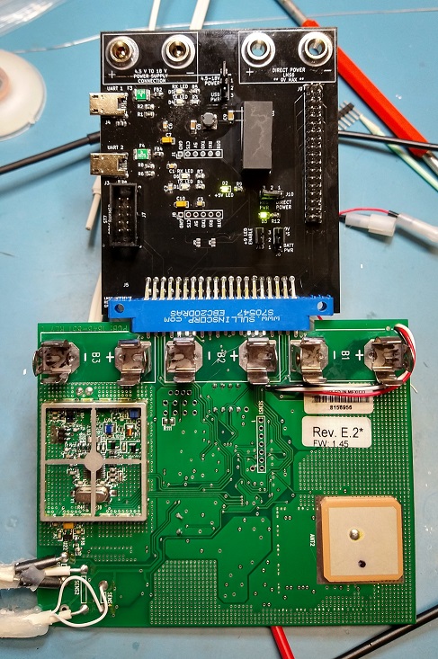
File for fabrication are in (./Fabrication) directory. This contains the gerber files and BOM
Depending on how you intend on using this board, many of the parts can be omitted. The minimal build provides a connection for the ST7 programmer and card edge interface. The LMS6 will be powered by the CR123 batteries installed on the LMS6. This configuration requires J5, J6, J7, and one shunt connector (jumper).
J6 has pins 1 and 2 jumpered together to connect the battery power. The shunt connector will allow the LMS6 to be turned on and off.
JP3 needs cut and the alternate postion soldered to receive data from the debugging port. Debugging seial is 8N1 at 500kbits/sec.
| Qty | Value | Footprint | References |
|---|---|---|---|
| 6 | LG R971-KN-1 | LED_SMD:LED_0805_2012Metric_Pad1.15x1.40mm_HandSolder | D1, D2, D3, D4, D5, D6 |
| 5 | 280 | Resistor_SMD:R_0805_2012Metric_Pad1.20x1.40mm_HandSolder | R3, R4, R5, R7, R9 |
| 4 | 0.1uF | Capacitor_SMD:C_0805_2012Metric_Pad1.18x1.45mm_HandSolder | C1, C2, C3, C6 |
| 4 | 27 | Resistor_SMD:R_0805_2012Metric_Pad1.20x1.40mm_HandSolder | R1, R2, R6, R8 |
| 4 | 575-4 | LMS-6_Interface_Board:575_Banana_Jack | E1, E2, E3, E4 |
| 4 | MPZ2012S601AT000 | digikey-footprints:0805 | FB1, FB2, FB3, FB4 |
| 3 | Conn_01x03 | Connector_PinHeader_2.54mm:PinHeader_1x03_P2.54mm_Vertical | J2, J6, J10 |
| 3 | JUMPER-SMT_3_1-NC | Jumpers:SMT-JUMPER_3_1-NC_TRACE_NO-SILK | JP1, JP2, JP3 |
| 2 | 10uF | Capacitor_Tantalum_SMD:CP_EIA-3216-10_Kemet-I_Pad1.58x1.35mm_HandSolder | C7, C10 |
| 2 | 750 mA | Resistor_SMD:R_1812_4532Metric_Pad1.30x3.40mm_HandSolder | F3, F4 |
| 2 | 750mA | Resistor_SMD:R_1812_4532Metric_Pad1.30x3.40mm_HandSolder | F1, F2 |
| 2 | Conn_01x06 | Connector_PinHeader_2.54mm:PinHeader_1x06_P2.54mm_Vertical | J1, J8 |
| 2 | FT232RL-REEL | digikey-footprints:SSOP-28_W5.30mm | U1, U3 |
| 2 | UJ2-MIBH-4-SMT-TR | digikey-footprints:USB_Micro_B_Male_UJ2-MIBH-4-SMT-TR | J3, J4 |
| 1 | 10uF | Capacitor_SMD:C_1206_3216Metric_Pad1.33x1.80mm_HandSolder | C8 |
| 1 | 302-S101 | digikey-footprints:PinHeader_2x5_P2.54mm_Drill1.02mm | J7 |
| 1 | 4.7uF | Capacitor_SMD:C_1206_3216Metric_Pad1.33x1.80mm_HandSolder | C9 |
| 1 | 909 | Resistor_SMD:R_0805_2012Metric_Pad1.20x1.40mm_HandSolder | R12 |
| 1 | Conn_01x02 | Connector_PinHeader_2.54mm:PinHeader_1x02_P2.54mm_Vertical | J13 |
| 1 | Conn_02x18_Odd_Even | Connector_PinHeader_2.54mm:PinHeader_2x18_P2.54mm_Vertical | J9 |
| 1 | EBC20DRAS | LMS-6_Interface_Board:EBC20DRAS | J5 |
| 1 | LOGO | LMS-6_Interface_Board:faceoff_med | G*** |
| 1 | TCK-154 | SamacSys_Parts:TCK154 | L1 |
| 1 | TEC2-1219WI | Converter_DCDC:Converter_DCDC_TRACO_TMR-xxxx_THT | U2 |
EthanSousaProjects/CBR_Custom_Cluster
A custom cluster design for my CBR 125RW6 (2006 carb model) to replace the old large mechanical cluster with a smaller simpler design.

nicolaeandreivasile/bike-embedded-app
Embedded application for bikes that collect and display various riding data.


jamesfletcher22/FreqSynthPCB
A PCB Design for an Si5351A Frequency Synthesiser with Manual Control


zenitheesc/Alcantara
Mobile Ground Station for stratospheric probe monitoring and rescue. Goes well with the Zenith Monitor app.


harp-tech/device.stepperdriver
A stepper motor controller device for four motors including individual quadrature encoders.
It measures 80 × 96 mm and has 2 copper layers, 0.8 mm thick.
55 parts, built around the TEC 2-1219WI, FT232RL-REEL, MPZ2012S601AT000 and UJ2-MIBH-4-SMT-TR. The full list of its parts is on this page, with links to each part's symbol and footprint where PCBKit's library has them.
From the Reid-n0rc/LMS-6_Interface_Board repository on GitHub, at the commit this page was made from: the board is KiCad Files/Programmer Board.kicad_pcb. PCBKit opens the board in the browser, with nothing to install.
Its repository publishes it under the GPL-3.0 licence: you may reuse it on that licence's terms (keep the author's notice, and for a copyleft licence share your changes alike).