4 layers50 × 65 mm
Multi Ferro DAQ
TUDA-MUST/Multi-Ferro-DAQ
Measurement Setup to analyze multiple ferroelectric sensors simultaneously
149 parts

 TUDA-MUST/ChrisBox6
4 Channel Charge Amplifier PCB
ChrisPCB is an open-source printed circuit board by TUDA-MUST, from the TUDA-MUST/ChrisBox repository on GitHub. It is a 4-layer board of 78 × 46.3 mm with 197 parts on 142 nets, routed with 1,229 tracks and 172 vias.
It is built around the AD8605ARTZ-R2, ESP32-S3-MINI-1-N8 and LM2775DSG, with the AP2112K-3.3, TP4056 and TPS73616DBV among its other parts. Its parts include 81 capacitors, 49 resistors, 16 ICs, 10 connectors and 9 diodes. It belongs with the ESP32 boards of this library.


Welcome to the PCB folder of ChrisBox! The ChrisBox PCB is designed with KiCad. The Project files and generated Exports are found here.
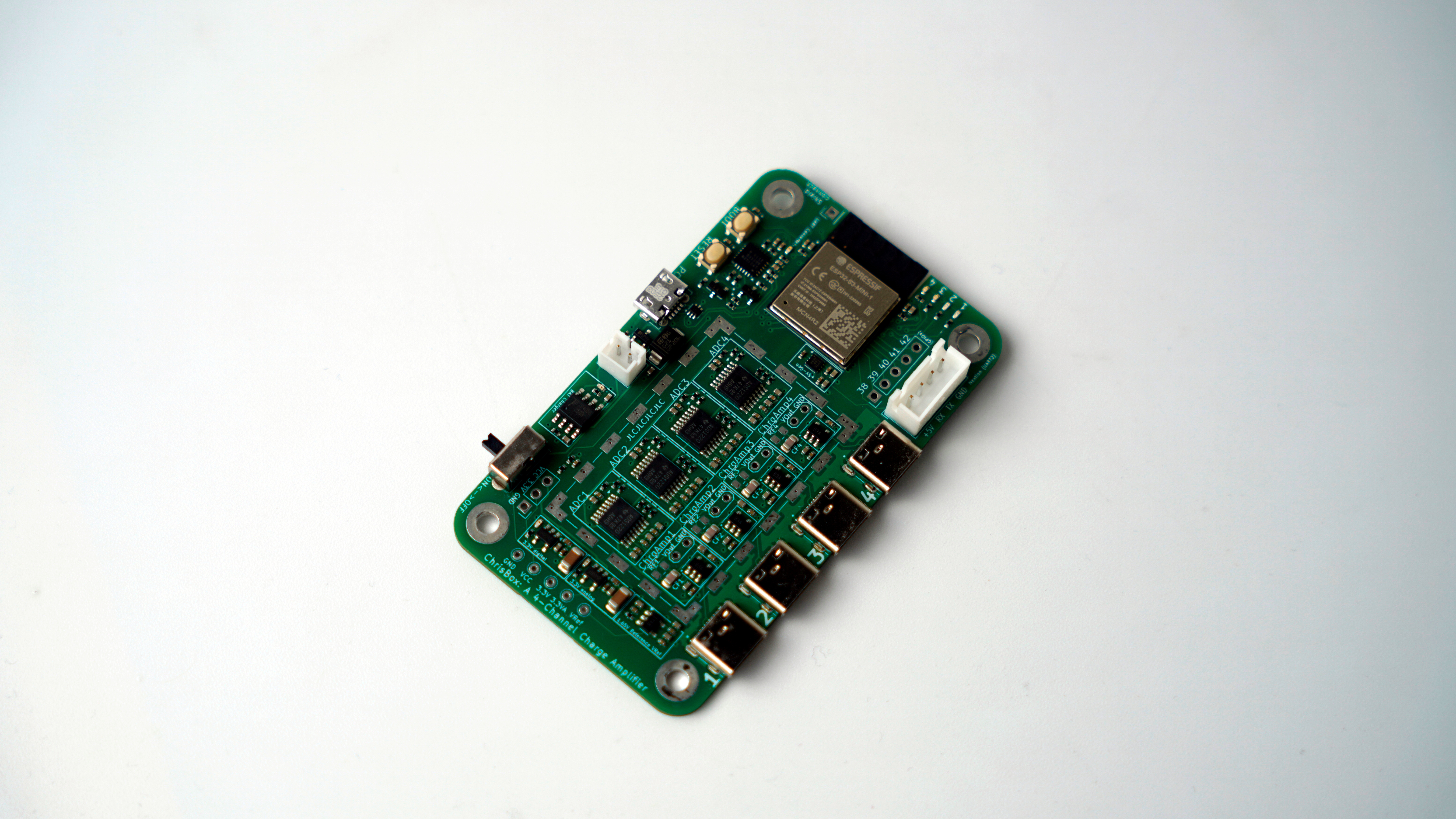
./exports - The .step-export of the ChrisBox PCB../interactive bom - The interactive HTML BOM (made with Interactive Html Bom). It is useful for handsoldering or just looking up which component has to go where../jlcpcb - Output data from the KiCAD JLCPCB tools. This data can be used for ordering a PCB with components. Always re-check the data yourself!./models - Additional footprints and models, which are not included in KiCad and its plugins itself.The other files in this folder are the main KiCad project with schematic and pcb, as well as the sub-schematics (ferro_amplifier and usb_connector).
The design was made with KiCad 8.0. Installed plugins are the Alternate KiCad Library (by Dawid Cislo), the Interactive Html Bom (by qu1ck) and the KiCAD JLCPCB tools (by Bouni).
Additional Footprints or 3D models are found in the ./models folder.
Always check the JLCPCB options yourself! The tools seemed to "forget" some data from time to time.
For ordering instructions refer to ORDERING INSTRUCTIONS. For building instructions refer to BUILDING INSTRUCTIONS.
| Qty | Value | Footprint | References |
|---|---|---|---|
| 36 | 100n | Capacitor_SMD:C_0402_1005Metric | C2, C10, C12, C13, C18, C21, C22, C23, C26, C27, C30, C33, C34, C35, C38, C39 +20 |
| 36 | 10u | Capacitor_SMD:C_0402_1005Metric | C1, C3, C11, C14, C16, C17, C19, C20, C24, C25, C28, C29, C31, C32, C36, C37 +20 |
| 21 | 47 | Resistor_SMD:R_0402_1005Metric | R3, R13, R14, R15, R16, R17, R19, R20, R21, R22, R23, R25, R26, R27, R28, R29 +5 |
| 7 | 10k | Resistor_SMD:R_0402_1005Metric | R6, R7, R40, R44, R47, R49, R52 |
| 7 | 1k | Resistor_SMD:R_0402_1005Metric | R12, R18, R24, R30, R37, R43, R48 |
| 7 | 470 | Resistor_SMD:R_0402_1005Metric | R1, R2, R4, R5, R36, R51, R53 |
| 6 | 0 | Resistor_SMD:R_0402_1005Metric_Pad0.72x0.64mm_HandSolder | R38, R39, R41, R42, R45, R50 |
| 5 | 1u | Capacitor_SMD:C_0402_1005Metric | C15, C72, C74, C76, C78 |
| 5 | TestPoint | TestPoint:TestPoint_THTPad_D1.5mm_Drill0.7mm | TP1, TP2, TP3, TP4, TP5 |
| 4 | 2G | Resistor_SMD:R_0805_2012Metric | RF1, RF2, RF3, RF4 |
| 4 | 360p | Capacitor_SMD:C_0805_2012Metric | CF1, CF2, CF3, CF4 |
| 4 | AD8605ARTZ | Package_TO_SOT_SMD_AKL:SOT-23-5 | U4, U6, U8, U10 |
| 4 | ADS1220xPW | Package_SO:TSSOP-16_4.4x5mm_P0.65mm | U3, U5, U7, U9 |
| 4 | MountingHole_Pad | MountingHole:MountingHole_3.2mm_M3_Pad | H1, H2, H3, H4 |
| 4 | TYPE-C-31-M-12 | TYPE-C-31-M-12:HRO_TYPE-C-31-M-12 | J7, J8, J9, J10 |
| 4 | TestPoint_2Pole | TestPoint:TestPoint_2Pads_Pitch2.54mm_Drill0.8mm | TP6, TP7, TP8, TP9 |
| 3 | LOGO | LOGO | G***, G***, G*** |
| 2 | 100u | Capacitor_SMD:C_1206_3216Metric | C7, C8 |
| 2 | 4.7u | Capacitor_SMD:C_0402_1005Metric | C66, C68 |
| 2 | AP2112K-3.3 | Package_TO_SOT_SMD:SOT-23-5 | U13, U14 |
| 2 | SS8050-G | SS8050-G:TRANS_SS8050-G | Q1, Q2 |
| 1 | 4k7 | Resistor_SMD:R_0402_1005Metric | R46 |
| 1 | BOOT_SWITCH | SKRPABE010:SW_SKRPABE010 | S2 |
| 1 | CP2102N-Axx-xQFN24 | Package_DFN_QFN:QFN-24-1EP_4x4mm_P0.5mm_EP2.6x2.6mm | U12 |
| 1 | Conn_01x01_Pin | Connector_PinHeader_2.54mm:PinHeader_1x01_P2.54mm_Vertical | J5 |
| 1 | Conn_01x03_Pin | Connector_PinHeader_2.54mm:PinHeader_1x03_P2.54mm_Vertical | J1 |
| 1 | Conn_01x04_Socket | Connector_JST:JST_XH_B4B-XH-A_1x04_P2.50mm_Vertical | J3 |
| 1 | Conn_01x05_Pin | Connector_PinHeader_2.54mm:PinHeader_1x05_P2.54mm_Vertical | J2 |
| 1 | DMG2305 | Package_TO_SOT_SMD:SOT-23 | Q3 |
| 1 | D_Schottky | Diode_SMD:D_SMA | D1 |
| 1 | ESP32-S3-MINI-1-N8 | ESP32-S3-MINI-1-N8:XCVR_ESP32-S3-MINI-1-N8 | U2 |
| 1 | JST-PH | Connector_JST:JST_PH_B2B-PH-K_1x02_P2.00mm_Vertical | X1 |
| 1 | LED_CHRG | LED_SMD:LED_0402_1005Metric | D9 |
| 1 | LED_INFO1 | LED_SMD:LED_0402_1005Metric | D5 |
| 1 | LED_INFO2 | LED_SMD:LED_0402_1005Metric | D6 |
| 1 | LED_INFO3 | LED_SMD:LED_0402_1005Metric | D7 |
| 1 | LED_INFO4 | LED_SMD:LED_0402_1005Metric | D8 |
| 1 | LED_PWR1 | LED_SMD:LED_0402_1005Metric | D2 |
| 1 | LED_PWR2 | LED_SMD:LED_0402_1005Metric | D3 |
| 1 | LED_PWR3 | LED_SMD:LED_0402_1005Metric | D4 |
| 1 | LM2775DSG | Package_SON:WSON-8-1EP_2x2mm_P0.5mm_EP0.9x1.6mm_ThermalVias | U15 |
| 1 | NetTie_2 | NetTie:NetTie-2_SMD_Pad0.5mm | NT1 |
| 1 | RESET_SWITCH | SKRPABE010:SW_SKRPABE010 | S3 |
| 1 | RFShield_TwoPieces | Shielding:Laird_Technologies_BMI-S-205-F_38.10x25.40mm_HandSolder_SelfMade | J6 |
| 1 | SK-12D02-VG3 | SK-12D02-VG3:SK12D02VG3 | S1 |
| 1 | TP4056 | MiniLev:SOP-8 | IC1 |
| 1 | TPS73616DBV | Package_TO_SOT_SMD:SOT-23-5 | U1 |
| 1 | USBLC6-2P6 | Package_TO_SOT_SMD:SOT-666 | U11 |
| 1 | USB_B_Micro | Connector_USB:USB_Micro-B_Molex-105017-0001 | J11 |
It measures 78 × 46.3 mm and has 4 copper layers, 1.6 mm thick.
197 parts, built around the AD8605ARTZ-R2, ESP32-S3-MINI-1-N8, LM2775DSG and AP2112K-3.3. The full list of its parts is on this page, with links to each part's symbol and footprint where PCBKit's library has them.
From the TUDA-MUST/ChrisBox repository on GitHub, at the commit this page was made from: the board is PCB/ChrisPCB.kicad_pcb and its schematic PCB/ChrisPCB.kicad_sch. PCBKit opens the board in the browser, with nothing to install.
Its repository states no licence, so its author keeps all rights: ask TUDA-MUST before reusing the design.
TUDA-MUST/Multi-Ferro-DAQ
Measurement Setup to analyze multiple ferroelectric sensors simultaneously


hisashin/qNinja
Open source Real-Time Quantitative PCR Implementation

sparkengineering/hdmi-pmod
HDMI type A receptacle to Digilent Pmod™ breakout board

SzymonGogulski/KICAD_SEE_ELECTRICAL_PROJECTS_PUEIE
University projects related to PCB design and electrical diagram design. 7th semester - course "Design of Electrical and Electronic Systems".


gmlewis/asic-reticulum
SpinalHDL implementation of ASIC hardware for go-reticulum

bipin-vishwakarma/Smart-Pill-Dispenser
Unfinished ESP32-S3 pill-dispenser PCB design study preserved for reference.