2 layers48 × 75 mm
 ttnmapper/ttntrackernode13
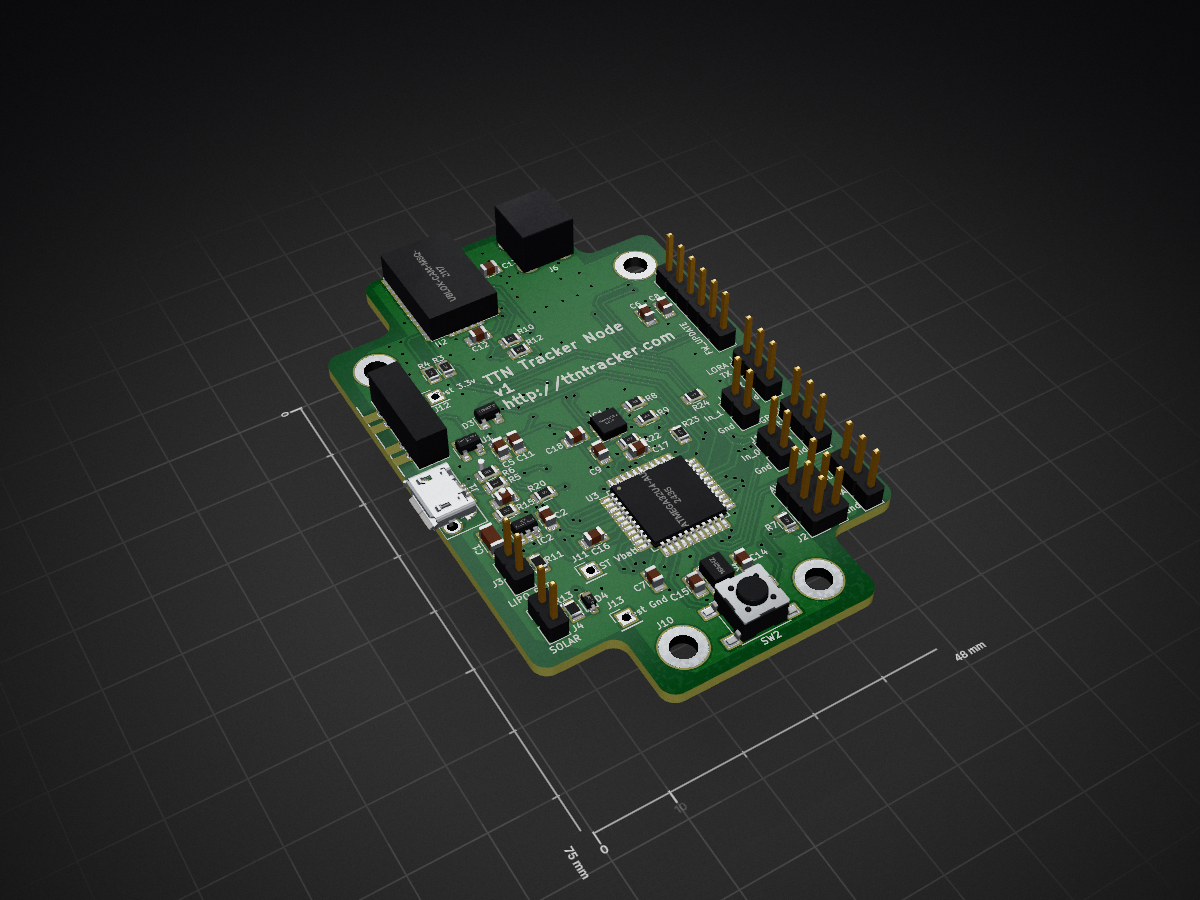
GPS Tracker device
Gps node is an open-source printed circuit board by ttnmapper, from the ttnmapper/ttntrackernode repository on GitHub. It is a 2-layer board of 48 × 75 mm with 84 parts on 111 nets, routed with 1,049 tracks and 130 vias.
It is built around the ATMEGA32U4-AU, MMA8452QT and TLV71333PDBV, with the WS2812B among its other parts. Its parts include 26 resistors, 19 capacitors, 18 connectors, 9 diodes and 6 ICs. It belongs with the radio and wireless boards and the AVR (ATmega, ATtiny) boards of this library.


The TTN Tracker is a Things Network node with a gps, used to map out coverage on TTN Mapper. The device is aimed at end users, but can also be reprogrammed by more advanced users.
Thisrepository contains the schematics used to create the device as well as any additional files and the firmware that was loaded on the device.
The schematics were created using KiCad 4.0.7
These are links to the datasheets of important components used in the design.
| Qty | Value | Footprint | References |
|---|---|---|---|
| 11 | 100nF | Capacitors_SMD:C_0805 | C2, C7, C8, C9, C10, C11, C12, C13, C17, C18, C20 |
| 8 | 4.7k | Resistors_SMD:R_0805 | R1, R2, R7, R10, R12, R22, R23, R26 |
| 4 | 0 | Resistors_SMD:R_0805 | R11, R13, R18, R19 |
| 4 | 22 | Resistors_SMD:R_0805 | R5, R6, R8, R9 |
| 4 | 4.7uF | Capacitors_SMD:C_0805 | C3, C5, C6, C19 |
| 4 | 470 | Resistors_SMD:R_0805 | R14, R20, R21, R24 |
| 4 | Mounting Hole | Mounting_Holes:MountingHole_3.2mm_M3_ISO14580_Pad | J7, J8, J9, J10 |
| 3 | D_Small | gps_node_components:BAS70 | D1, D2, D3 |
| 3 | RESET | Buttons_Switches_SMD:SW_SPST_PTS645 | SW2, SW3, SW4 |
| 2 | 100k | Resistors_SMD:R_0805 | R16, R17 |
| 2 | 220 | Resistors_SMD:R_0805 | R3, R4 |
| 2 | 22pF | Capacitors_SMD:C_0805 | C14, C15 |
| 2 | D_Small | gps_node_components:DB2J411 | D4, D5 |
| 2 | LED | LEDs:LED_0805 | D7, D8 |
| 1 | 10k | Resistors_SMD:R_0805 | R25 |
| 1 | 10uF | Capacitors_SMD:C_1206 | C1 |
| 1 | 16MHz | gps_node_components:QC3CA_16MHz | Y1 |
| 1 | 1uF | Capacitors_SMD:C_0805 | C16 |
| 1 | 2k | Resistors_SMD:R_0805 | R15 |
| 1 | ATMEGA32U4-AU | Housings_QFP:TQFP-44_10x10mm_Pitch0.8mm | U3 |
| 1 | AVR ICSP | Pin_Headers:Pin_Header_Straight_2x03_Pitch2.54mm | J2 |
| 1 | FW_UPDATE | Pin_Headers:Pin_Header_Straight_1x06_Pitch2.54mm | J5 |
| 1 | GPIO_0 | Pin_Headers:Pin_Header_Straight_1x02_Pitch2.54mm | J17 |
| 1 | GPIO_1 | Pin_Headers:Pin_Header_Straight_1x02_Pitch2.54mm | J18 |
| 1 | I2C GPS | Pin_Headers:Pin_Header_Straight_1x03_Pitch2.54mm | J15 |
| 1 | LED_Small_ALT | LEDs:LED_0805 | D6 |
| 1 | LIPO_BAT | Pin_Headers:Pin_Header_Straight_1x02_Pitch2.54mm | J3 |
| 1 | MCP73831/2 | TO_SOT_Packages_SMD:SOT-23-5 | IC2 |
| 1 | MMA8452Q | gps_node_components:MMA8452Q | IC1 |
| 1 | Polyfuse | gps_node_components:bourns polyfuse | F1 |
| 1 | RN2483 | drawn_by_jpmeijers:RN2483 | U4 |
| 1 | SMA | gps_node_components:SMA_BOARD_UPRIGHT | J6 |
| 1 | SOLAR | Pin_Headers:Pin_Header_Straight_1x02_Pitch2.54mm | J4 |
| 1 | SW_SP3T | gps_node_components:DP3T_switch | SW1 |
| 1 | TEST Vbatt | Socket_Strips:Socket_Strip_Straight_1x01_Pitch2.54mm | J11 |
| 1 | TLV71333PDBV | TO_SOT_Packages_SMD:SOT-23-5 | U1 |
| 1 | Test 3.3v | Socket_Strips:Socket_Strip_Straight_1x01_Pitch2.54mm | J12 |
| 1 | Test Gnd | Socket_Strips:Socket_Strip_Straight_1x01_Pitch2.54mm | J13 |
| 1 | UART GPS | Pin_Headers:Pin_Header_Straight_1x03_Pitch2.54mm | J16 |
| 1 | UART RF | Pin_Headers:Pin_Header_Straight_1x03_Pitch2.54mm | J14 |
| 1 | USB_OTG | gps_node_components:Molex_Microusb | J1 |
| 1 | WS2812B | LEDs:LED_WS2812B-PLCC4 | LED1 |
| 1 | ublox-cam-m8q-0 | drawn_by_jpmeijers:ublox-cam-m8q-0 | U2 |
It measures 48 × 75 mm and has 2 copper layers, 1.6 mm thick.
84 parts, built around the ATMEGA32U4-AU, MMA8452QT, TLV71333PDBV and WS2812B. The full list of its parts is on this page, with links to each part's symbol and footprint where PCBKit's library has them.
From the ttnmapper/ttntrackernode repository on GitHub, at the commit this page was made from: the board is schematic/v1/gps_node.kicad_pcb. PCBKit opens the board in the browser, with nothing to install.
Its repository states no licence, so its author keeps all rights: ask ttnmapper before reusing the design.


AEFeinstein/Super-2020-Swadge-HW
The hardware for a hardware badge (Swadge) for Magfest 2020


MouseBiteLabs/Super-Game-Boy-Plus
A replacement circuit board for improving the Super Game Boy, or for creating a standalone Game Boy game for the SNES.

Kiogora/esp32_lora_gateway
/ ) | | ( ( | | | | \ \| | ( ) |/ ) \ ) ) | | | || || ( (| | | | (/|)||| \))\)| || (C)2013 Semtech-Cycleo

AyushShuklaaa7/USB-C-to-I2C-Interface-FT201XS-
A compact and simple USB-C to I2C interface built using the FT201XS IC. This board is designed to provide an easy way to communicate with I2C devices directly from a computer via USB.

