2 layers30 × 26 mm

 tsmiltonAgents/20260721_countdown
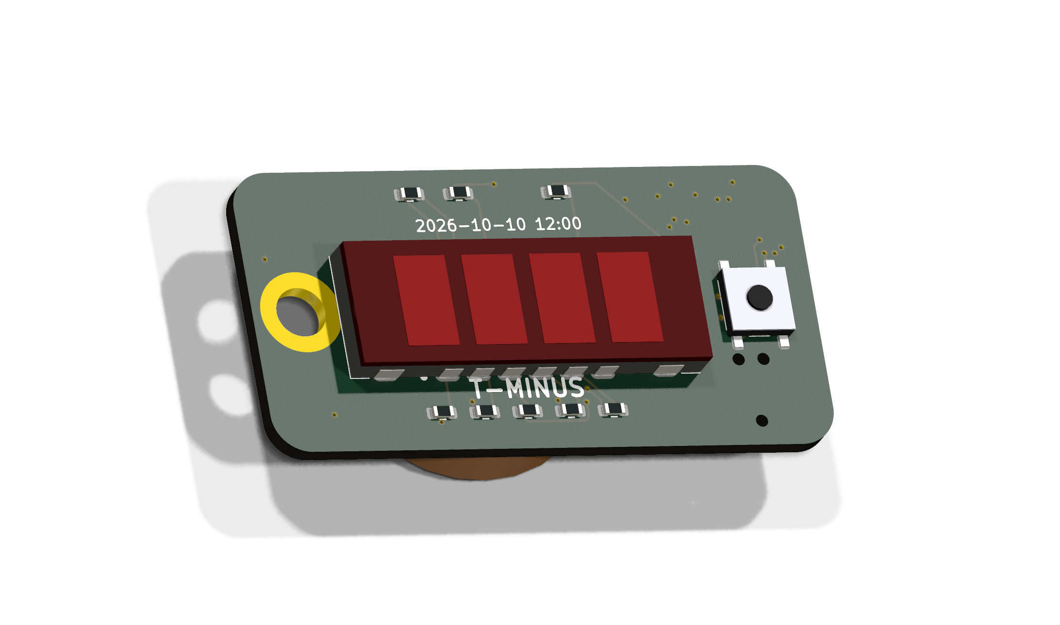
A 46 × 23 mm, 4-layer keyring PCB that counts down the hours to 10 October 2026, midday on a red 4-digit 7-segment display.
Countdown is an open-source printed circuit board by tsmiltonAgents, from the tsmiltonAgents/20260721_countdown repository on GitHub. It is a 4-layer board of 46 × 23 mm with 24 parts on 36 nets, routed with 280 tracks and 37 vias.
It is built around the STM32L031G6U6, BS-08-B2AA001 and TS-1187A-B-A-B, with the XL-SA2401SRWC among its other parts. Its parts include 9 resistors, 8 capacitors, 1 IC, 1 connector and 1 switch. It belongs with the STM32 boards of this library.


A 46 × 23 mm, 4-layer keyring PCB that counts down the hours to
10 October 2026, midday on a red 4-digit 7-segment display. Powered by a
CR2032, it keeps time for years in deep sleep; press the button and the
hours remaining glow for 8 seconds. Under 100 hours to go it switches to
minutes (decimal point lit as the marker). At T-0 it shows 0.0.0.0.
make flash right after make and the clock is correct to seconds.| Path | What |
|---|---|
hw/countdown/ | KiCad 10 project (schematic, PCB, DRC/ERC reports) |
hw/lib/ | Custom symbols + footprints (display, holder, switch, hole) |
hw/scripts/ | The full generation pipeline (see below) |
fab/ | JLCPCB order files: gerbers.zip, bom.csv, cpl.csv |
fw/ | Firmware (bare-metal C, no HAL; make && make flash) |
docs/renders/ | Verification renders (incl. 3D-model views) |
hw/mech/ | build123d part models (via earthtojake/text-to-cad CAD skill) → STEP |
designlog.md | Full engineering narrative, decisions and reviews |
prompts.md | Prompt log |
Everything is generated — schematic, footprints, placement, routing, fab files — by scripts (KiCad 10 CLI + pcbnew Python + a custom A* router):
python3 hw/scripts/gen_footprints.py     # custom footprints from datasheet dims
python3 hw/scripts/gen_sch_countdown.py  # schematic + intended netlist
# ERC + netlist verification, then:
./hw/scripts/route_own.sh                # place, fanout power, planes, route, DRC
./hw/scripts/render_views.sh             # eyeball it
# fab outputs:
<kicad-python> hw/scripts/export_fab.py hw/countdown/countdown.kicad_pcb fab/See fab/ORDERING.md for the click-by-click instructions, including the
one thing you MUST eyeball in their UI: part rotations in the placement
preview (especially U1) before paying.
| Qty | Value | Footprint | References |
|---|---|---|---|
| 8 | 330R | R_0603_1608Metric | R1, R2, R3, R4, R5, R6, R7, R8 |
| 3 | 100nF | C_0603_1608Metric | C1, C2, C3 |
| 2 | 10uF | C_0603_1608Metric | C5, C6 |
| 2 | 15pF | C_0603_1608Metric | C7, C8 |
| 1 | 10k | R_0603_1608Metric | R9 |
| 1 | 1uF | C_0603_1608Metric | C4 |
| 1 | 32.768kHz | Crystal_SMD_3215-2Pin_3.2x1.5mm | Y1 |
| 1 | BS-08-B2AA001 | BS-08-B2AA001 | BT1 |
| 1 | KeyringHole | KeyringHole_4mm | H1 |
| 1 | STM32L031G6U6 | QFN-28_4x4mm_P0.5mm | U1 |
| 1 | TC2030-SWD | Tag-Connect_TC2030-IDC-NL_2x03_P1.27mm_Vertical | J1 |
| 1 | TS-1187A-B-A-B | SW_TS-1187A | SW1 |
| 1 | XL-SA2401SRWC | XL-SA2401SRWC | DS1 |

slemanz/chronolog
STM32-based temperature data logger with RTC, NOR flash storage, LCD and Wi-Fi. Hardware and firmware.

captainchapster/Eigentime32
A self-contained pocket watch that keeps its own time for a decade. No GPS, one coin cell, one PCB.

mohamedyanis/BaroAxel-Brain
STM32L0 MCU based PCB for Industrial Instrumentation Applications designed using KiCad.

rappet/ferris-badge
Small badge running on a coin cell using a STM32L031G6U with embassy.


Engineer162/CANSAT-M2-2026
This repository contains all the sources for a highly advanced CANSAT based on an STM32 MCU and featuring a rechargeable lithium polymer battery.

dangiu/PicoMemcard
Emulating PSX Memory Card (or controller) using a Raspberry Pi Pico
It measures 46 × 23 mm and has 4 copper layers, 1.6 mm thick.
24 parts, built around the STM32L031G6U6, BS-08-B2AA001, TS-1187A-B-A-B and XL-SA2401SRWC. The full list of its parts is on this page, with links to each part's symbol and footprint where PCBKit's library has them.
From the tsmiltonAgents/20260721_countdown repository on GitHub, at the commit this page was made from: the board is hw/countdown/countdown.kicad_pcb and its schematic hw/countdown/countdown.kicad_sch. PCBKit opens the board in the browser, with nothing to install.
Its repository states no licence, so its author keeps all rights: ask tsmiltonAgents before reusing the design.