2 layers39.6 × 7.5 mm
Hellen1-power5
rusefi/hellen-miata-NB2
a rusEFI board with a 72 pin connector. Works for a Mazda Miata NB2 or any generic 8 cylinder vehicle :)
19 parts
 ts-manuel/VideoFrame5
The slowest video player with 7-Colors
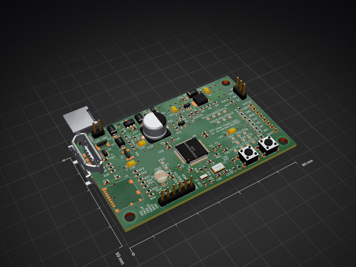
VideoFrame is an open-source printed circuit board by ts-manuel, from the ts-manuel/VideoFrame repository on GitHub, published under the GPL-3.0 licence. It is a 4-layer board of 80 × 50 mm with 123 parts on 109 nets, routed with 828 tracks and 169 vias.
It is built around the STM32F405RGT6, SY6280AAC and HT7533-1, with the MP2451DT, USBLC6-2SC6 and SS14 among its other parts. Its parts include 49 resistors, 31 capacitors, 6 ICs, 6 connectors and 4 diodes. It belongs with the lEDs and displays boards and the STM32 boards of this library.


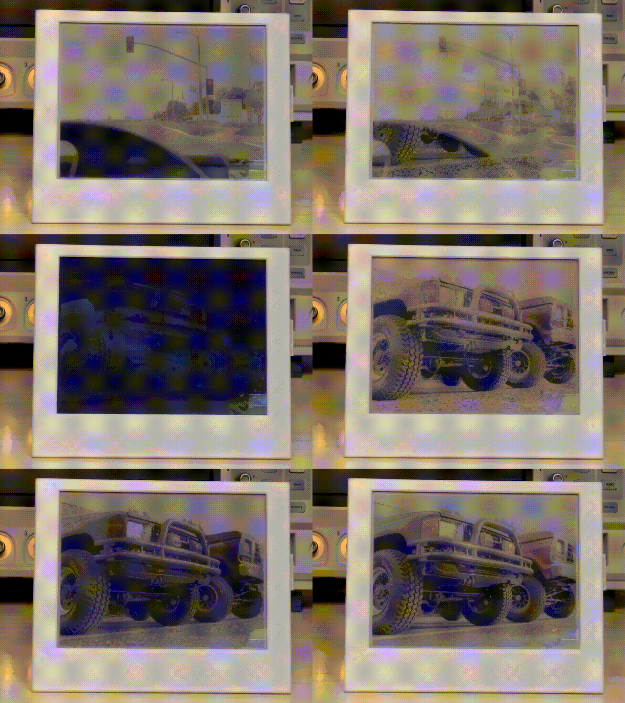
This is a digital picture frame that plays movies at one frame per minute. Images appear on a 7-Color ePaper display. The whole movie is stored as a sequence of jpeg images on an SD-Card. An STM32 microcontroller does the jpeg decoding and drives the display.
e-Paper displays maintain the displayed image without needing any power. The image is updated every 24 minutes and an update cycle takes 18 seconds. Since the device is in sleep mode for the majority of the time, power draw is minimal and the batteries last for a decent amount of time.
The device is powered by 6 AA batteries.
For more info check out the full log on hackaday.io
File > ImportGeneral > Existing Project into Workspace then click nextstm32 select the project and click finishConnect the USB cable, check that the correct drivers are installed
Enter DFU mode by pressing the RESET while holding down the BOOT button
Use the following command to flash the firmware
dfu-util -a0 -s 0x08000000 0 -D "Video Frame.bin"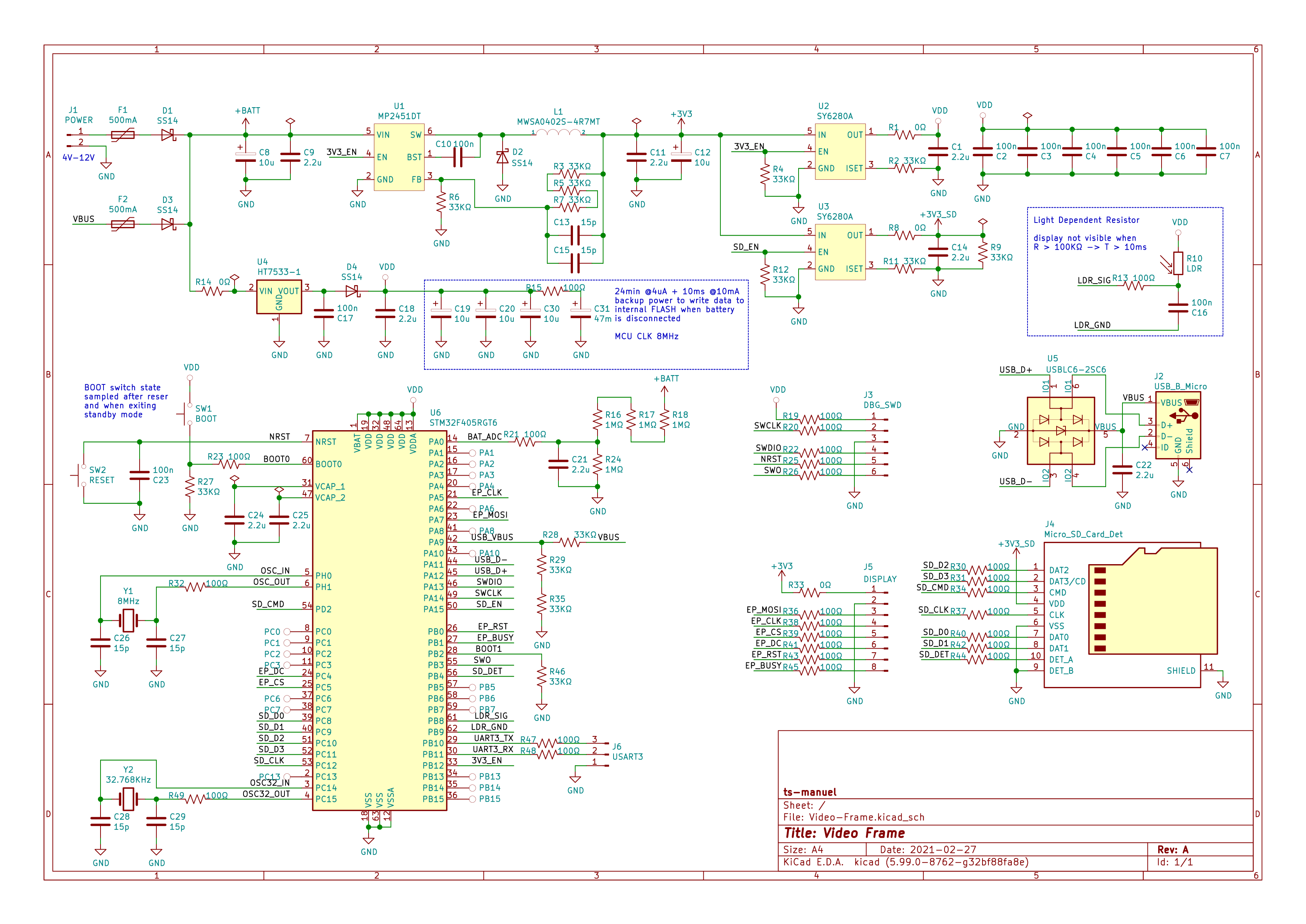
The USB emulates a serial port that can be used to configure the device. During normal operation, a timer interrupt wakes the microcontroller every 24 minutes to update the display. An update cycle can also be triggered by pressing the RESET button. By default, the microcontroller goes back into sleep mode immediately after the display has been updated. By pressing the BOOT button while the display is updating, the microcontroller starts listening for commands on the serial port. After 60 seconds of inactivity, the microcontroller goes back to sleep.
The following is a list of commands that can be entered.
load FOLDER/FILE.jpg loads the specified file from the SD card
update triggers an update cycle
sleep enters sleep mode immediately
The following project is shared "as is", with the sole objective of being useful. The creator of the described piece of hardware and its associated software cannot guarantee its correct functioning under any circumstance. The author of this project will not be held responsible for any material, personal or economic losses to you or any third parties that may arise from using this design. This project will not be used under any circumstances on systems whose responsibility is critical, or from which people's lives depend upon, directly or indirectly.
| Qty | Value | Footprint | References |
|---|---|---|---|
| 26 | 100Ω | Resistor_SMD:R_0603_1608Metric | R13, R15, R19, R20, R21, R22, R23, R25, R26, R30, R31, R32, R34, R36, R37, R38 +10 |
| 14 | 33KΩ | Resistor_SMD:R_0603_1608Metric | R2, R3, R4, R5, R6, R7, R9, R11, R12, R27, R28, R29, R35, R46 |
| 10 | 100n | Capacitor_SMD:C_0603_1608Metric | C2, C3, C4, C5, C6, C7, C10, C16, C17, C23 |
| 9 | 2.2u | Capacitor_SMD:C_0603_1608Metric | C1, C9, C11, C14, C18, C21, C22, C24, C25 |
| 6 | 15p | Capacitor_SMD:C_0603_1608Metric | C13, C15, C26, C27, C28, C29 |
| 5 | 10u | Capacitor_Tantalum_SMD:CP_EIA-3216-10_Kemet-I | C8, C12, C19, C20, C30 |
| 4 | 0Ω | Resistor_SMD:R_0603_1608Metric | R1, R8, R14, R33 |
| 4 | 1MΩ | Resistor_SMD:R_0603_1608Metric | R16, R17, R18, R24 |
| 4 | SS14 | Diode_SMD:D_SMA | D1, D2, D3, D4 |
| 2 | 500mA | Fuse:Fuse_1812_4532Metric | F1, F2 |
| 2 | SY6280A | Package_TO_SOT_SMD:SOT-23-5_HandSoldering | U2, U3 |
| 1 | 32.768KHz | Crystal:Crystal_SMD_3215-2Pin_3.2x1.5mm | Y2 |
| 1 | 47m | Capacitor_SMD:CP_Elec_10x7.7 | C31 |
| 1 | 8MHz | Crystal:Crystal_SMD_5032-2Pin_5.0x3.2mm | Y1 |
| 1 | BOOT | Button_Switch_THT:SW_PUSH_6mm | SW1 |
| 1 | DBG_SWD | Connector_PinHeader_2.54mm:PinHeader_1x06_P2.54mm_Vertical | J3 |
| 1 | DISPLAY | Connector_PinHeader_2.54mm:PinHeader_1x08_P2.54mm_Horizontal | J5 |
| 1 | HT7533-1 | Package_TO_SOT_SMD:SOT-89-3 | U4 |
| 1 | LDR | OptoDevice:R_LDR_5.1x4.3mm_P3.4mm_Vertical | R10 |
| 1 | MP2451DT | Package_TO_SOT_SMD:SOT-23-6_Handsoldering | U1 |
| 1 | MWSA0402S-4R7MT | Inductor_SMD:L_Murata_LQH55DN_5.7x5.0mm | L1 |
| 1 | Micro_SD_Card_Det | Connector_Card:microSD_HC_Molex_104031-0811 | J4 |
| 1 | PA1 | TestPoint:TestPoint_Pad_D1.0mm | TP1 |
| 1 | PA10 | TestPoint:TestPoint_Pad_D1.0mm | TP7 |
| 1 | PA2 | TestPoint:TestPoint_Pad_D1.0mm | TP2 |
| 1 | PA3 | TestPoint:TestPoint_Pad_D1.0mm | TP3 |
| 1 | PA4 | TestPoint:TestPoint_Pad_D1.0mm | TP4 |
| 1 | PA6 | TestPoint:TestPoint_Pad_D1.0mm | TP5 |
| 1 | PA8 | TestPoint:TestPoint_Pad_D1.0mm | TP6 |
| 1 | PB13 | TestPoint:TestPoint_Pad_D1.0mm | TP18 |
| 1 | PB14 | TestPoint:TestPoint_Pad_D1.0mm | TP19 |
| 1 | PB15 | TestPoint:TestPoint_Pad_D1.0mm | TP20 |
| 1 | PB5 | TestPoint:TestPoint_Pad_D1.0mm | TP12 |
| 1 | PB6 | TestPoint:TestPoint_Pad_D1.0mm | TP14 |
| 1 | PB7 | TestPoint:TestPoint_Pad_D1.0mm | TP16 |
| 1 | PC0 | TestPoint:TestPoint_Pad_D1.0mm | TP8 |
| 1 | PC1 | TestPoint:TestPoint_Pad_D1.0mm | TP9 |
| 1 | PC13 | TestPoint:TestPoint_Pad_D1.0mm | TP17 |
| 1 | PC2 | TestPoint:TestPoint_Pad_D1.0mm | TP10 |
| 1 | PC3 | TestPoint:TestPoint_Pad_D1.0mm | TP11 |
| 1 | PC6 | TestPoint:TestPoint_Pad_D1.0mm | TP13 |
| 1 | PC7 | TestPoint:TestPoint_Pad_D1.0mm | TP15 |
| 1 | POWER | Connector_PinHeader_2.54mm:PinHeader_1x02_P2.54mm_Vertical | J1 |
| 1 | RESET | Button_Switch_THT:SW_PUSH_6mm | SW2 |
| 1 | STM32F405RGT6 | Package_QFP:LQFP-64_10x10mm_P0.5mm | U6 |
| 1 | USART3 | Connector_PinHeader_2.54mm:PinHeader_1x03_P2.54mm_Vertical | J6 |
| 1 | USBLC6-2SC6 | Package_TO_SOT_SMD:SOT-23-6 | U5 |
| 1 | USB_B_Micro | Connector_MicroUSB:USB_Micro-B_CUI_Devices-UJ2-MIBH-G-SMT-TR | J2 |
rusefi/hellen-miata-NB2
a rusEFI board with a 72 pin connector. Works for a Mazda Miata NB2 or any generic 8 cylinder vehicle :)

Ben-Blair/Rocket-Build
Senior capstone project: demonstrate closed-loop lateral guidance of a high power rocket using forward canards, and handle the canard-wake-on-aft-fin interference problem correctly.

felixznr/ALBERT
Albert I was a rhesus macaque monkey and the first mammal launched on a rocket (V-2 Rocket "Blossom No. 3") on June 18, 1948.

rogerclarkmelbourne/STM32_Pill_Boards
Various STM32 boards in a form factor similar to the Maple Mini or Blue Pill board


Kilan777/HomeDeck
Jarvis HomeDeck: a Raspberry Pi CM4 carrier board and voice-assistant software for a 7-inch smart display (KiCad hardware, generated from Python, plus the Python/JS assistant)


cUDGk/vrc-fbt-hardware
VRChat向けフルボディトラッキング基板 — ハブ+デイジーチェーン端末・数と位置を自由に変更可能・KiCad/OpenSCAD一式
It measures 80 × 50 mm and has 4 copper layers, 1.6 mm thick.
123 parts, built around the STM32F405RGT6, SY6280AAC, HT7533-1 and MP2451DT. The full list of its parts is on this page, with links to each part's symbol and footprint where PCBKit's library has them.
From the ts-manuel/VideoFrame repository on GitHub, at the commit this page was made from: the board is pcb/Video-Frame.kicad_pcb and its schematic pcb/Video-Frame.kicad_sch. PCBKit opens the board in the browser, with nothing to install.
Its repository publishes it under the GPL-3.0 licence: you may reuse it on that licence's terms (keep the author's notice, and for a copyleft licence share your changes alike).