2 layers78 × 90 mm
Multicart
trwgQ26xxx/FLT_ART_CU1_Multicart
Multicart for Fiat Lancia Tester\Alfa Romeo Tester\Check Up 1
44 parts

 trwgQ26xxx/FLT_ART_CU1_Multicart
Multicart for Fiat Lancia Tester\Alfa Romeo Tester\Check Up 1
Multicart is an open-source printed circuit board by trwgQ26xxx, from the trwgQ26xxx/FLT_ART_CU1_Multicart repository on GitHub. It is a 2-layer board of 78 × 89.5 mm with 46 parts on 64 nets, routed with 973 tracks and 107 vias.
It is built around the AT89C2051-12PU, 74HC00D and 74LS573PC, with the MAX810M among its other parts. Its parts include 16 resistors, 13 capacitors, 8 ICs, 2 switches and 1 connector. It belongs with the 8051 (CH55x, STC, AT89) boards of this library.


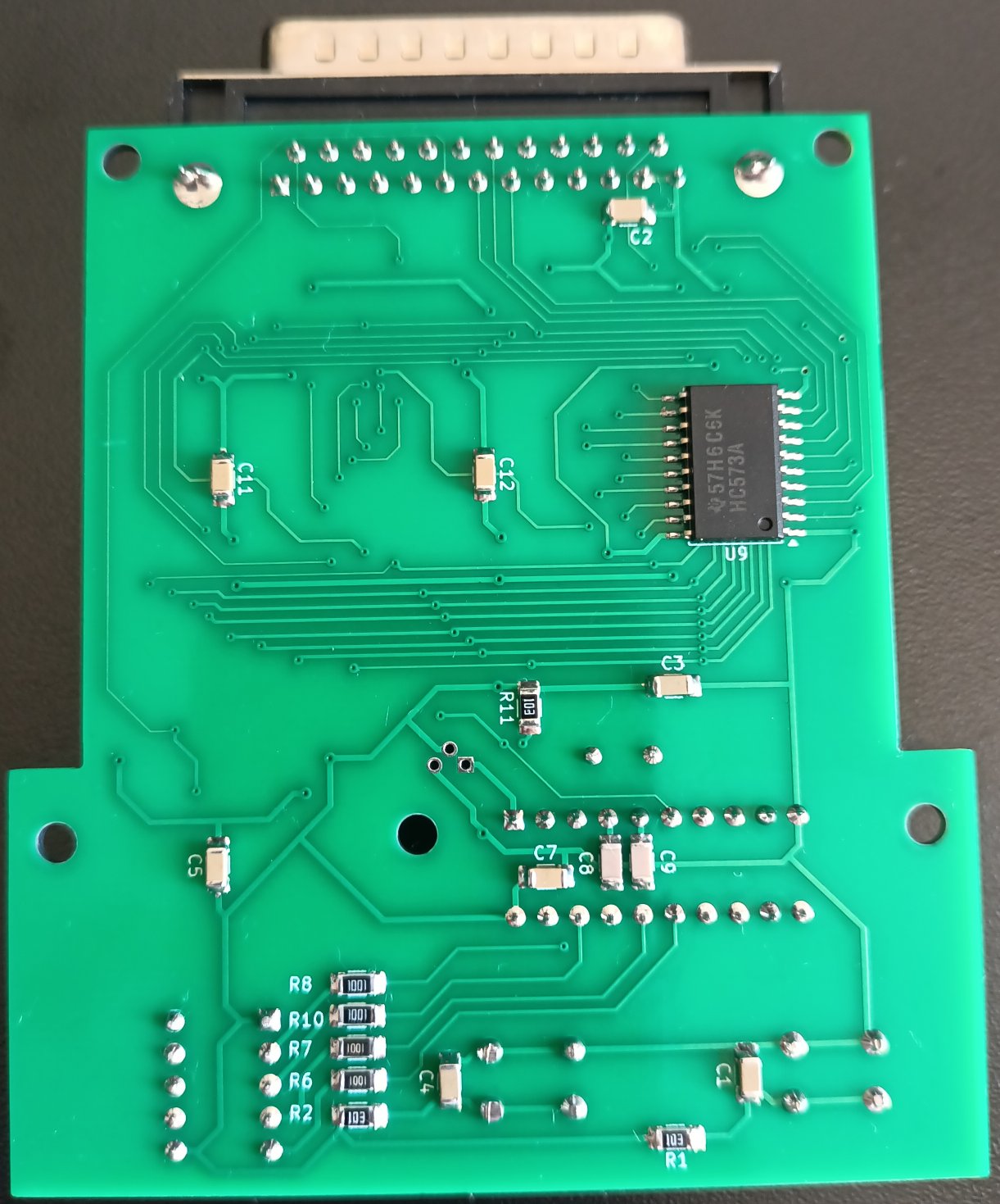
A multicart ROM module that replaces eight standard FLT modules. It contains eight ROM sets stored in a 512kB (4Mbit) flash memory, which can be switched on the fly.
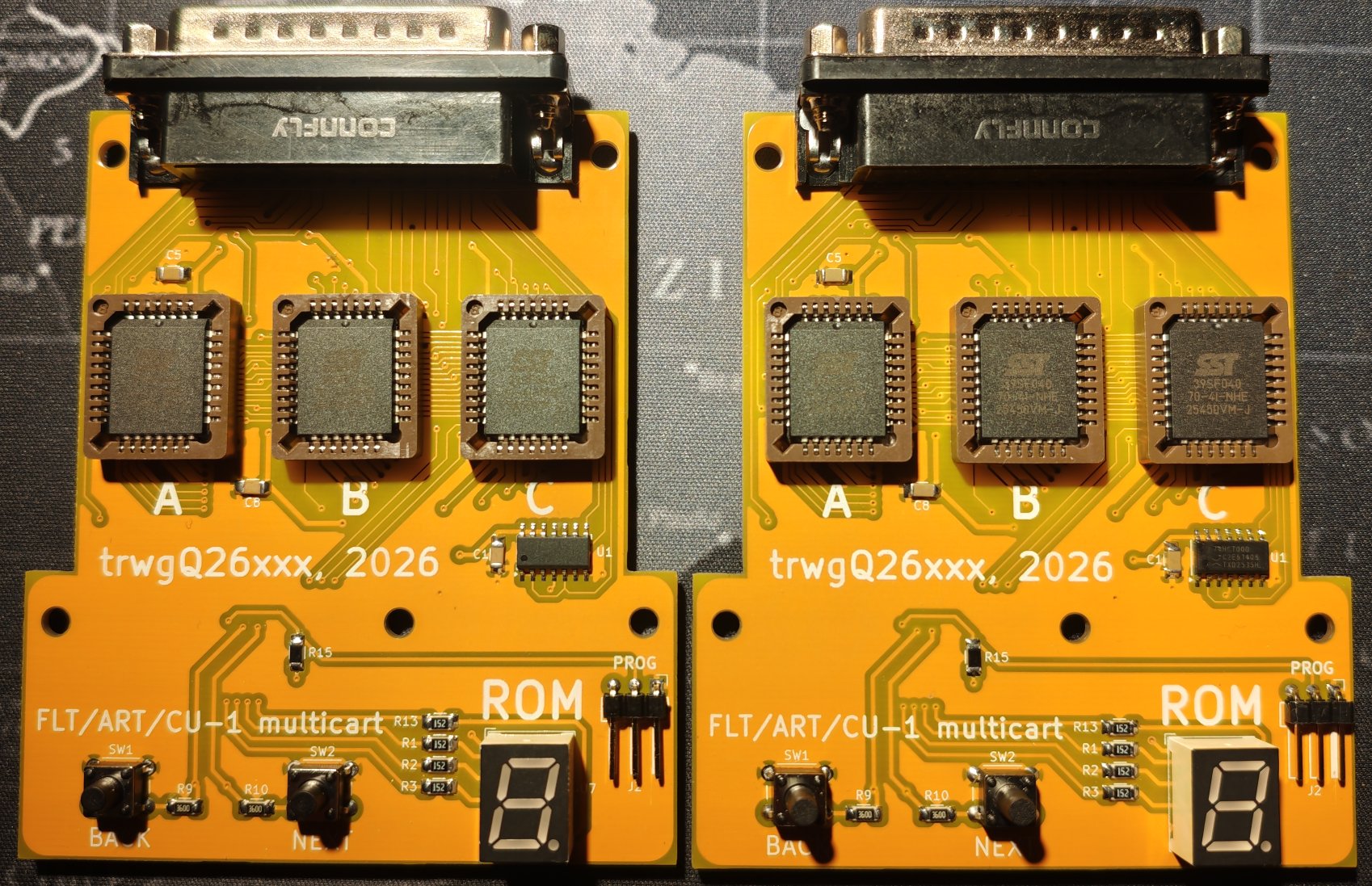
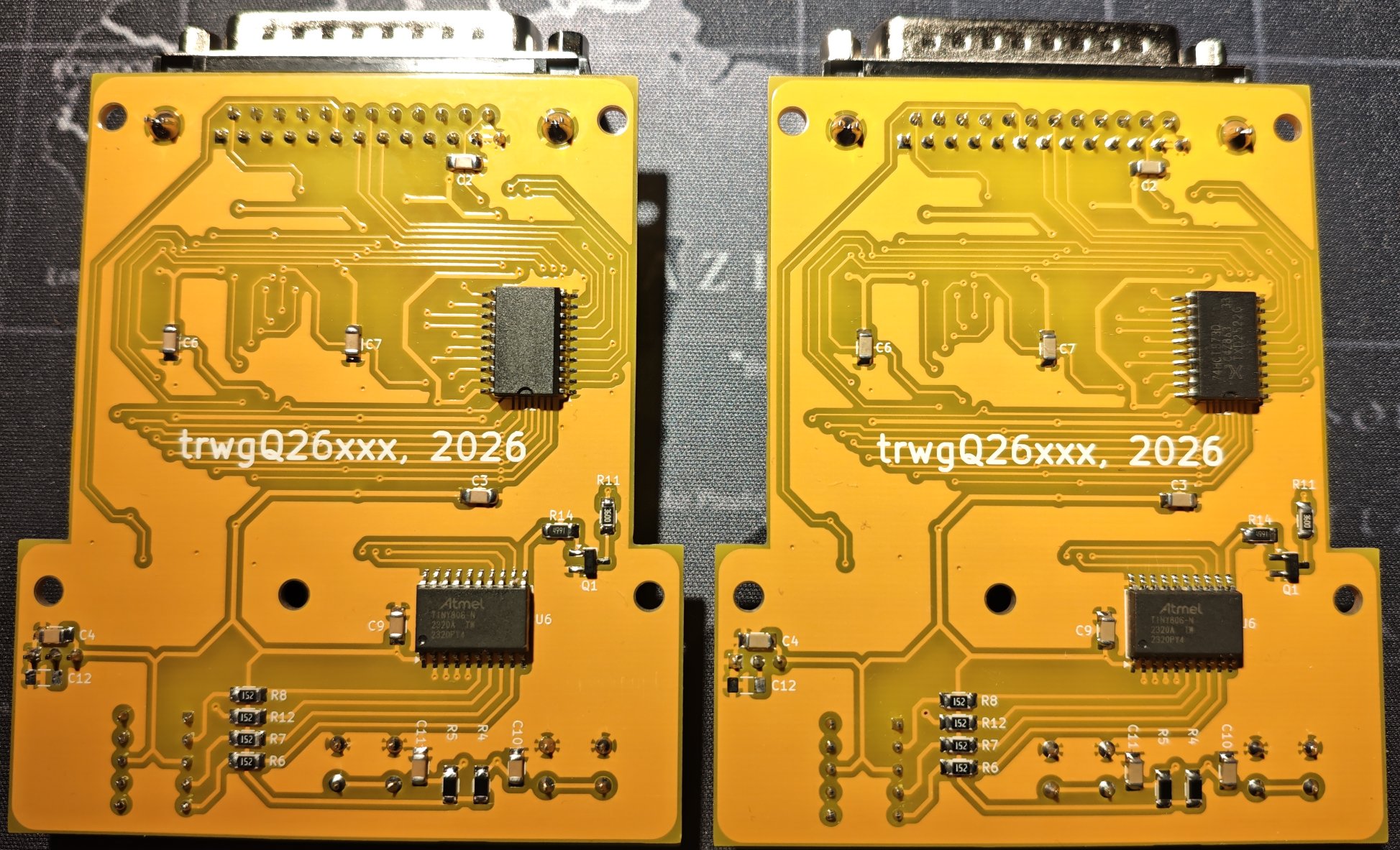
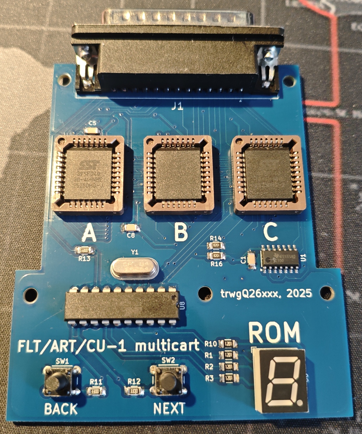
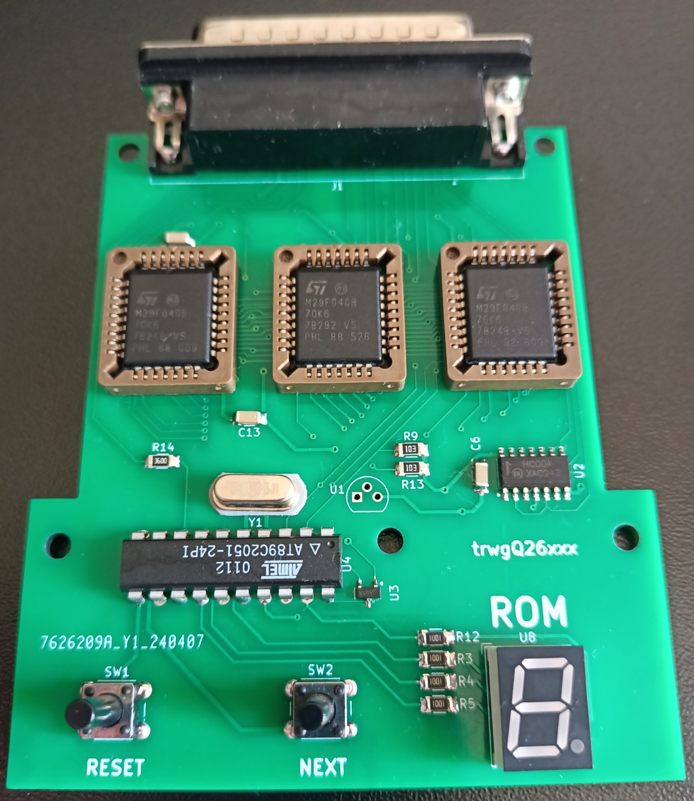
Two variants are implemented: one using an Atmel AT89C2051 MCU (revisions A - green and B - blue), and another based on a Microchip ATtiny806 (revision C - yellow).
I do not consent to the use of all or part of the project for commercial purposes!
Nie wyrażam zgody na wykorzystanie całości bądź części projektu w celach zarobkowych!
Shield: 
This work is licensed under a Creative Commons Attribution-NonCommercial-ShareAlike 4.0 International License.

Switching modules (ROMs) is accomplished by pressing the BACK and NEXT keys. With each press, a dot lights up on the display for the FLT reset time (approximately 200 ms). The display indicates the number of the currently running module.
The FLASH memories used, of 39SF040 type (or equivalent), have a capacity of 512kB. Considering that the largest FLT modules ROMs are 64kB, I designed the multicart's capacity to accomodate 8 modules.
The FLASH memory contents can be changed according to the following principles.
| ROM index | Base offset |
|---|---|
| 1 | 0x00000 |
| 2 | 0x10000 |
| 3 | 0x20000 |
| 4 | 0x30000 |
| 5 | 0x40000 |
| 6 | 0x50000 |
| 7 | 0x60000 |
| 8 | 0x70000 |
Let's assume we want to load the module at index 3, for which the base offset is 0x20000.
| ROM | SIZE | The ROM given is PRESENT in the module being loaded at index 3 | The ROM given is NOT PRESENT in the module being loaded at index 3 |
|---|---|---|---|
| A | 8kB | Load the content of ROM A into FLASH memory A addresses 0x20000-0x21FFF.Fill addresses 0x22000-0x2FFFF of FLASH memory A with 0xFF. | Fill addresses 0x20000-0x2FFFF of FLASH memory A with 0xFF. |
| B | 32kB | Load the content of ROM B into FLASH memory B addresses 0x28000-0x2FFFF. Fill addresses 0x20000-0x27FFF of FLASH memory B with 0xFF. | ROM B is always present. |
| B | 64kB | Load the content of ROM B into FLASH memory B addresses 0x20000-0x2FFFF. | ROM B is always present. |
| C | 32kB | Load the content of ROM C into FLASH memory C addresses 0x28000-0x2FFFF. Fill addresses 0x20000-0x27FFF of FLASH memory C with 0xFF. | Fill addresses 0x20000-0x2FFFF of FLASH memory C with 0xFF. |
| C | 64kB | Load the content of ROM C into FLASH memory C addresses 0x20000-0x2FFFF. | Fill addresses 0x20000-0x2FFFF of FLASH memory C with 0xFF. |
It should be noted here that the utilization of FLASH memory A is at most 12.5%, as only 8kB of each 64kB bank is utilized. However, I opted for this solution to simplify the process of preparing Flash memory content, given the use of identical offsets.
Use the APX810-40SA as the reset supervisor for the AT89C2051 MCU (U7 on the PCB) in revisions A and B.
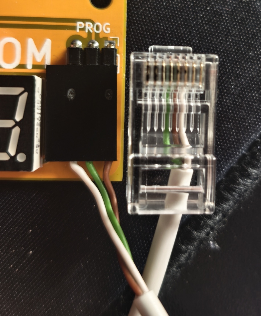
Wiring the MPLAB ICD5 8P8C Connector to the Multicart PROG Connector (Revision C):
| SIGNAL | PROG pin | 8P8C pin |
|---|---|---|
| GND | 1 | 5 |
| UPDI | 2 | 4 |
| VCC | 3 | 6 |
| Qty | Value | Footprint | References |
|---|---|---|---|
| 11 | 100n | Capacitor_SMD:C_1206_3216Metric_Pad1.33x1.80mm_HandSolder | C1, C2, C3, C4, C5, C6, C7, C8, C9, C12, C13 |
| 8 | 1k | Resistor_SMD:R_1206_3216Metric_Pad1.30x1.75mm_HandSolder | R1, R2, R3, R4, R5, R8, R9, R10 |
| 5 | 10k | Resistor_SMD:R_1206_3216Metric_Pad1.30x1.75mm_HandSolder | R6, R7, R14, R15, R16 |
| 5 | ~ | MountingHole:MountingHole_3.2mm_M3_DIN965 | H1, H2, H3, H4, H5 |
| 3 | 330 | Resistor_SMD:R_1206_3216Metric_Pad1.30x1.75mm_HandSolder | R11, R12, R13 |
| 3 | SST39SF040 | Package_LCC:PLCC-32_11.4x14.0mm_P1.27mm | U3, U4, U5 |
| 2 | 22p | Capacitor_SMD:C_1206_3216Metric_Pad1.33x1.80mm_HandSolder | C10, C11 |
| 1 | 3.6864MHz | Crystal:Crystal_HC49-4H_Vertical | Y1 |
| 1 | 74HC00 | Package_SO:SOIC-14_3.9x8.7mm_P1.27mm | U1 |
| 1 | 74LS573 | Package_SO:SOIC-20W_7.5x12.8mm_P1.27mm | U2 |
| 1 | AT89C2051-12P | Package_DIP:DIP-20_W7.62mm | U8 |
| 1 | BACK | Button_Switch_THT:SW_PUSH_6mm | SW1 |
| 1 | MAX810 | Package_TO_SOT_SMD:SOT-23 | U7 |
| 1 | MODULE | Connector_Dsub:DSUB-25_Male_Horizontal_P2.77x2.84mm_EdgePinOffset4.94mm_Housed_MountingHolesOffset7.48mm | J1 |
| 1 | NEXT | Button_Switch_THT:SW_PUSH_6mm | SW2 |
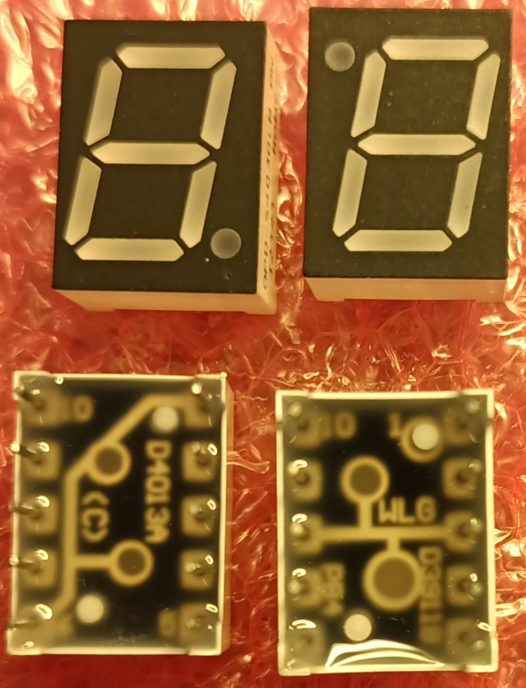
| 1 | SA39-11SRWA | Display_7Segment:Sx39-1xxxxx | U6 |
trwgQ26xxx/FLT_ART_CU1_Multicart
Multicart for Fiat Lancia Tester\Alfa Romeo Tester\Check Up 1

stonedDiscord/Automatenplatinen
Reverse engineerte Hardware aus deutschen Spielautomaten.


oberrow/i8088-computer
Code for an i8088-based non-PC compatible breadboard computer


It measures 78 × 89.5 mm and has 2 copper layers, 1.6 mm thick.
46 parts, built around the AT89C2051-12PU, 74HC00D, 74LS573PC and MAX810M. The full list of its parts is on this page, with links to each part's symbol and footprint where PCBKit's library has them.
From the trwgQ26xxx/FLT_ART_CU1_Multicart repository on GitHub, at the commit this page was made from: the board is PCB/89c2051_version/Multicart.kicad_pcb and its schematic PCB/89c2051_version/Multicart.kicad_sch. PCBKit opens the board in the browser, with nothing to install.
Its repository states no licence, so its author keeps all rights: ask trwgQ26xxx before reusing the design.