2 layers127 × 121.9 mm

 soster/dtZ8015
A simple 8 Bit computer based on the Z80 CPU
Dtz80-complete is an open-source printed circuit board by soster, from the soster/dtZ80 repository on GitHub. It is a 2-layer board of 200.7 × 149.9 mm with 107 parts on 188 nets, routed with 7,575 tracks and 1,390 vias.
It is built around the 74HC245D, 74LS32SC and 74LS573PC, with the 74HC00D, 74HCT138D and 74LS04PC among its other parts. Its parts include 34 resistors, 23 connectors, 18 ICs, 16 capacitors and 2 crystals. It belongs with the retro computing and games boards of this library.


This started as a project during the second Corona lockdown, where I had to much free time. I wanted to design my own 8 Bit computer and decided to use the Z80 CPU. The first idea was to use a MOS 6502 because a variant of that powers the C64, a computer I used much in my childhood. The Z80 is easier to source where I live so I used that instead.
I started on breadboards but quickly discovered the limits of that so I soldered some prototypes and finally designed some PCBs with kicad.
The bus is compatible to the Bus of the RC2014 Z80 computer, so I can exchange expansion cards.
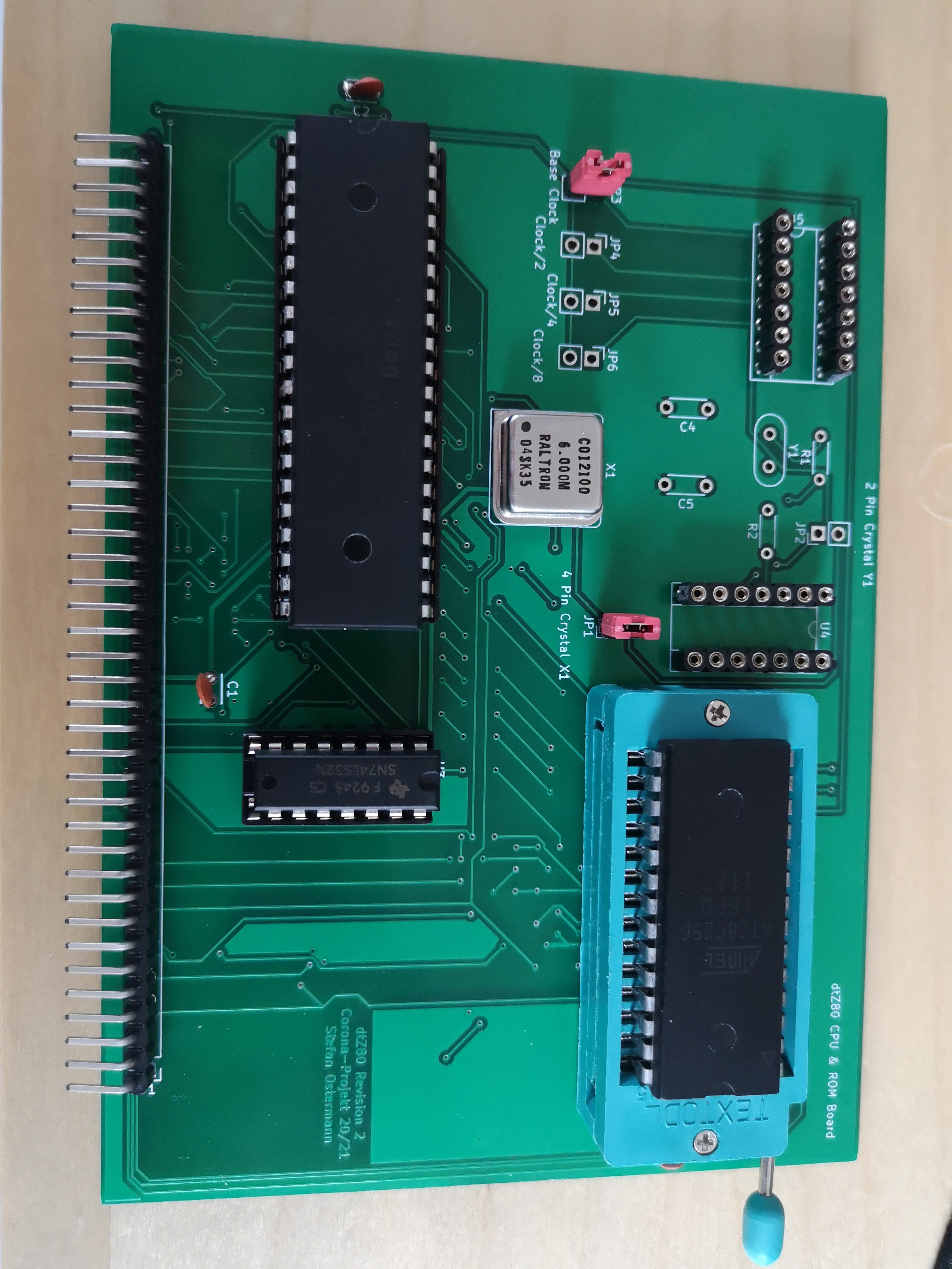
This documentation now covers the new "Black Edition" of the dtZ80 (Rev 1), a larger board without the need to use extension cards. Previous prototypes had a common bus board and extension cards for the CPU, RAM etc. All software for the previous prototypes can be found at asm/prototype for historical reasons.
The dtZ80 uses a Z80 CPU with clocked with 7.3728 Mhz (which doubles as a clock for serial communication), a Z80 SIO for serial communication, a CTC counter timer, 32kb of RAM and 32kb of ROM and a AY-3-8910A sound chip. It uses a single seven segment display for debugging purposes and a 4 line, 20 characters per line LCD for text output.
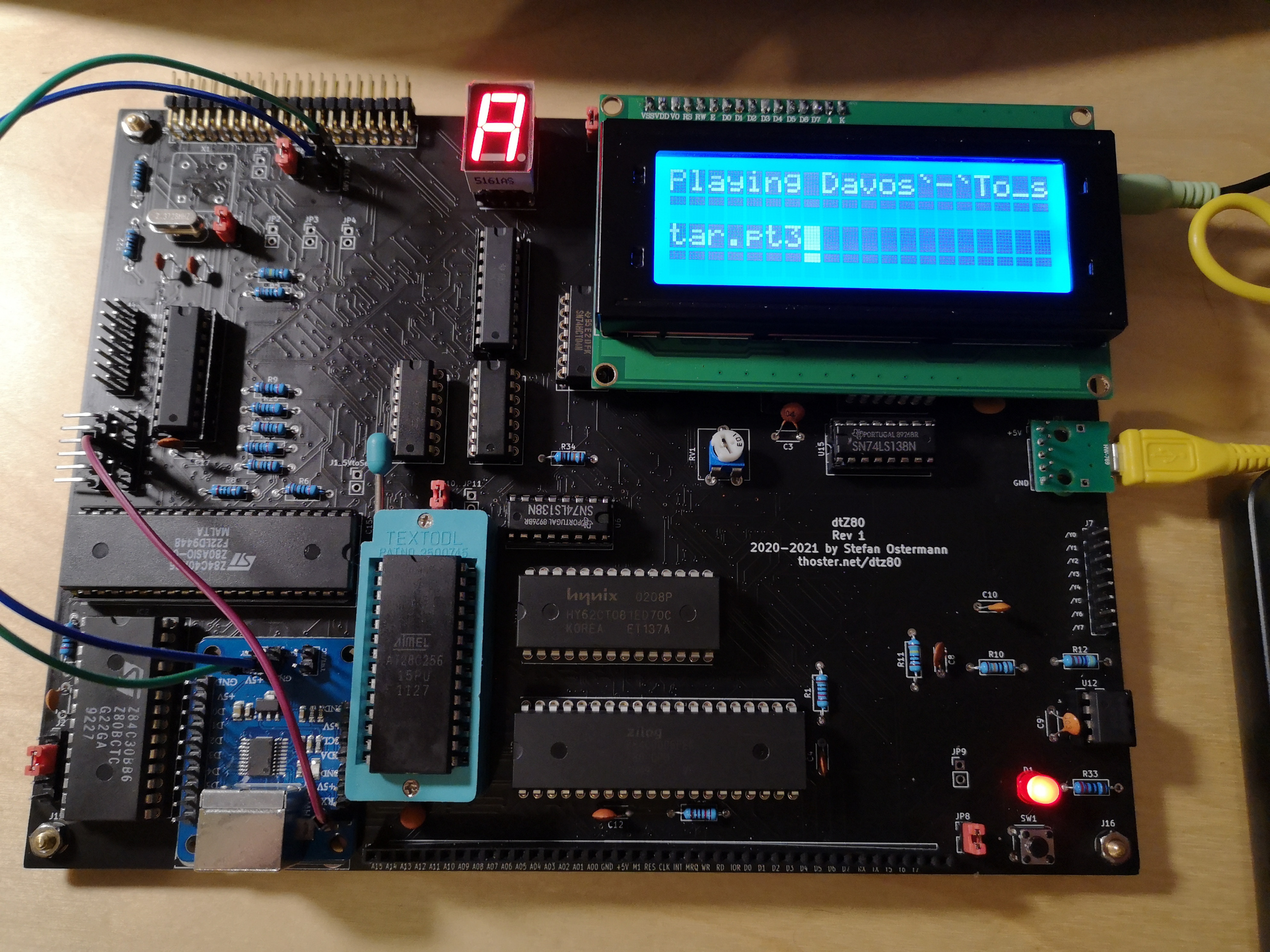
Address lines are assigned by a 74LS138 IC (U6) which activates or deactivates the correct ICs.
$00: I/O port 7 segment (A0-A7=0)
$04: LCD command I/O port (A5=1)
$05: LCD data I/O port (A5=1,A0=1)
$40: SIO Data Channel A
$42: SIO Control Channel A
$60: CTC Channel 0
$61: CTC Channel 1
$62: CTC Channel 2
$63: CTC Channel 3
$80: Sound Register
$81: Sound DataThe black edition uses a 4 line, 20 column LCD Display (2004A V1.1) probably based on the HD44780 Chip (Datasheet). It behaves strangely if we send character by character to it, it uses line 3 after line 1 and the lines 2 and 4 are not usable. We have to manually set the DDRAM address holding the character position according to the current line:
Line 1: $00 - $13
Line 2: $40 - $53
Line 3: $14 - $27
Line 4: $54 - $67
I assume this is due to backwarts compatibility to 2 line displays.
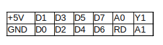
The 8 Bit parallel Interface is used to connect a lcd screen mainly. Due to an error while designing the pcb, it has the following pins (GND=Pin 1):
The serial interface is provided by the Z80 SIO chip (SI0/0). It has two channels, A (J1) and B (J6). The clock is provided by the CTC chip for channel A. If you want to use channel B, you have to connect the clock from the pin CTS from J1 to CTS on J6. Please note that RX and TX are labeled from the point of view of the external device, RX is connected to TX on the SIO and vice versa (this maybe was a stupid decistion).
If you are working with linux and you have a usb to serial converter connected to /dev/ttyUSB0 you can use screen to enter serial terminal mode:
screen /dev/ttyUSB0 19200To enter serial mode of the dtZ80 simply press enter now.
Screen commands consist of "C-a" or ctrl+a (holding down the control key, and then pressing the 'a' key, then releasing both), to enter the command input mode, then commands may be entered with another key stroke. To disconnect from the session: Ctrl+a, Ctrl+d, you can then use this to reattach to the session:
screen -rTo quit screen and close connection: ctrl+a, k.
TODO
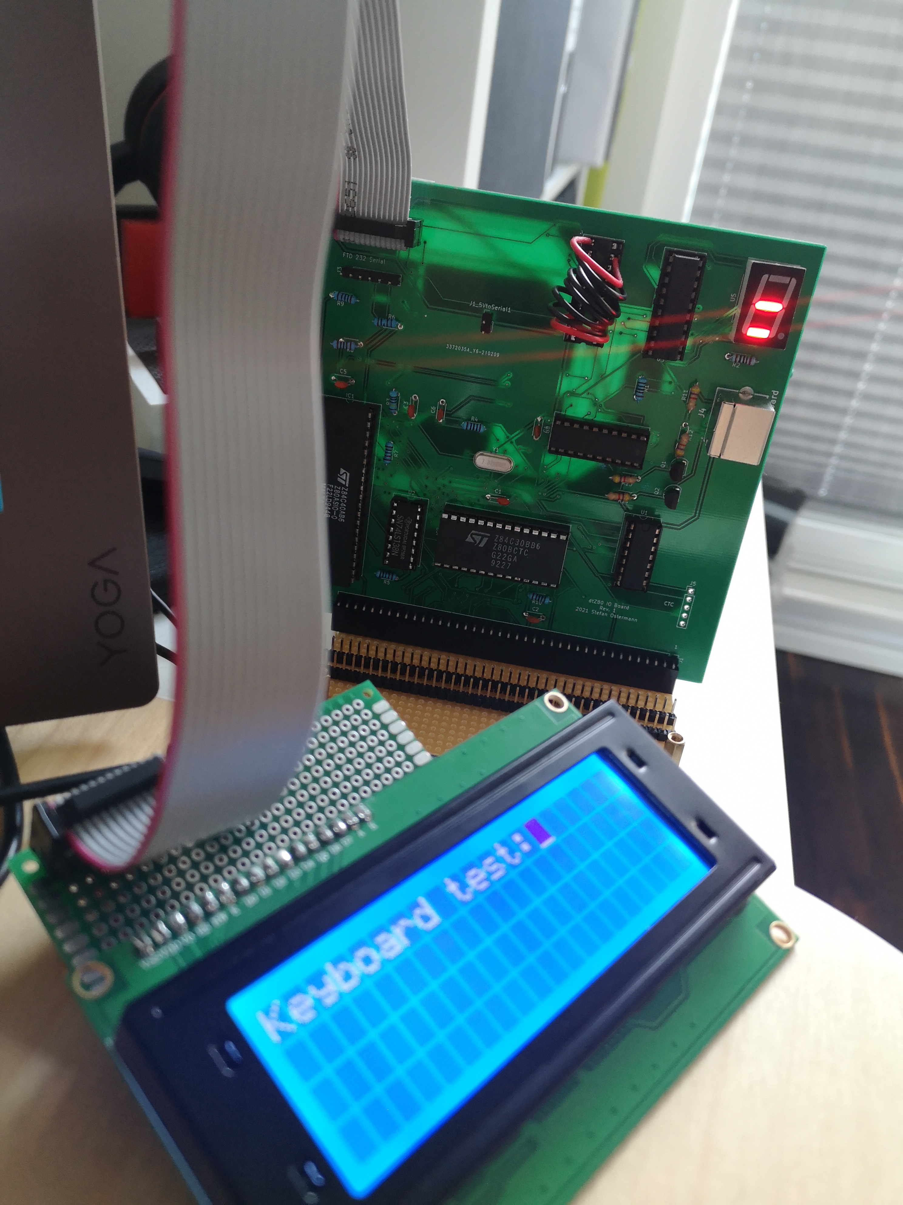
For ps/2 keyboard to serial conversion I use a "PS2 Keyboard Driver Serial Port Transmission Module".
TODO
The simulator ticks from https://github.com/z88dk/z88dk can be used as a simulator. It provides character output for debugging purposes. Use it like this on assembled binary files:
z88dk.z88dk-ticks -iochar 5 bios.bin-iochar 5 puts out characters just like for the LCD of the dtz80.
Graphics is not finished yet. These are some ideas: Based on: TMS9918A Problem: Works only with DRAM for SRAM Looks like you will need to latch the address bits 8-15 when RAS goes low Connect (/CAS0 AND /CAS1) to /OE on the SRAM and use one of them for A16 also Important: Clock 10.738635 Mhz, Type MP107-E for video timing Use schematics from: https://github.com/jblang/TMS9918A
| Qty | Value | Footprint | References |
|---|---|---|---|
| 10 | Conn_01x01 | MountingHole:MountingHole_3.2mm_M3_DIN965_Pad | J13, J14, J15, J16, J17, J18, J19, J20, J21, J22 |
| 9 | 100n | Capacitor_THT:C_Disc_D4.3mm_W1.9mm_P5.00mm | C3, C4, C5, C6, C11, C12, C15, C16, C17 |
| 9 | 330 | Resistor_THT:R_Axial_DIN0207_L6.3mm_D2.5mm_P10.16mm_Horizontal | R13, R14, R16, R17, R18, R19, R20, R21, R33 |
| 6 | 1k | Resistor_THT:R_Axial_DIN0207_L6.3mm_D2.5mm_P10.16mm_Horizontal | R4, R22, R29, R30, R31, R32 |
| 6 | 2K | Resistor_THT:R_Axial_DIN0207_L6.3mm_D2.5mm_P10.16mm_Horizontal | R6, R8, R9, R23, R24, R25 |
| 4 | 10k | Resistor_THT:R_Axial_DIN0207_L6.3mm_D2.5mm_P10.16mm_Horizontal | R1, R10, R15, R34 |
| 3 | 3k | Resistor_THT:R_Axial_DIN0207_L6.3mm_D2.5mm_P10.16mm_Horizontal | R26, R27, R28 |
| 2 | 10K | Resistor_THT:R_Axial_DIN0207_L6.3mm_D2.5mm_P10.16mm_Horizontal | R5, R7 |
| 2 | 1M | Resistor_THT:R_Axial_DIN0207_L6.3mm_D2.5mm_P10.16mm_Horizontal | R2, R11 |
| 2 | 22pF | Capacitor_THT:C_Disc_D4.3mm_W1.9mm_P5.00mm | C1, C2 |
| 2 | 4.7u | Capacitor_THT:C_Radial_D6.3mm_H5.0mm_P2.50mm | C13, C14 |
| 2 | 74LS32 | Package_DIP:DIP-14_W7.62mm_Socket | U1, U9 |
| 2 | 74LS573 | Package_DIP:DIP-20_W7.62mm_Socket | U7, U13 |
| 1 | 100nF | Capacitor_THT:C_Disc_D4.3mm_W1.9mm_P5.00mm | C8 |
| 1 | 10nF | Capacitor_THT:C_Disc_D4.3mm_W1.9mm_P5.00mm | C9 |
| 1 | 10uF | Capacitor_THT:C_Disc_D4.3mm_W1.9mm_P5.00mm | C10 |
| 1 | 1K | Resistor_THT:R_Axial_DIN0207_L6.3mm_D2.5mm_P10.16mm_Horizontal | R3 |
| 1 | 28C256 | dtz80:DIP-28_W15.24mm_Socket_Large_Holes | U3 |
| 1 | 47K | Resistor_THT:R_Axial_DIN0207_L6.3mm_D2.5mm_P10.16mm_Horizontal | R12 |
| 1 | 5161AS | dtz80:7SegmentLED_LTS6760_LTS6780 | U10 |
| 1 | 5V Serial | Connector_PinHeader_2.54mm:PinHeader_1x02_P2.54mm_Vertical | J1_5VtoSerial1 |
| 1 | 74HC00 | Package_DIP:DIP-14_W7.62mm_Socket | U16 |
| 1 | 74HC245 | Package_DIP:DIP-20_W7.62mm_Socket | U8 |
| 1 | 74HCT138 | Package_DIP:DIP-16_W7.62mm_Socket | U15 |
| 1 | 74LS04 | Package_DIP:DIP-14_W7.62mm_Socket | U5 |
| 1 | 74LS138 | Package_DIP:DIP-16_W7.62mm_Socket | U6 |
| 1 | 74LS393 | Package_DIP:DIP-14_W7.62mm_Socket | U4 |
| 1 | 7Seg Enable | Connector_PinHeader_2.54mm:PinHeader_1x02_P2.54mm_Vertical | JP7 |
| 1 | 8 Bit Output | Connector_PinHeader_2.54mm:PinHeader_2x07_P2.54mm_Vertical | J4 |
| 1 | Auto Reset | Connector_PinHeader_2.54mm:PinHeader_1x02_P2.54mm_Vertical | JP8 |
| 1 | Base Clock | Connector_PinHeader_2.54mm:PinHeader_1x02_P2.54mm_Vertical | JP1 |
| 1 | CTC | Connector_PinHeader_2.54mm:PinHeader_1x05_P2.54mm_Vertical | J2 |
| 1 | CXO_DIP8 | Oscillator:Oscillator_DIP-8 | X1 |
| 1 | Clock/2 | Connector_PinHeader_2.54mm:PinHeader_1x02_P2.54mm_Vertical | JP2 |
| 1 | Clock/4 | Connector_PinHeader_2.54mm:PinHeader_1x02_P2.54mm_Vertical | JP3 |
| 1 | Clock/8 | Connector_PinHeader_2.54mm:PinHeader_1x02_P2.54mm_Vertical | JP4 |
| 1 | Crystal | Crystal:Crystal_HC52-8mm_Vertical | Y1 |
| 1 | Enable Lines | Connector_PinHeader_2.54mm:PinHeader_1x08_P2.54mm_Vertical | J7 |
| 1 | External Clock | Connector_PinHeader_2.54mm:PinHeader_1x03_P2.54mm_Vertical | J8 |
| 1 | FT_232 A | Connector_PinHeader_2.54mm:PinHeader_1x06_P2.54mm_Vertical | J1 |
| 1 | FT_232 B | Connector_PinHeader_2.54mm:PinHeader_1x06_P2.54mm_Vertical | J6 |
| 1 | HM62256 | Package_DIP:DIP-28_W15.24mm_Socket | U11 |
| 1 | IEI External | Connector_PinHeader_2.54mm:PinHeader_1x02_P2.54mm_Vertical | JP9 |
| 1 | JACK_TRS | dtz80:Tayda_3.5mm_stereo_TRS_jack_A-853 | J10 |
| 1 | LCD | Connector_PinHeader_2.54mm:PinHeader_1x16_P2.54mm_Vertical | J3 |
| 1 | Micro USB | Connector_PinHeader_2.54mm:PinHeader_1x05_P2.54mm_Vertical | J12 |
| 1 | NE555P | Package_DIP:DIP-8_W7.62mm | U12 |
| 1 | POWER | LED_THT:LED_D3.0mm | D1 |
| 1 | RC2014Bus | Connector_PinHeader_2.54mm:PinHeader_1x40_P2.54mm_Vertical | J5 |
| 1 | ROM Off | Connector_PinHeader_2.54mm:PinHeader_1x02_P2.54mm_Vertical | JP11 |
| 1 | ROM On | Connector_PinHeader_2.54mm:PinHeader_1x02_P2.54mm_Vertical | JP10 |
| 1 | R_POT | Potentiometer_THT:Potentiometer_ACP_CA9-V10_Vertical | RV1 |
| 1 | Reset | Button_Switch_THT:SW_TH_Tactile_Omron_B3F-10xx | SW1 |
| 1 | System Bus | Connector_PinHeader_2.54mm:PinHeader_2x20_P2.54mm_Vertical | J9 |
| 1 | X1 Clock | Connector_PinHeader_2.54mm:PinHeader_1x02_P2.54mm_Vertical | JP5 |
| 1 | Y1 Clock | Connector_PinHeader_2.54mm:PinHeader_1x02_P2.54mm_Vertical | JP6 |
| 1 | YM Parallel IO | Connector_PinHeader_2.54mm:PinHeader_2x09_P2.54mm_Vertical | J11 |
| 1 | YM2149 | Package_DIP:DIP-40_W15.24mm_Socket | U14 |
| 1 | Z80CPU | Package_DIP:DIP-40_W15.24mm_Socket | U2 |
| 1 | Z80CTC | Package_DIP:DIP-28_W15.24mm_Socket | IC2 |
| 1 | Z80SIO | Package_DIP:DIP-40_W15.24mm_Socket | IC1 |


Trilobyte-CPU/8-bit-computer
A DIY 8-bit computer built mostly with discrete logic chips

sammothxc/6502-stacked-cardputer
my Ben Eater 6502 Computer Kit personal repo


hkzlab/CGA_Redux
The Color Graphics Adapter Redux board is a more or less faithful clone of the original IBM CGA, based on the original schematics

It measures 200.7 × 149.9 mm and has 2 copper layers, 1.6 mm thick.
107 parts, built around the 74HC245D, 74LS32SC, 74LS573PC and 74HC00D. The full list of its parts is on this page, with links to each part's symbol and footprint where PCBKit's library has them.
From the soster/dtZ80 repository on GitHub, at the commit this page was made from: the board is schema/dtz80-complete/dtz80-complete.kicad_pcb. PCBKit opens the board in the browser, with nothing to install.
Its repository states no licence, so its author keeps all rights: ask soster before reusing the design.