4 layers254.9 × 150.1 mm

 trnila/ftdi_quad_lin
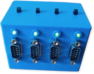
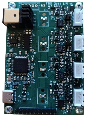
FTDI Quad-LIN is an FTDI-based board that enables communication with up to 4 LIN channels.
Ftdi quad lin is an open-source printed circuit board by trnila, from the trnila/ftdi_quad_lin repository on GitHub. It is a 2-layer board of 55 × 80 mm with 157 parts on 133 nets, routed with 856 tracks and 170 vias.
It is built around the TJA1029T, 74HC595 and AP2112K-3.3, with the FT4232HL, MMBT2222A and 1N4148W among its other parts. Its parts include 46 resistors, 43 capacitors, 24 diodes, 12 transistors and 8 ICs.


FTDI Quad-LIN is an FTDI-based board that enables communication with up to 4 LIN channels.
Install dkms driver for sllin module:
$ ./install_driver.shThen run following commands to:
ldattach@.service on USB plug-insllin.network file to automatically bringup slcan interface up$ sudo apt install ftdi-eeprom
$ ./setup.sh some_serial_numberConnect all channels to 2x PCAN-USB Pro, then install peak driver:
$ wget https://www.peak-system.com/quick/PLIN-Linux-Driver -O plin_linux_driver.tar.gz
$ tar -xf plin_linux_driver.tar.gz
$ cd peak-lin-driver-1.4.0
$ make
$ sudo make install
Then test all channels as masters by sending frames to the connected PCAN-USB device:
$ uv run pytest| Qty | Value | Footprint | References |
|---|---|---|---|
| 28 | 10k | Resistor_SMD:R_0805_2012Metric | R2, R11, R13, R15, R18, R22, R24, R25, R26, R27, R28, R30, R31, R32, R33, R34 +12 |
| 24 | 100nF | Capacitor_SMD:C_0805_2012Metric | C3, C10, C11, C12, C13, C14, C17, C18, C19, C20, C25, C26, C27, C28, C29, C38 +8 |
| 12 | MMBT2222A | Package_TO_SOT_SMD:SOT-23 | Q1, Q2, Q3, Q4, Q5, Q6, Q7, Q8, Q9, Q10, Q11, Q12 |
| 9 | 1k | Resistor_SMD:R_0805_2012Metric | R1, R10, R12, R14, R16, R17, R19, R20, R21 |
| 8 | 100n | Capacitor_SMD:C_0805_2012Metric_Pad1.18x1.45mm_HandSolder | C30, C31, C32, C33, C34, C35, C36, C37 |
| 8 | ~ | Diode_SMD:D_SOD-323_HandSoldering | D1, D2, D3, D4, D5, D6, D7, D8 |
| 5 | Jumper_2_Open | TestPoint:TestPoint_2Pads_Pitch2.54mm_Drill0.8mm | JP5, JP6, JP7, JP8, JP9 |
| 4 | 1M | Resistor_SMD:R_0805_2012Metric | R23, R29, R35, R41 |
| 4 | 1N4148W | Diode_SMD:D_SOD-323_HandSoldering | D10, D11, D12, D13 |
| 4 | 1nF | Capacitor_SMD:C_0805_2012Metric | C21, C22, C23, C24 |
| 4 | ESD1LIN24 | Diode_SMD:D_SOD-323_HandSoldering | D9, D18, D19, D20 |
| 4 | LED | ftdi_quad_lin:1216.1002 | D14, D15, D16, D17 |
| 4 | LIN master | TestPoint:TestPoint_2Pads_Pitch2.54mm_Drill0.8mm | JP1, JP2, JP3, JP4 |
| 4 | MountingHole | MountingHole:MountingHole_3.2mm_M3 | H1, H2, H3, H4 |
| 4 | PMEG4050EP | Diode_SMD:Nexperia_CFP3_SOD-123W | D21, D22, D23, D24 |
| 4 | Screw_Terminal_01x03 | ftdi_quad_lin:lin_connector | J2, J3, J4, J5 |
| 4 | TJA1029T | Package_SO:SOIC-8_3.9x4.9mm_P1.27mm | U2, U5, U6, U7 |
| 2 | 18pF | Capacitor_SMD:C_0805_2012Metric | C6, C7 |
| 2 | 1uF | Capacitor_SMD:C_0805_2012Metric | C15, C16 |
| 2 | 4.7uF | Capacitor_SMD:C_1206_3216Metric_Pad1.33x1.80mm_HandSolder | C1, C2 |
| 2 | 5.1k | Resistor_SMD:R_0805_2012Metric | R4, R5 |
| 2 | 600R/0.5A | Inductor_SMD:L_0603_1608Metric_Pad1.05x0.95mm_HandSolder | FB2, FB3 |
| 1 | 100k | Resistor_SMD:R_0805_2012Metric | R46 |
| 1 | 12Mhz | Crystal:Crystal_SMD_TXC_7M-4Pin_3.2x2.5mm_HandSoldering | Y1 |
| 1 | 12k | Resistor_SMD:R_0805_2012Metric | R3 |
| 1 | 2.2k | Resistor_SMD:R_0805_2012Metric | R8 |
| 1 | 3.3uF | Capacitor_SMD:C_0805_2012Metric | C5 |
| 1 | 74HC595 | Package_SO:SOIC-16_3.9x9.9mm_P1.27mm | U8 |
| 1 | 93CxxB | Package_SO:SOIC-8_3.9x4.9mm_P1.27mm | U4 |
| 1 | AP2112K-3.3 | Package_TO_SOT_SMD:SOT-23-5_HandSoldering | U3 |
| 1 | Barrel_Jack_MountingPin | Connector_BarrelJack:BarrelJack_CUI_PJ-063AH_Horizontal | J8 |
| 1 | Conn_01x05 | Connector_JST:JST_XH_B5B-XH-A_1x05_P2.50mm_Vertical | J7 |
| 1 | Conn_01x10 | Connector_PinHeader_2.54mm:PinHeader_1x11_P2.54mm_Vertical | J6 |
| 1 | FT4232H | Package_QFP:LQFP-64_10x10mm_P0.5mm | U1 |
| 1 | USB_C_Receptacle_USB2.0_16P | Connector_USB:USB_C_Receptacle_GCT_USB4105-xx-A_16P_TopMnt_Horizontal | J1 |


dragonlock2/kicadboards
Offsite backup for the miscellaneous KiCad boards that don't fit elsewhere

fkontiebo/flight-controller
Contrôleur de vol 4 layers basé sur STM32F405RGT6, conçu comme plateforme de navigation autonome avec bus CAN.

jamesfowkes/quad-serial-breakout
A quad USB-to-serial breakout board based on the FT4232 IC

coon42/magic-lantern-dev-kit
A dev kit for connection and communication with the service port of Canon EOS cameras.

fablabnbg/Innentueren
Schaltplan und Layout für Leseeinheiten und Türmodule des Zugangssystems für die Innentüren
It measures 55 × 80 mm and has 2 copper layers, 1.6 mm thick.
157 parts, built around the TJA1029T, 74HC595, AP2112K-3.3 and FT4232HL. The full list of its parts is on this page, with links to each part's symbol and footprint where PCBKit's library has them.
From the trnila/ftdi_quad_lin repository on GitHub, at the commit this page was made from: the board is hw/ftdi_quad_lin.kicad_pcb and its schematic hw/eeprom.kicad_sch. PCBKit opens the board in the browser, with nothing to install.
Its repository states no licence, so its author keeps all rights: ask trnila before reusing the design.