
2 layers41.1 × 33 mm
Arduminimum
torjc01/CircuitosEletronicos
Repositorio de projetos de circuitos eletronicos e de design blocks, nos CADS Eagle e Kicad6.
18 parts

 torjc01/CircuitosEletronicos
Repositorio de projetos de circuitos eletronicos e de design blocks, nos CADS Eagle e Kicad6.
TimerOff is an open-source printed circuit board by torjc01, from the torjc01/CircuitosEletronicos repository on GitHub. It is a 2-layer board of 32.8 × 25.8 mm with 7 parts on 7 nets, routed with 28 tracks and 0 vias.
It is built around the NA555P. Its parts include 3 resistors, 1 capacitor, 1 IC, 1 diode and 1 switch.
Sub-circuito baseado no CI NE555 cujo objetivo é desligar um circuito principal, apos decorrido um tempo pré-determinado pela combinçao dos valores de uma dupla de capacitor e resistor.
O timer é ativado pelo envio de corrente ao pin 2 (trigger) do NE555, que começa a encher o capacitor com carga, até 2/3 da capacidade; durante este periodo, o pin 3 (output) é ativado com a voltagem de saida.
O delay para a desativaçao do circuito é determinado pela combinaçao de valores do resistor e do capacitor conectaos aos pins 6 e 7. Para um capacitor de valor fixo, digamos 470uF, ao se variar os valores dos resistores, obtemos a variaçao do tempo de delay de desligamento do circuito. Eu experimentei com alguns valores, e os resultados estao na tabela abaixo:
| Resistor | Capacitor | Tempo de delay | |----------|-----------|----------------| |33kΩ|470uF|15 seg| |68kΩ|470uF|30 seg| |122kΩ|470uF|1 min| |320kΩ|470uF|2:30 min| |580kΩ|470uF|5 min| |800kΩ|470uF|7:30 min| |1060kΩ|470uF|10 min|
Para o calculo dos valores, utilize a formula seguinte:
T = 1.1 * R * C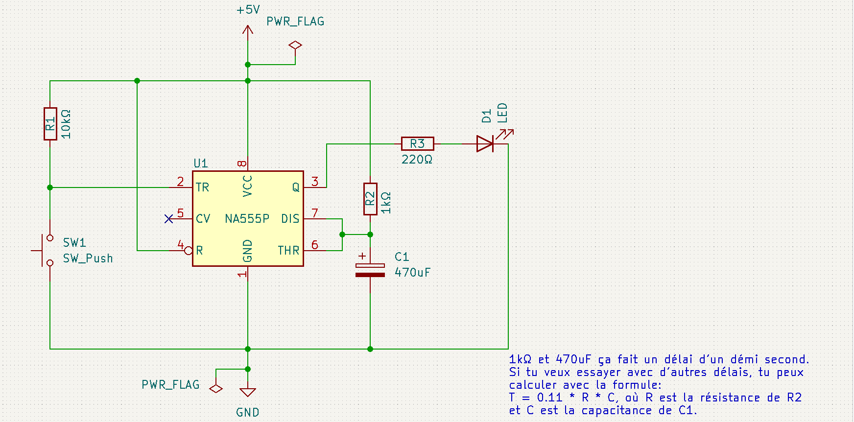
| Qty | Value | Footprint | References |
|---|---|---|---|
| 1 | 10kΩ | Resistor_THT:R_Axial_DIN0207_L6.3mm_D2.5mm_P7.62mm_Horizontal | R1 |
| 1 | 1kΩ | Resistor_THT:R_Axial_DIN0207_L6.3mm_D2.5mm_P7.62mm_Horizontal | R2 |
| 1 | 220Ω | Resistor_THT:R_Axial_DIN0207_L6.3mm_D2.5mm_P7.62mm_Horizontal | R3 |
| 1 | 470uF | Capacitor_THT:CP_Radial_D10.0mm_P2.50mm | C1 |
| 1 | LED | LED_THT:LED_D3.0mm_Clear | D1 |
| 1 | NA555P | Package_SO:SOIC-8_3.9x4.9mm_P1.27mm | U1 |
| 1 | SW_Push | Button_Switch_THT:SW_Tactile_Straight_KSL0Axx1LFTR | SW1 |
torjc01/CircuitosEletronicos
Repositorio de projetos de circuitos eletronicos e de design blocks, nos CADS Eagle e Kicad6.

torjc01/CircuitosEletronicos
Repositorio de projetos de circuitos eletronicos e de design blocks, nos CADS Eagle e Kicad6.

torjc01/CircuitosEletronicos
Repositorio de projetos de circuitos eletronicos e de design blocks, nos CADS Eagle e Kicad6.

gajdi88/M-NET-Thermostat
Smart thermostat for Mitsubishi's M-NET communication protocol

KhushiShah63/DC-Motor-Speed-Controller-
A 555 timer–based DC motor speed controller designed to control the speed of a DC motor using PWM (Pulse Width Modulation).

Nik-Sch/EDiC
Developement, Simulation and Emulation of an 8 bit CPU including a Software Framework for my Masters Thesis


GokulS20G/queaky-stem-toy-pcb
PCB design of a Queaky Stem Toy using KiCad with schematic, layout, and Gerber files.

It measures 32.8 × 25.8 mm and has 2 copper layers, 1.6 mm thick.
7 parts, built around the NA555P. The full list of its parts is on this page, with links to each part's symbol and footprint where PCBKit's library has them.
From the torjc01/CircuitosEletronicos repository on GitHub, at the commit this page was made from: the board is Kicad6/TimerOff/TimerOff.kicad_pcb and its schematic Kicad6/Arduminimum/Arduminimum.kicad_sch. PCBKit opens the board in the browser, with nothing to install.
Its repository states no licence, so its author keeps all rights: ask torjc01 before reusing the design.