2 layers100 × 45 mm

 tomarus/midi2cv31
Eurorack MIDI2CV and Arpeggiator using an Arduino Nano.
Midi2cv is an open-source printed circuit board by tomarus, from the tomarus/midi2cv repository on GitHub. It is a 2-layer board of 81.3 × 96.5 mm with 63 parts on 112 nets, routed with 544 tracks and 22 vias.
It is built around the MCP4922-E/P, 24LC256-I/P and 74HC595, with the L7805 and B10K among its other parts. Its parts include 25 connectors, 15 resistors, 9 capacitors, 8 ICs and 4 diodes. It belongs with the audio and music boards and the AVR (ATmega, ATtiny) boards of this library.


Miarph is an Arduino based MIDI2CV converter with 4 0-5V 12 bit DAC's and 10 trigger outputs.
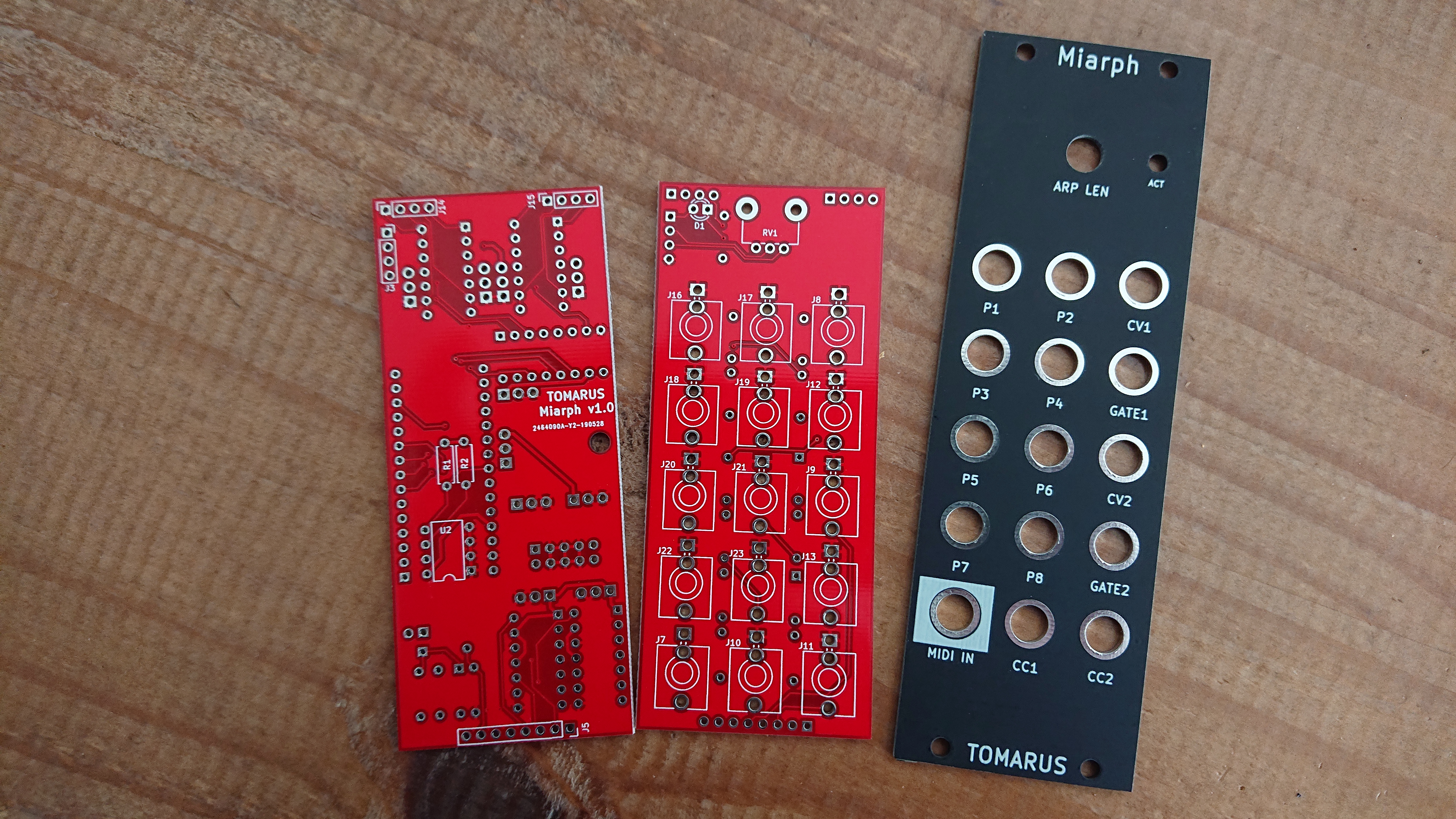
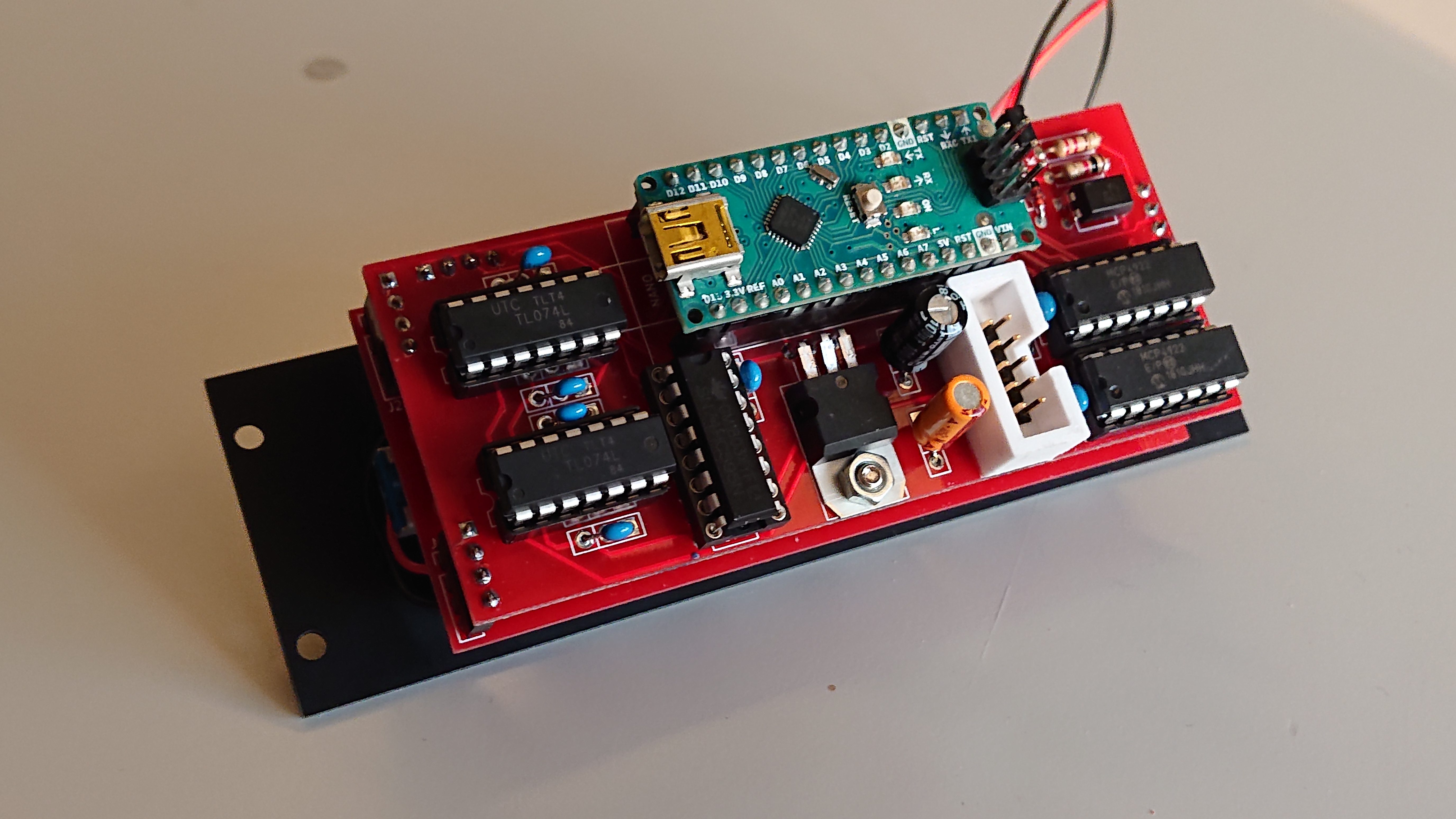


See https://midi.tomarus.io/miarph/
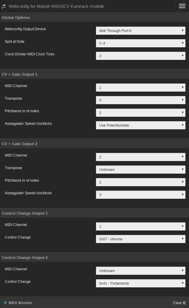
You need a modern browser like Opera or Chrome to use this site.
Note that all values are initially unknown until you actually change something. The device has no MIDI output so config values can't be read back.
After initially building the device, you should set all of your defaults once via webconfig. After changing values it is stored on the device's eeprom and used at the next power up.
Use the midi2cv Go utility to program the device.
Example:
./midi2cv write 0x01 0x77
Where 0x01 is the address and 0x77 the value.
List of addresses to program:
| Address | Description | Example value |
|---|---|---|
| 0x00 | unused | -- |
| 0x01 | Split keyboard at note | 0x40 (use 0x00 for no split) |
| 0x02 | MIDI 1 Channel | 0x01 |
| 0x03 | MIDI 2 Channel | 0x02 |
| 0x04 | Transpose Channel 1 | 0x40 |
| 0x05 | Transpose Channel 2 | 0x40 |
| 0x06 | Control Change Number Channel 1 | 0x07 (0x07 = volume) |
| 0x07 | Control Change Number Channel 2 | 0x6A (0x6A = filter cutoff) |
| 0x08 | Control Change Channel 1 | 0x01 |
| 0x09 | Control Change Channel 2 | 0x02 |
| 0x0a | Pitchbend Channel 1 | 0x02 (number of notes) |
| 0x0b | Pitchbend Channel 2 | 0x0c (number of notes) |
| 0x0c | Midi Channel 1 sync | 0x00 (00 = use potmeter, otherwise nr of midi clock ticks) |
| 0x0d | Midi Channel 2 sync | 0x00 (00 = use potmeter, otherwise nr of midi clock ticks) |
| 0x0e | Clockticks to advance the clock divider | 0x03 (0x03 = sync to quarter notes) |
| 0x0f | unused | -- |
| 0x10..0x18 | Port Mode (0 = clock divider, 1 = drum trigger) | 0x00 |
| 0x18..0x20 | Port Trigger Note | 0x36 |
| 0x20..0x28 | Port Clock Divider Division (0=1/1, 1=1/2, 2=1/4, 3=1/8, etc) | 0x00 |
| Designator | Package | Quantity | Designation | PartNo |
|---|---|---|---|---|
| RV1 | Potentiometer_Alps_RK09K_Single_Vertical | 1 | B10K | |
| NANO | Arduino_Nano_Silk | 1 | Nano v3 | |
| C1 | GenericCap | 1 | 100uF | |
| C2 | GenericCap | 1 | 10uF | |
| C3,C4,C5,C6,C7,C8,C9 | GenericCap | 7 | 100nF | |
| D1 | LED_D3.0mm | 1 | LED | |
| D2,D3,D4 | D_DO-35_SOD27_P7.62mm_Horizontal | 3 | D | |
| J1 | PinHeader_1x02_P2.54mm_Vertical | 1 | ProgramJmpr | |
| J2 | IDC-Header_2x05_P2.54mm_Vertical | 1 | Power | |
| J3,J14,J15 | PinSocket_1x04_P2.54mm_Vertical | 3 | Conn_01x04_M | |
| J4,J24,J25 | PinHeader_1x04_P2.54mm_Vertical | 3 | Conn_01x04_F | |
| J5 | PinSocket_1x08_P2.54mm_Vertical | 1 | Conn_01x08_M | |
| J6 | PinHeader_1x08_P2.54mm_Vertical | 1 | Conn_01x08_F | |
| J7 | Jack_3.5mm_QingPu_WQP-PJ366ST_Vertical | 1 | Midi Input | |
| J8-J13,J16-J23 | Jack_3.5mm_QingPu_WQP-PJ398SM_Vertical | 14 | Misc | |
| R1,R2 | R_Axial_DIN0207_L6.3mm_D2.5mm_P7.62mm | 2 | 2K2 | |
| R3,R4,R5,R6 | R_Axial_DIN0207_L6.3mm_D2.5mm_P7.62mm | 4 | 1K | |
| R7 | R_Axial_DIN0207_L6.3mm_D2.5mm_P7.62mm | 1 | 220 | |
| R8,R9,R10,R11,R12,R13,R14,R15 | R_Axial_DIN0207_L6.3mm_D2.5mm_P7.62mm | 8 | 100 | |
| U1 | TO-220-3_Horizontal_TabDown | 1 | L7805 | |
| U2 | DIP-8_W7.62mm | 1 | 24LC256 | |
| U5 | DIP-4_W7.62mm | 1 | PC817 | PC817XNNSZ1B |
| U6,U8 | DIP-14_W7.62mm | 2 | TL074 | |
| U7 | DIP-16_W7.62mm | 1 | 74HC595 | |
| U3,U4 | DIP-14_W7.62mm | 2 | MCP4922 |
| Qty | Value | Footprint | References |
|---|---|---|---|
| 8 | 100 | Resistor_THT:R_Axial_DIN0207_L6.3mm_D2.5mm_P7.62mm_Horizontal | R8, R9, R10, R11, R12, R13, R14, R15 |
| 7 | 100nF | Tomarus:GenericCap | C3, C4, C5, C6, C7, C8, C9 |
| 3 | 1K | Resistor_THT:R_Axial_DIN0207_L6.3mm_D2.5mm_P7.62mm_Horizontal | R4, R5, R6 |
| 3 | Conn_01x04_Female | Connector_PinHeader_2.54mm:PinHeader_1x04_P2.54mm_Vertical | J4, J24, J25 |
| 3 | Conn_01x04_Male | Connector_PinSocket_2.54mm:PinSocket_1x04_P2.54mm_Vertical | J3, J14, J15 |
| 3 | D | Diode_THT:D_DO-35_SOD27_P7.62mm_Horizontal | D2, D3, D4 |
| 2 | 2K2 | Resistor_THT:R_Axial_DIN0207_L6.3mm_D2.5mm_P7.62mm_Horizontal | R1, R2 |
| 2 | MCP4922 | Package_DIP:DIP-14_W7.62mm | U3, U4 |
| 2 | TL074 | Package_DIP:DIP-14_W7.62mm | U6, U8 |
| 1 | 100uF | Tomarus:GenericCap | C1 |
| 1 | 10K | Resistor_THT:R_Axial_DIN0207_L6.3mm_D2.5mm_P7.62mm_Horizontal | R3 |
| 1 | 10uF | Tomarus:GenericCap | C2 |
| 1 | 220/470 | Resistor_THT:R_Axial_DIN0207_L6.3mm_D2.5mm_P7.62mm_Horizontal | R7 |
| 1 | 24LC256 | Package_DIP:DIP-8_W7.62mm | U2 |
| 1 | 74HC595 | Package_DIP:DIP-16_W7.62mm | U7 |
| 1 | Arduino_Nano_v3.x | Tomarus:Arduino_Nano_Silk | A1 |
| 1 | B10K | Tomarus:Potentiometer_Alps_RK09K_Single_Vertical_HalfSilk | RV1 |
| 1 | CTL1 Output | Connector_Audio:Jack_3.5mm_QingPu_WQP-PJ398SM_Vertical_CircularHoles | J10 |
| 1 | CTL2 Output | Connector_Audio:Jack_3.5mm_QingPu_WQP-PJ398SM_Vertical_CircularHoles | J11 |
| 1 | CV1 Output | Connector_Audio:Jack_3.5mm_QingPu_WQP-PJ398SM_Vertical_CircularHoles | J8 |
| 1 | CV2 Output | Connector_Audio:Jack_3.5mm_QingPu_WQP-PJ398SM_Vertical_CircularHoles | J9 |
| 1 | Conn_01x08_Female | Connector_PinHeader_2.54mm:PinHeader_1x08_P2.54mm_Vertical | J6 |
| 1 | Conn_01x08_Male | Connector_PinSocket_2.54mm:PinSocket_1x08_P2.54mm_Vertical | J5 |
| 1 | Gate1 Output | Connector_Audio:Jack_3.5mm_QingPu_WQP-PJ398SM_Vertical_CircularHoles | J12 |
| 1 | Gate2 Output | Connector_Audio:Jack_3.5mm_QingPu_WQP-PJ398SM_Vertical_CircularHoles | J13 |
| 1 | L7805 | Package_TO_SOT_THT:TO-220-3_Horizontal_TabDown | U1 |
| 1 | LED | LED_THT:LED_D3.0mm | D1 |
| 1 | Midi Input | Tomarus:Jack_3.5mm_QingPu_WQP-PJ366ST_Vertical_CircularHoles | J7 |
| 1 | P1 | Connector_Audio:Jack_3.5mm_QingPu_WQP-PJ398SM_Vertical_CircularHoles | J16 |
| 1 | P2 | Connector_Audio:Jack_3.5mm_QingPu_WQP-PJ398SM_Vertical_CircularHoles | J17 |
| 1 | P3 | Connector_Audio:Jack_3.5mm_QingPu_WQP-PJ398SM_Vertical_CircularHoles | J18 |
| 1 | P4 | Connector_Audio:Jack_3.5mm_QingPu_WQP-PJ398SM_Vertical_CircularHoles | J19 |
| 1 | P5 | Connector_Audio:Jack_3.5mm_QingPu_WQP-PJ398SM_Vertical_CircularHoles | J20 |
| 1 | P6 | Connector_Audio:Jack_3.5mm_QingPu_WQP-PJ398SM_Vertical_CircularHoles | J21 |
| 1 | P7 | Connector_Audio:Jack_3.5mm_QingPu_WQP-PJ398SM_Vertical_CircularHoles | J22 |
| 1 | P8 | Connector_Audio:Jack_3.5mm_QingPu_WQP-PJ398SM_Vertical_CircularHoles | J23 |
| 1 | PC817 | Package_DIP:DIP-4_W7.62mm | U5 |
| 1 | Power | Connector_IDC:IDC-Header_2x05_P2.54mm_Vertical | J2 |
| 1 | ProgramJmpr | Connector_PinHeader_2.54mm:PinHeader_1x02_P2.54mm_Vertical | J1 |
It measures 81.3 × 96.5 mm and has 2 copper layers, 1.6 mm thick.
63 parts, built around the MCP4922-E/P, 24LC256-I/P, 74HC595 and L7805. The full list of its parts is on this page, with links to each part's symbol and footprint where PCBKit's library has them.
From the tomarus/midi2cv repository on GitHub, at the commit this page was made from: the board is kicad/midi2cv/midi2cv.kicad_pcb. PCBKit opens the board in the browser, with nothing to install.
Its repository states no licence, so its author keeps all rights: ask tomarus before reusing the design.


stevieb9/rpi-wiringpi
Perl interface to Raspberry Pi's board, GPIO and various sensors and ICs


Sakib-Ansari/Linear_Programmable_Power_Supply
This repository contains the complete KiCad project for a multi-board linear programmable bench power supply. The design is organized into separate PCBs, including the Power Board, Control Board, Front Panel, Output…


zlosynth/arplus
Quantizer, arpeggiator, and string synthesizer in a single module.