
2 layers78 × 60 mm

 tom01h/RA4M11
Arduino UNO R4もどき
Adruino 0 is an open-source printed circuit board by tom01h, from the tom01h/RA4M1 repository on GitHub. It is a 2-layer board of 67.1 × 62.7 mm with 21 parts on 49 nets, routed with 293 tracks and 9 vias.
It is built around the W25Q32JVSSIQ. Its parts include 16 connectors, 3 resistors and 1 IC.
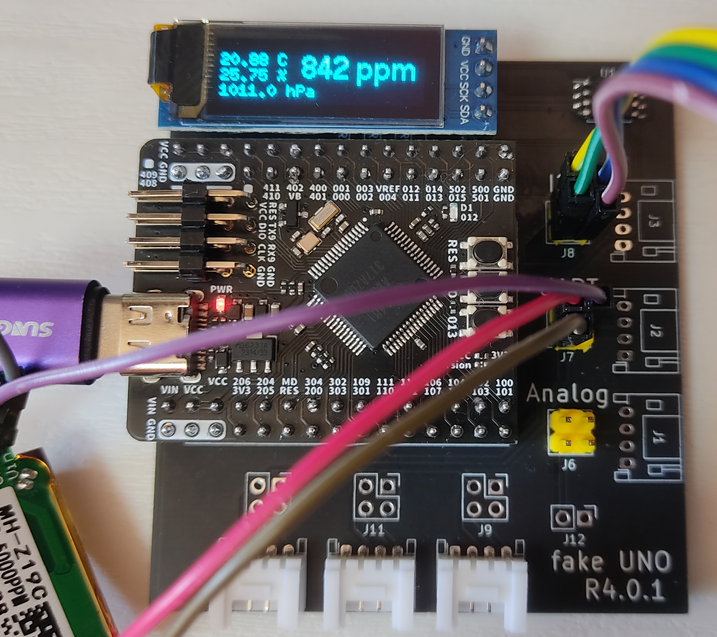
BME280とMH-Z19をつないで温度・湿度・気圧と二酸化炭素濃度を表示する
5V電源がないので外部から持ってくる(GNDに注意!!)
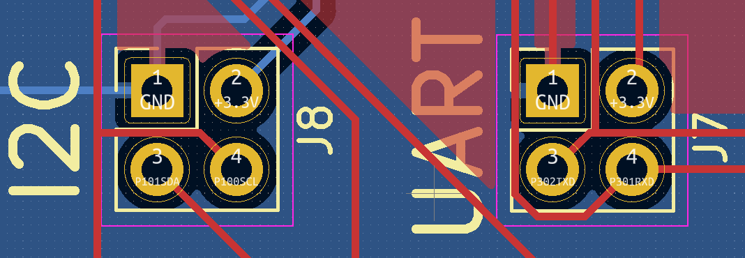
RTC電池を使って時計を動かす(純正のR4 Minimaには電池繋げません)
電池ホルターはこれ
| Qty | Value | Footprint | References |
|---|---|---|---|
| 6 | Conn_01x04_Male | Connector_JST:JST_PH_S4B-PH-K_1x04_P2.00mm_Horizontal | J1, J2, J3, J5, J10, J15 |
| 5 | Conn_02x02_Odd_Even | Connector_PinHeader_2.54mm:PinHeader_2x02_P2.54mm_Vertical | J7, J8, J9, J11, J16 |
| 3 | R | Resistor_SMD:R_1206_3216Metric_Pad1.30x1.75mm_HandSolder | R1, R2, R3 |
| 2 | Conn_02x15_Odd_Even | Connector_PinHeader_2.54mm:PinHeader_2x15_P2.54mm_Vertical | J13, J14 |
| 1 | Battery_Cell | My:CH291-1220LF | BT1 |
| 1 | Conn_01x02_Male | Connector_PinHeader_2.54mm:PinHeader_1x02_P2.54mm_Vertical | J12 |
| 1 | W25Q32JVSS | Package_SO:SOIC-8_5.23x5.23mm_P1.27mm | U1 |
| 1 | locked | Connector_PinHeader_2.54mm:PinHeader_1x04_P2.54mm_Vertical | J4 |
| 1 | locked | Connector_PinHeader_2.54mm:PinHeader_2x02_P2.54mm_Vertical | J6 |

plinkysynth/plinky_public
a public release of the plinky sw and hw


murexrobotics/electrical
Highly integrated electronics design and printed circuit boards (PCBs) for the MATE ROV Competition. Attempt the impossible.


KaiPereira/Overglade-Badges
NFC hackathon badges for the Overglade game jam in Singapore!

efabless/foss-asic-tools
FOSS-ASIC-TOOLS is all in one container for SKY130 based design both Analog and Digital. Below is a list of the current tools already installed and ready to use.

NikodemBartnik/StarTrckr
Open source star tracker for deep sky astrophotography
It measures 67.1 × 62.7 mm and has 2 copper layers, 1.6 mm thick.
21 parts, built around the W25Q32JVSSIQ. The full list of its parts is on this page, with links to each part's symbol and footprint where PCBKit's library has them.
From the tom01h/RA4M1 repository on GitHub, at the commit this page was made from: the board is adruino_0.kicad_pcb and its schematic adruino_0.kicad_sch. PCBKit opens the board in the browser, with nothing to install.
Its repository states no licence, so its author keeps all rights: ask tom01h before reusing the design.