2 layers139.7 × 73.7 mm

 TKontu/ltc4368-2s-protector
An inline protection board for replacing 2S NiMH/NiCd packs with 2S LiPo/LiHV, built around the Analog Devices LTC4368-1. NiMH tolerates being run flat; LiPo/LiHV does not.
DC2418A-2 is an open-source printed circuit board by TKontu, from the TKontu/ltc4368-2s-protector repository on GitHub, published under the CERN-OHL-S-2.0 licence. It is a 2-layer board of 61.2 × 34.1 mm with 40 parts on 12 nets, routed with 61 tracks and 18 vias.
Its parts include 9 capacitors, 7 resistors, 2 transistors and 1 IC.
An inline protection board for replacing 2S NiMH/NiCd packs with 2S LiPo/LiHV, built around the Analog Devices LTC4368-1. NiMH tolerates being run flat; LiPo/LiHV does not. This board adds the low-voltage cutoff those older packs never needed, plus reverse-battery and bidirectional overcurrent protection, between the battery and the existing load.
Pack-total sensing on the two main leads only — cell balancing is handled by the charger via the balance lead. Adapted from the ADI DC2418A demo board, rescaled from 24 V / 10 A to a 2S (6.0–8.7 V) pack.
Status: built and bench-tested (smoke-stopper current-limited first power-up) on the current revision.
| Front (F.Cu) | Back (B.Cu) |
|---|---|
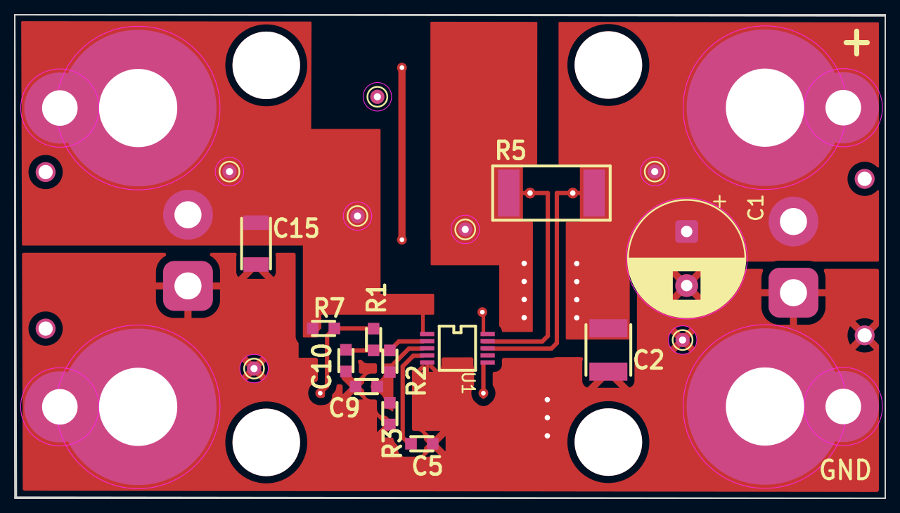 | 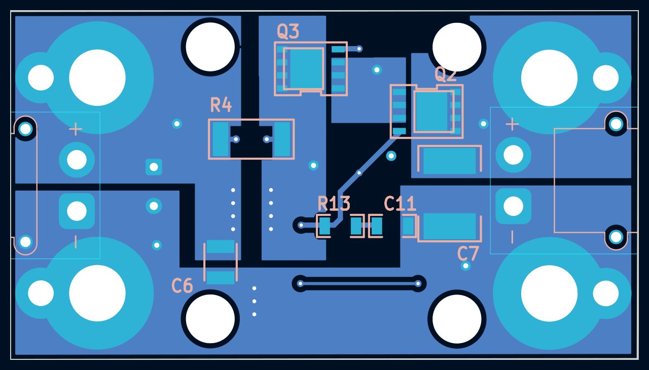 |
Board outline 60.0 × 33.5 mm, 2 layers, XT30PW-M (VIN) and XT30PW-F (VOUT) horizontal connectors, 4× M5.5 mounting holes.
| Parameter | Value | Set by |
|---|---|---|
| Battery | 2S LiPo / LiHV (7.4 / 7.6 V nom) | — |
| Input range | 6.0 – 8.7 V (chip: 2.5–60 V) | — |
| Under-voltage cutoff | 6.36 V (3.18 V/cell) under load | R7/R1/R2/R3 |
| Over-voltage cutoff | ~9.9 V | R7/R1/R2/R3 |
| Overcurrent trip | ~42 A fwd & rev | R4 = 1.2 mΩ |
| OC response | Auto-retry (~1.3 s) | C5 = 0.22 µF |
| Quiescent | ~4–10 µA (op), <3 µA (shutdown) | — |
Thresholds are ratios against the LTC4368's 0.5 V references, so only ratios matter:
V_UV   = 0.5 x (R7+R1+R2+R3) / (R2+R3)   -> 6.36 V
V_OV   = 0.5 x (R7+R1+R2+R3) / R3        -> 9.9 V
I_trip = 0.050 / R4                       -> ~42 A at 1.2 mohm
For 3.0 V/cell set V_UV = 6.0 V; for a different breaker point R4 = 0.050 / I_trip.
DC2418-LVC-end/             KiCad project + Gerbers; XT30 connectors at the board ends
  DC2418A-2.kicad_sch / .kicad_pcb / .kicad_pro
  DC2418A-2-*.gbr / *.drl / *-job.gbrjob    Fabrication outputs (Gerber X2 + Excellon)
DC2418-LVC-side/            Electrically identical; XT30 connectors to the side
  LVC.kicad_sch / .kicad_pcb / .kicad_pro
  LVC-*.gbr / *.drl / *-job.gbrjob          Fabrication outputs
BOM.csv                     LCSC-referenced bill of materials
front.png / back.png Layout views of DC2418-LVC-end| Ref | Value / Part | Package | Notes |
|---|---|---|---|
| U1 | LTC4368CMS-1 | MSOP-10 | Use I-grade (LTC4368IMS-1) for sub-zero use |
| Q2, Q3 | SiR870ADP (or IRLR7843 in DPAK) | PDFN-8 5×6 | Back-to-back N-FETs; PDFN has a thermal pad |
| R4 | 1.2 mΩ ≥1 W, alloy/current-sense | 2512 | Overcurrent set point — must be a metal-element part |
| R7 | 649 kΩ 1% | 0603 | Divider (SHDN tap) |
| R1 | 1.18 MΩ 1% | 0603 | Divider (UV tap) |
| R2 | 56.2 kΩ 1% | 0603 | Divider (OV tap) |
| R3 | 100 kΩ 1% | 0603 | Divider (bottom) |
| R13 | 22 kΩ | 1206 | Gate inrush resistor |
| C11 | 3.3 nF | 1206 | Gate inrush cap (soft-start) |
| C5 | 0.22 µF | 0603 | RETRY → auto-retry (GND = latch-off) |
| C15 | 1 µF | 1206 | VIN bypass (place at the pin) |
| C7 | 4.7 µF (optional) | 2220 | Input bulk cap |
| C1 | 47 µF ≥25 V | THT radial, D8.0 mm body / 3.5 mm pitch | Output bulk cap — footprint is CP_Radial_D8.0mm_P3.80mm |
| C2, C6 | 4.7 µF | 1210 | Output caps |
Divider values are E96 1%. Cap voltage ratings are inherited 100 V parts; 25 V is sufficient for a 2S pack.
Not in the BOM: the XT30 connectors are not listed — both boards place an
AMASS_XT30PW-M(VIN) and anAMASS_XT30PW-F(VOUT), source them separately. The bidirectional TVS recommended under Usage is also not listed.Do not populate: R5 (2512) — the DC2418A's version-option pair with R4. On the -A build, R4 is the live sense position (1.2 mΩ); R5 is the -B's 0.02 Ω slot. Verified: R4 and R5 bridge the same two nodes (
VOUT↔Net-(U1-SENSE)), i.e. parallel alternates, not in series — so leaving R5 empty is harmless. AlsoC9andC10, both markedOPT.
Discharge-side protection only. LiPo/LiHV is hazardous if abused — charge on a proper balance charger in a fireproof location, never unattended. Provided as-is, without warranty; verify in your own application.
Topology adapted from Analog Devices' DC2418A demo board for the LTC4368; independently re-drawn schematic and layout, not affiliated with or endorsed by ADI.
Hardware (schematics, layout, Gerbers): CERN-OHL-S-2.0 — strongly reciprocal. Documentation (this README, BOM, images): CC-BY-4.0.
| Qty | Value | Footprint | References |
|---|---|---|---|
| 4 | KEYSTONE_8831 | KEYSTONE_8831 | MH3, MH4, MH5, MH6 |
| 3 | OPT | 0603 | C5, C9, C10 |
| 2 | 4.7 uF | 1210 | C2, C6 |
| 2 | SIR870ADP-T1-GE3 | MOSFET-SO8-PWRPAK-SINGLE | Q2, Q3 |
| 1 | 1 uF | CC1206N | C15 |
| 1 | 1.18 M | 0603 | R1 |
| 1 | 1.2 m | 2512 | R4 |
| 1 | 100 k | 0603 | R3 |
| 1 | 22 k | 1206 | R13 |
| 1 | 3.3 nF | 1206 | C11 |
| 1 | 4.7 uF | 2220 | C7 |
| 1 | 47 uF | Capacitor_THT:CP_Radial_D8.0mm_P3.80mm | C1 |
| 1 | 56.2 k | 0603 | R2 |
| 1 | 649 k | 0603 | R7 |
| 1 | DNP | 2512 | R5 |
| 1 | LTC4368IMS-1_PBF | MS10 | U1 |
The 23 most common of 40 parts.
It measures 61.2 × 34.1 mm and has 2 copper layers, 1.6 mm thick.
40 parts. The full list of its parts is on this page, with links to each part's symbol and footprint where PCBKit's library has them.
From the TKontu/ltc4368-2s-protector repository on GitHub, at the commit this page was made from: the board is DC2418-LVC-end/DC2418A-2.kicad_pcb and its schematic DC2418-LVC-end/DC2418A-2.kicad_sch. PCBKit opens the board in the browser, with nothing to install.
Its repository publishes it under the CERN-OHL-S-2.0 licence: you may reuse it on that licence's terms (keep the author's notice, and for a copyleft licence share your changes alike).

hackclub/OnBoard
💡 Join 1,000 teenagers and make your first PCB with a $100 grant!

Chrismettal/EleLab_v2
Cheap DIY lab system for hobbyists and the tinkering folk

Chrismettal/flipper-zero-backpacks
Backpack-style addon boards for the Flipper Zero!


ohmtech-rdi/eurorack-blocks
Software to Hardware Prototyping for Eurorack using C++, Max/Gen~ or Faust
