Skip to the content
PCBKitNew board
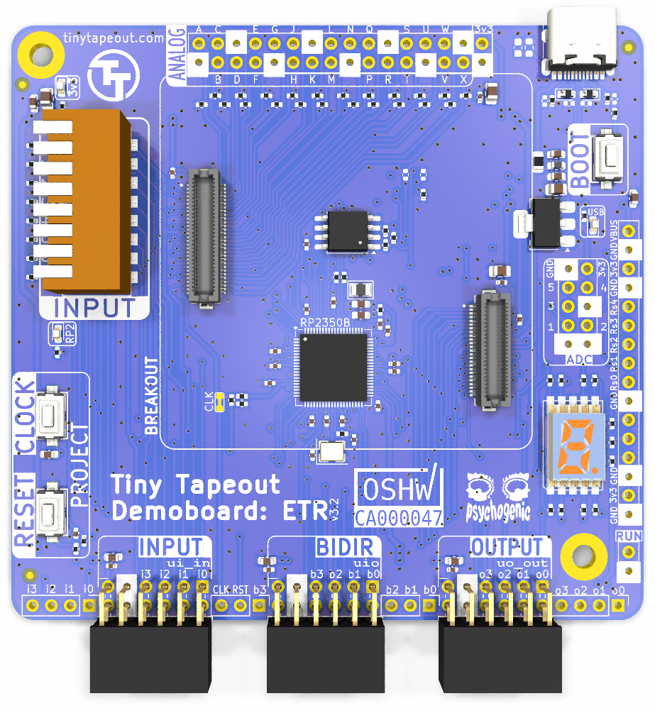
4 layers85 × 85 mmTinytapeout demo, the printed circuit board in 3D

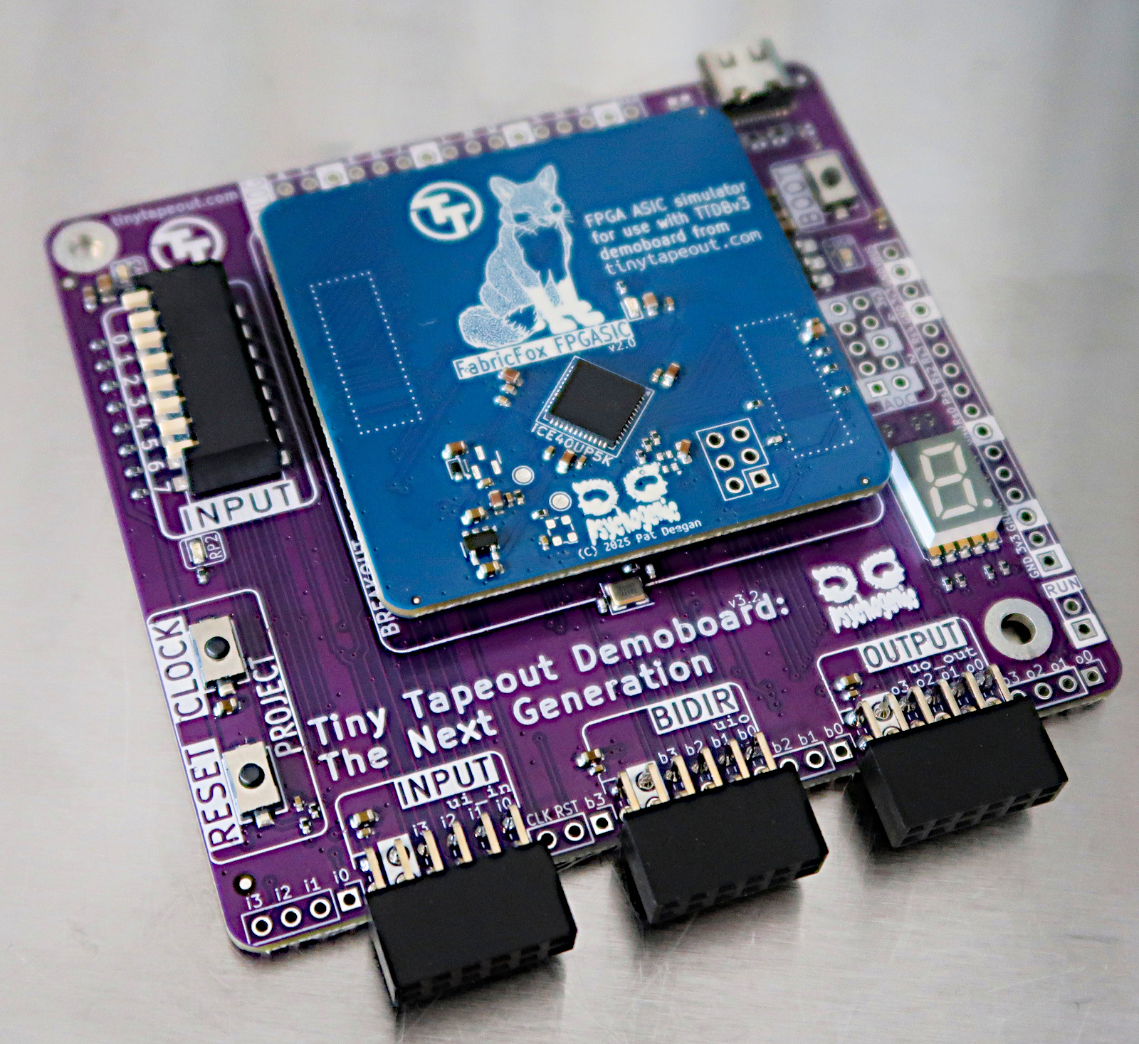
Demo board for TT04 and beyond

Size
85 × 85 mm
Copper layers
4
Thickness
1.56 mm
Parts
330
Nets
148
Pads
877
Tracks, vias
2,785, 401
Pours
7
Routed
Yes
KiCad
KiCad 9.0 (file 20241229)
Created
11 Oct 2023
Updated
29 Aug 2026

Overview

Tinytapeout demo is an open-source printed circuit board by TinyTapeout, from the TinyTapeout/tt-demo-pcb repository on GitHub, published under the Apache-2.0 licence. It is a 4-layer board of 85 × 85 mm with 330 parts on 148 nets, routed with 2,785 tracks and 401 vias.

It is built around the RP2350B, MCP6001UT-I/OT-HX and W25Q32JVSSIQ, with the NC7SV14P5X, TLV1117LV33DCYR and SP3022-01ETG-MS among its other parts. Its parts include 47 capacitors, 45 resistors, 27 diodes, 16 connectors and 7 ICs. It belongs with the RP2350 boards of this library.

Main components

12

README

README.md

Tiny Tapeout Demo Board

Demo board for Tiny Tapeout ASICs

Demoboard PCB

These demonstration PCBs allow you to interact with Tiny Tapeout projects in 3 ways:

  • directly, using the input DIP switches and 7-segment display;
  • via breadboard or extension boards through PMODs; or
  • by interacting through the on-board RP2

Demoboard PCB

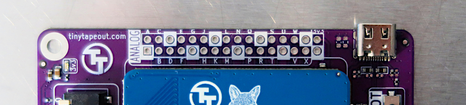
In addition, since TT06, it is possible to create analog and mixed signal designs. These signals are now available on a 100mil header directly on the demoboard

Breakout Board Analog IO

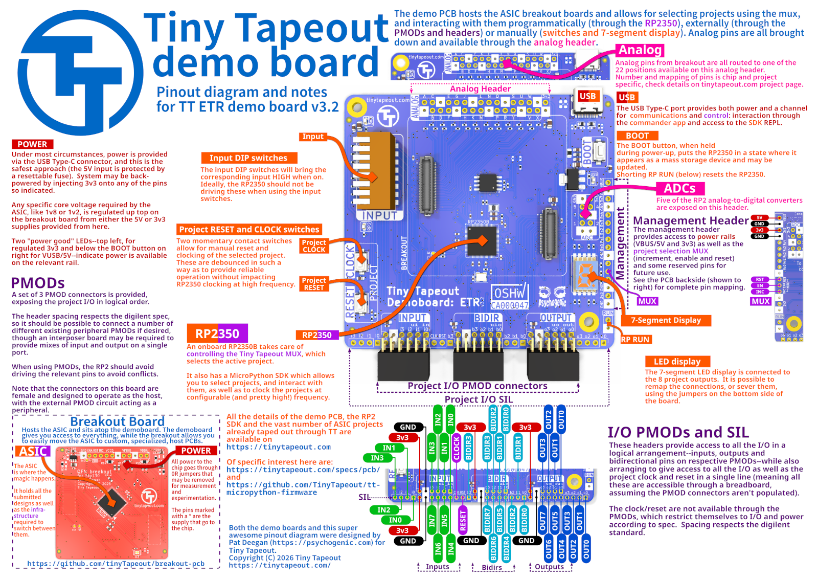
Pinout Overview

Demoboard Pinout

Previous Demoboard Versions

The details above are for the latest version of the demoboard. To access leaflets and schematics for prior versions, see here, in the historic documentation

Schematic and Function

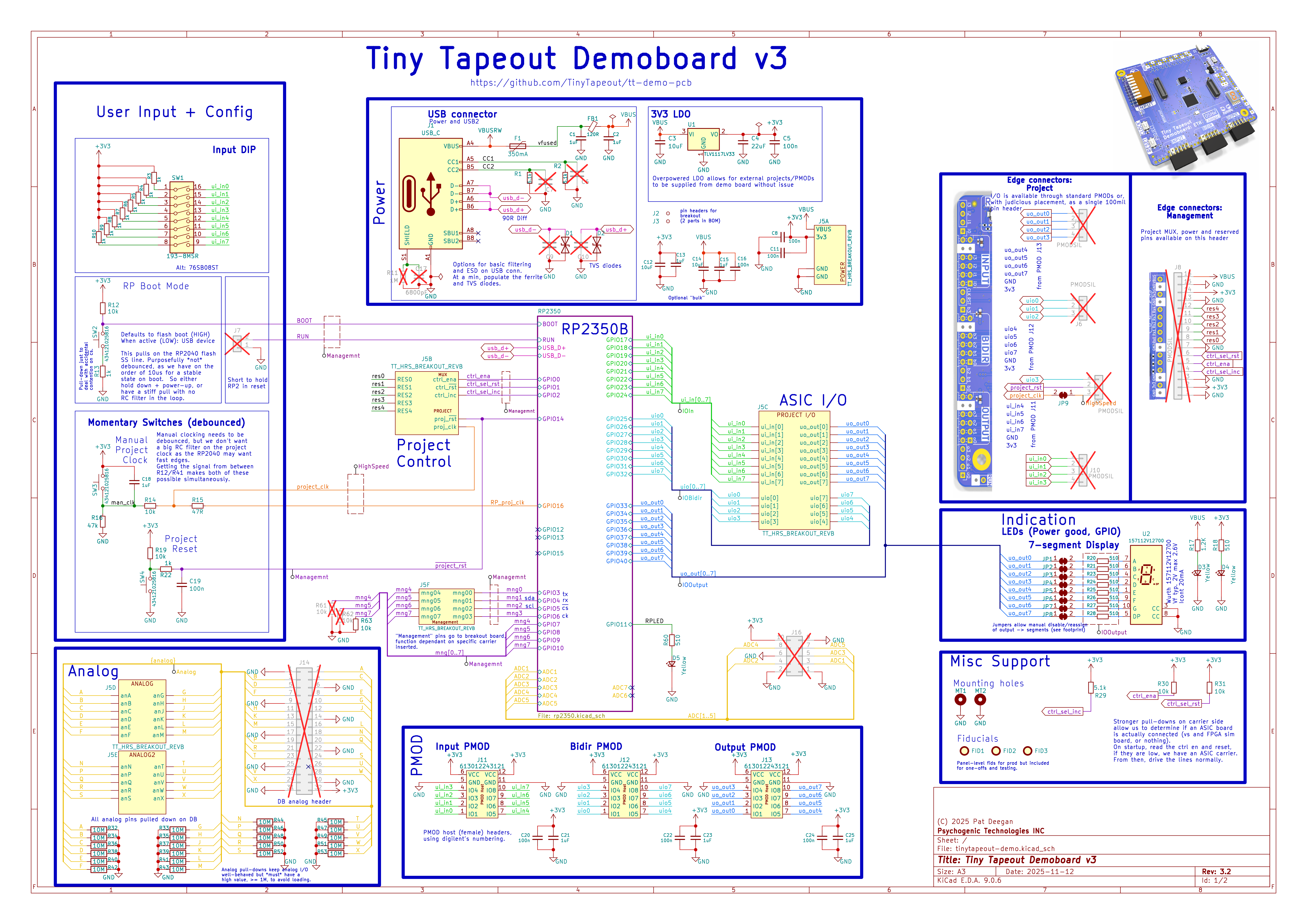
The full schematic is available as a PDF but the gist of it is:

Demoboard schematic

The RP2350 is responsible for selecting projects, by controlling the project MUX that's on the ASIC and, under most circumstances, providing the clock for the projects. It may, thereafter, interact with the design via it's connections to the input, output and bidirectional pins.

Another option is to use the various PMOD and pin headers to tie external circuitry to the design. PMODs are provided in two varieties: straightforward I/O (where one PMOD is dedicated to each of in/out/bidir pins) and "standard" PMODs, that are mapped (mostly) according to specs to allow for SPI, I2C and UART extension boards to be plugged in (this assumes the project has been designed with this in mind, with I/O tasked accordingly).

PMODs

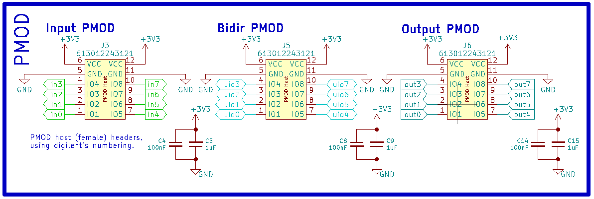
In addition with interfacing directly with projects via the RP2, extensions and interaction with the ASIC is possible through two sets of PMODs on the demo boards.

The three on the bottom provide access to all the project I/O in a logical fashion, with inputs, bidirectional pins and outputs available on their own distinct headers.

IO PMODs

This is nice and orderly and gives you access to all the pins, but extension boards will often need to span at least two, and sometimes three, distinct headers.

For interfacing peripheral modules, an interposer board was created (TODO: display and link) to provide more standard mixes of input and output on single PMODs.

RP2 Pinout

TT PinRP2 PinI2CSPIUART
resetGPIO14
clockGPIO16
ui_in[0]GPIO17SPI0.cs
ui_in[1]GPIO18SPI0.sck
ui_in[2]GPIO19SPI0.tx
ui_in[3]GPIO20UART1.tx
ui_in[4]GPIO21SPI0.cs
ui_in[5]GPIO22SPI0.sck
ui_in[6]GPIO23SPI0.txUART1.rts
ui_in[7]GPIO24
uio[0]GPIO25I2C0.sclSPI1.csUART1.rx
uio[1]GPIO26I2C1.sdaSPI1.sckUART1.cts
uio[2]GPIO27I2C1.sclSPI1.txUART0.rts
uio[3]GPIO28I2C0.sdaSPI1.rxUART0.tx
uio[4]GPIO29I2C0.sclSPI1.csUART0.rx
uio[5]GPIO30I2C1.sdaSPI1.sckUART0.cts
uio[6]GPIO31I2C1.sclSPI1.txUART0.rts
uio[7]GPIO32
uo_out[0]GPIO33UART0.rx
uo_out[1]GPIO34UART0.cts
uo_out[2]GPIO35
uo_out[3]GPIO36SPI0.rx
uo_out[4]GPIO37UART1.rx
uo_out[5]GPIO38UART1.cts
uo_out[6]GPIO39
uo_out[7]GPIO40SPI0.rx

Removing the ASIC breakout board

With the Hirose DF12 Series connectors now in use, removing breakouts from demoboards should be much more straightforward:

  • Insert a finger on opposite diagonals (top left, bottom right)
  • Gently pry upwards until the breakout pops off.

There are markings indicating where the actually connectors are placed, on the underside, on the breakouts.

License

Parts

330
QtyValueFootprintReferences
134StitchingVia-0.4mmDrillflyingcarsfootprints:StitchingVia-0.4mmDrillSTITCH01, STITCH01, STITCH01, STITCH01, STITCH01, STITCH01, STITCH01, STITCH01, STITCH01, STITCH01, STITCH01, STITCH01, STITCH01, STITCH01, STITCH01, STITCH01 +118
26StitchingVia-0.3mmflyingcarsfootprints:StitchingVia-0.3mmSTITCHSM01, STITCHSM01, STITCHSM01, STITCHSM01, STITCHSM01, STITCHSM01, STITCHSM01, STITCHSM01, STITCHSM01, STITCHSM01, STITCHSM01, STITCHSM01, STITCHSM01, STITCHSM01, STITCHSM01, STITCHSM01 +10
22100nCapacitor_SMD:C_0402_1005MetricC11, C16, C18, C20, C21, C24, C26, C28, C31, C33, C35, C36, C37, C38, C39, C40 +6
225VTVSDiode_SMD:D_SOD-882D10, D11, D12, D13, D14, D15, D16, D17, D18, D19, D20, D21, D22, D23, D24, D25 +6
131kResistor_SMD:R_0402_1005MetricR1, R4, R5, R6, R7, R8, R9, R10, R13, R15, R22, R23, R43
1210kResistor_SMD:R_0402_1005MetricR12, R14, R25, R27, R29, R31, R33, R34, R35, R38, R39, R42
101uFCapacitor_SMD:C_0603_1608MetricC1, C2, C13, C15, C19, C22, C23, C25, C27, C29
10510Resistor_SMD:R_0402_1005MetricR18, R19, R20, R21, R24, R26, R28, R30, R32, R36
9SolderJumper_2_BridgedTinyTapeout:SolderJumper-2_0603JP1, JP2, JP3, JP4, JP5, JP6, JP7, JP8, JP9
433pFCapacitor_SMD:C_0402_1005MetricC6, C7, C9, C10
310uFCapacitor_SMD:C_0805_2012MetricC3, C12, C14
3434121025816TinyTapeout:434121025816SW2, SW3, SW4
35.1kResistor_SMD:R_0402_1005MetricR2, R3, R37
3613012243121TinyTapeout:PinSocket_2x06_P2.54mm_PMODHost1AJ14, J15, J16
3FiducialFiducial:Fiducial_1mm_Mask2mmFID1, FID2, FID3
3YellowLED_SMD:LED_0603_1608MetricD3, D4, D5
20Resistor_SMD:R_0402_1005MetricR16, R44
214pFCapacitor_SMD:C_0402_1005MetricC30, C32
227Resistor_SMD:R_0402_1005MetricR40, R41
24.7uCapacitor_SMD:C_0603_1608MetricC46, C47
24.7uCapacitor_SMD:C_0402_1005MetricC34, C45
2Conn_01x02Connector_PinHeader_2.54mm:PinHeader_1x02_P2.54mm_VerticalJ8, J11
2Conn_01x03Connector_PinHeader_2.54mm:PinHeader_1x03_P2.54mm_VerticalJ6, J9
2Conn_01x04Connector_PinHeader_2.54mm:PinHeader_1x04_P2.54mm_VerticalJ4, J10
2MountingHole_PadMountingHole:MountingHole_3.2mm_M3_PadMT1, MT2
2NC7SP14P5XPackage_TO_SOT_SMD:SOT-353_SC-70-5U2, U3
2PSYLOGOflyingcarsfootprints:PsychoLogoSmallPSYLOGO, PSYLOGOB
2TT_logoLogos:TT_logoTTLOGO1, TTLOGO1
2TVSDiode_SMD:D_0603_1608MetricD1, D2
11.2KResistor_SMD:R_0402_1005MetricR17
112.0MHzCrystal:Crystal_SMD_3225-4Pin_3.2x2.5mmY1
1120RInductor_SMD:L_0603_1608MetricFB1
1157112V12700TinyTapeout:WL_S7DS-157112V12700U4
1193-8MSRTinyTapeout:GENERIC_PIANO_8DIPSW1
11MResistor_SMD:R_0603_1608MetricR11
122uFCapacitor_SMD:C_0805_2012MetricC4
13.3upsysnapeda:L_2016X120NL1
133RResistor_SMD:R_0402_1005MetricR45
1350mAFuse:Fuse_0805_2012MetricF1
16800pFCapacitor_SMD:C_0603_1608MetricC17
1Conn_01x16Connector_PinHeader_2.54mm:PinHeader_1x16_P2.54mm_VerticalJ7
1Conn_02x05_Odd_EvenConnector_PinSocket_2.54mm:PinSocket_2x05_P2.54mm_VerticalJ12
1Conn_02x16_Odd_EvenConnector_PinHeader_2.54mm:PinHeader_2x16_P2.54mm_VerticalJ13
1DF12NB(5.0)-50DP-0.5V(51)TinyTapeout:TT_BREAKOUT_PINHEADER_PLACEHOLDER_WITHPADJ2
1DF12NB(5.0)-60DP-0.5V(51)TinyTapeout:TT_BREAKOUT_PINHEADER_PLACEHOLDER_WITHPADJ3
1DMG2305UX-7Package_TO_SOT_SMD:SOT-23Q1
1MCP6001-OTPackage_TO_SOT_SMD:SOT-23-5U5
1OSHW_BADGEOSHW:OSHW_BADGEOSHWBADGE1
1RP2350-QFN80Package_DFN_QFN:QFN-80-1EP_10x10mm_P0.4mm_EP3.4x3.4mmU6
1TLV1117LV33Package_TO_SOT_SMD:SOT-223-3_TabPin2U1
1TT_HRS_BREAKOUT_REVBTinyTapeout:TT_HRS_CARRIER_REVCJ5
1USB_CTinyTapeout:USB_C_Receptacle_HRO_TYPE-C-31-M-12J1
1W25Q32JVSSPackage_SO:SOIC-8_5.3x5.3mm_P1.27mmU7

Questions

How big is the Tinytapeout demo PCB?

It measures 85 × 85 mm and has 4 copper layers, 1.56 mm thick.

What parts does the Tinytapeout demo use?

330 parts, built around the RP2350B, MCP6001UT-I/OT-HX, W25Q32JVSSIQ and NC7SV14P5X. The full list of its parts is on this page, with links to each part's symbol and footprint where PCBKit's library has them.

Where can I download the Tinytapeout demo KiCad files?

From the TinyTapeout/tt-demo-pcb repository on GitHub, at the commit this page was made from: the board is tinytapeout-demo.kicad_pcb and its schematic rp2350.kicad_sch. PCBKit opens the board in the browser, with nothing to install.

Can I use the Tinytapeout demo design in my own project?

Its repository publishes it under the Apache-2.0 licence: you may reuse it on that licence's terms (keep the author's notice, and for a copyleft licence share your changes alike).

Similar boards

  • 4 layers53.5 × 65.5 mmChipigniteExplain, the printed circuit board in 3D

    ChipigniteExplain

    efabless/chipignite_discover

    This FPGA experimentation and development board was developped for efabless chipignite workshops and labs to serve as an easy to use experimentation board and stepping stone towards ASIC digital design, allowing for…

    251 parts2Apache-2.0
  • 2 layers85 × 85 mmDip dock, the printed circuit board in 3D

    Dip dock

    TinyTapeout/breakout-pcb

    Tiny Tapeout breakout PCBs

    191 parts22Apache-2.0
  • 4 layers84 × 78 mmWaferspace main pcb, the printed circuit board in 3D

    Waferspace main pcb

    mole99/waferspace-main-pcb

    Main PCB for wafer.space FABulous FPGA

    276 parts2Apache-2.0
  • 12 layers180 × 150 mmMarble, the printed circuit board in 3D

    Marble

    BerkeleyLab/Marble

    Dual FMC FPGA carrier board developed for general purpose use in particle accelerator electronics instrumentation.

    1,006 parts35
  • 8 layers180.6 × 148.5 mmAMC FMC Carrier PcbDoc, the printed circuit board in 3D

    AMC FMC Carrier PcbDoc

    BerkeleyLab/Marble-Mini

    "Marble-Mini" Simple FMC carrier board with SFP, 2x FMC, PoE

    931 parts24
  • 4 layers99.8 × 94.6 mmOresat live card, the printed circuit board in 3D

    Oresat live card

    oresat/oresat-dxwifi-hardware

    OreSat hardware for high speed data communications using 2.4 GHz WiFi.

    376 parts19GPL-3.0
  • 2 layers104.5 × 81 mmMpw mb1, the printed circuit board in 3D

    Mpw mb1

    TinyTapeout/tt123-demo-pcb

    Tiny Tapeout Demo board for TT01, 02 & 03

    308 parts11Apache-2.0
  • 2 layersBurner pcb, the printed circuit board in 3D

    Burner pcb

    fadnis-shaunak28/ECE-445-Notebooks

    Lab Notebooks for ECE 445

    72 parts1