Skip to the content
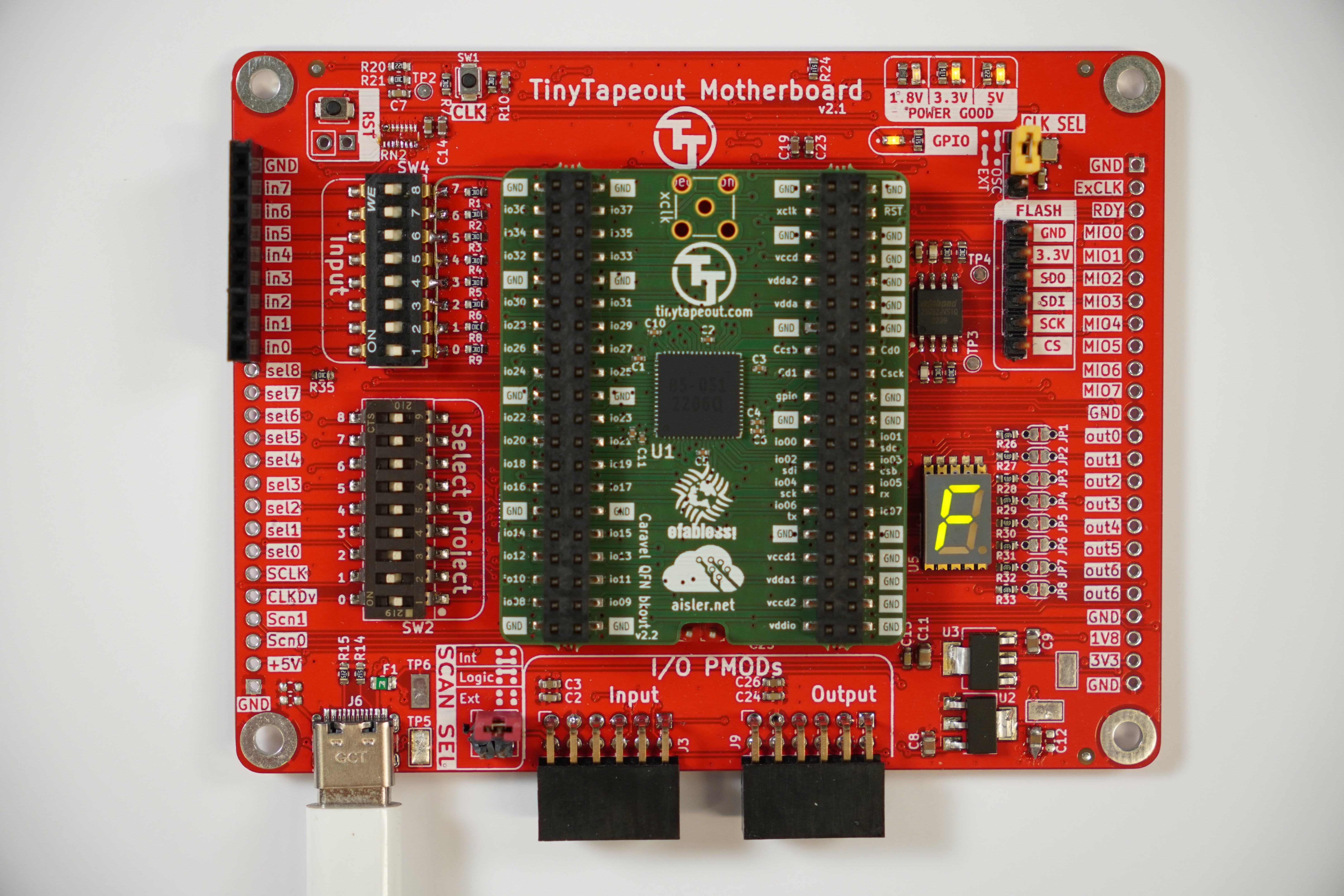
2 layers104.5 × 81 mmMpw mb1, the printed circuit board in 3D

Tiny Tapeout Demo board for TT01, 02 & 03

Size
104.5 × 81 mm
Copper layers
2
Thickness
1.6 mm
Parts
308
Nets
101
Pads
645
Tracks, vias
1,224, 270
Pours
3
Routed
Yes
KiCad
KiCad 7 (file 20221018)
Created
17 Mar 2023
Updated
15 Apr 2024

Overview

Mpw mb1 is an open-source printed circuit board by TinyTapeout, from the TinyTapeout/tt123-demo-pcb repository on GitHub, published under the Apache-2.0 licence. It is a 2-layer board of 104.5 × 81 mm with 308 parts on 101 nets, routed with 1,224 tracks and 270 vias.

It is built around the W25Q32JVSSIQ, TLV1117LV18DCY and TLV1117LV33DCYR, with the WR06X1001FTL, CR0603-FX-5100ELF and WR06X1002FTL among its other parts. Its parts include 34 resistors, 27 capacitors, 14 connectors, 5 ICs and 4 diodes. It belongs with the RP2040 boards of this library.

Main components

12

README

README.md

TinyTapeout Demo Board for chips TT01, TT02 & TT03

Upload to - AISLER

Logo

TinyTapeout is an educational project that makes it easier and cheaper than ever to get your digital designs manufactured on a real chip!

PCB

boards

More photos

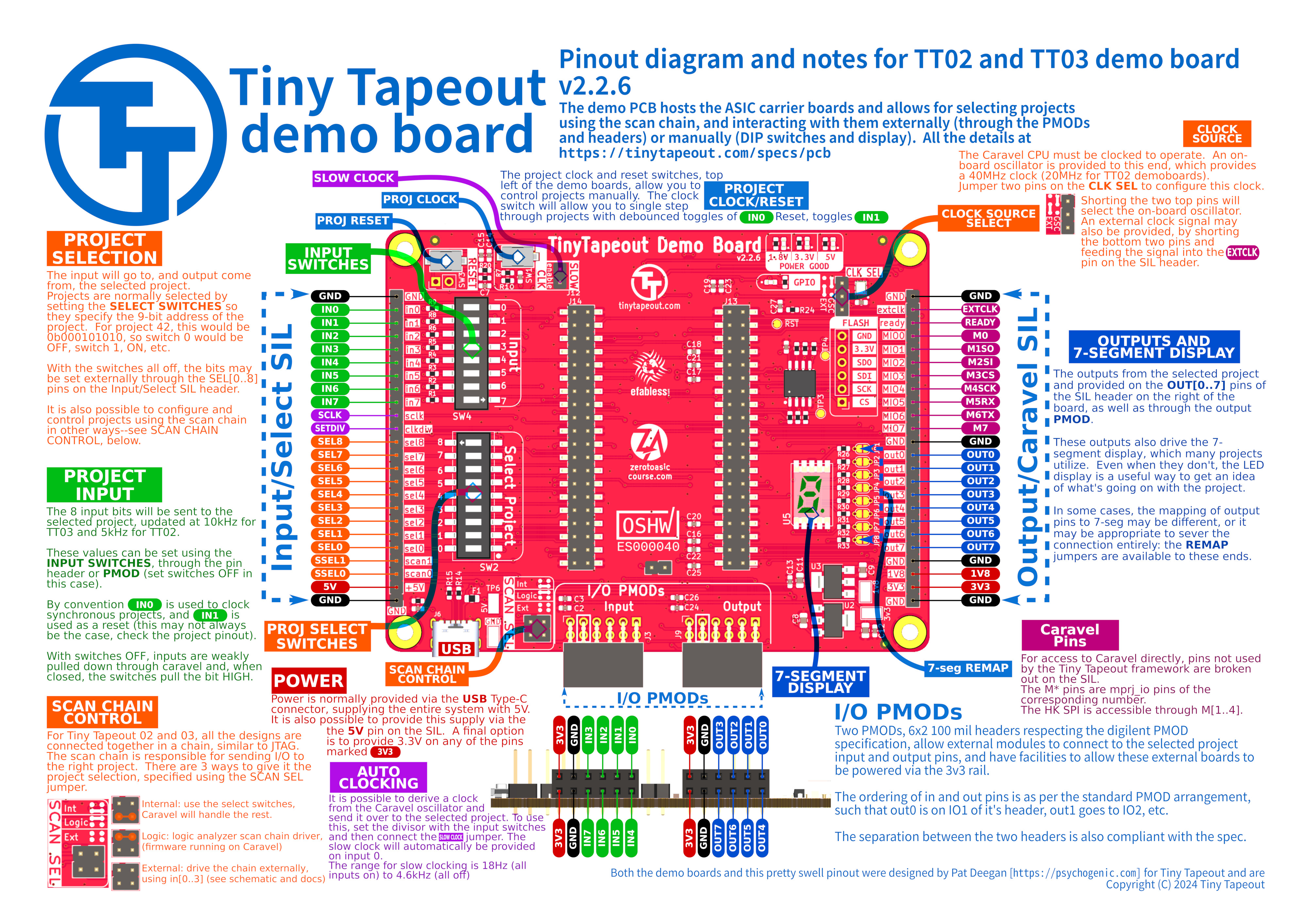
Pinout and Quickstart

pinout

Setup

Select the design you want to load. See here for all the designs:

Plug in the power via USBC and the design should be active. See the documentation for the design for how to test. If there are no docs, open an issue on the design's repo!

Clock divider

To slow down the generated clock:

https://github.com/TinyTapeout/tinytapeout-02/blob/tt02/INFO.md#clock-divider

Firmware

You shouldn't need to update the firmware in most cases.

If you need firmware for external scan controller you can get the firmware from here:

https://github.com/TinyTapeout/tinytapeout-02/tree/tt02/verilog/dv/scan_controller_ext

Compile and flash using the Makefile.

We are very happy to be sponsored by

Features

  • Lots of testpoints, big ground pads
  • Expose useful signals from ASIC:
    • ready - the sync pulse when the chain is updated
    • slow clock
    • the safety scan chain pins (all those starting with ext_scan...)
    • Expose flash programming on a standard cheap footprint for some common USB FTDI programmer
  • Lots of explanatory silkscreen
  • Board version and link to this repo on the silkscreen
  • USB C PSU, 3.3v and 1.8v
  • Adjustable clock / single step
  • 9 DIP switch for design select (or jumpers)
  • 8 DIP switch for inputs - should last for some fiddling but don’t need to be too heavy duty - could be buttons.
  • 8 LEDs for outputs: 7 segment display inc dot
  • Include PMOD headers for IOs
  • Pluggable into breadboard
  • Flash for firmware used to setup GPIO
  • Work for TT01, TT02 & TT03
  • Design for test - single sided probe test points, mounting / alignment holes

Flashing

See the firmware repo here

CHANGELOG

See CHANGELOG.md

Resources

License

Open Source Hardware

ES000040

Parts

308
QtyValueFootprintReferences
170StitchingVia-0.4mmDrillflyingcarsfootprints:StitchingVia-0.4mmDrillSTITCH, STITCH, STITCH, STITCH, STITCH, STITCH, STITCH, STITCH, STITCH, STITCH, STITCH, STITCH, STITCH, STITCH, STITCH, STITCH +154
15100nFCapacitor_SMD:C_0603_1608MetricC1, C2, C5, C6, C7, C12, C13, C16, C17, C18, C20, C21, C22, C24, C25
101kResistor_SMD:R_0603_1608MetricR1, R2, R3, R4, R5, R6, R7, R8, R9, R20
10510Resistor_SMD:R_0603_1608MetricR23, R26, R27, R28, R29, R30, R31, R32, R33, R34
910kResistor_SMD:R_0603_1608MetricR10, R12, R13, R16, R17, R18, R19, R21, R24
8SolderJumper_2_BridgedTinyTapeout:SolderJumper-2_Bridged_Throughole1JP1, JP2, JP3, JP4, JP5, JP6, JP7, JP8
51uFCapacitor_SMD:C_0603_1608MetricC3, C15, C23, C26, C27
410uFCapacitor_SMD:C_0805_2012MetricC8, C9, C10, C11
4Keystone 5019TestPoint:TestPoint_Keystone_5019_MinatureTP5, TP6, TP7, TP8
4MountingHole_PadMountingHole:MountingHole_3.2mm_M3_PadMT1, MT2, MT3, MT4
4YellowLED_SMD:LED_0603_1608MetricD1, D2, D3, D4
3FiducialFiducial:Fiducial_1mm_Mask2mmFID1, FID2, FID3
3StitchingVia-0.3mmflyingcarsfootprints:StitchingVia-0.3mmSTITCHSM1, STITCHSM1, STITCHSM1
3TestPointTestPoint:TestPoint_Pad_D1.5mmTP3, TP4, TP9
210uFCapacitor_SMD:C_0603_1608MetricC14, C19
22x20_P2.54mm_PinheaderTinyTapeout:TT_BREAKOUT_PINHEADER_PLACEHOLDER_WITHPADJ13, J14
2434121025816TinyTapeout:434121025816SW1, SW3
25.1kResistor_SMD:R_0603_1608MetricR14, R15
261300211121Connector_PinHeader_2.54mm:PinHeader_1x02_P2.54mm_VerticalJ8, J12
2613012243121TinyTapeout:PinSocket_2x06_P2.54mm_PMODHost1AJ3, J9
261302411121Connector_PinHeader_2.54mm:PinHeader_1x24_P2.54mm_VerticalJ10, J11
10RResistor_SMD:R_0603_1608MetricR25
11.2KResistor_SMD:R_0603_1608MetricR22
1157112V12700TinyTapeout:WL_S7DS-157112V12700U5
11MResistor_SMD:R_0603_1608MetricR11
120MHzOscillator:Oscillator_SMD_ECS_2520MV-xxx-xx-4Pin_2.5x2.0mmX1
1350mAFuse:Fuse_0805_2012MetricF1
1418121270808TinyTapeout:418121270808SW4
1418121270809TinyTapeout:219-9GULLWINGSW2
16800pFCapacitor_SMD:C_0603_1608MetricC4
1Conn_01x02Connector_PinHeader_2.54mm:PinHeader_1x02_P2.54mm_VerticalJ4
1Conn_01x03Connector_PinHeader_2.54mm:PinHeader_1x03_P2.54mm_VerticalJ5
1Conn_01x06Connector_PinHeader_2.54mm:PinHeader_1x06_P2.54mm_VerticalJ1
1Conn_02x02_Odd_EvenConnector_PinHeader_2.54mm:PinHeader_2x02_P2.54mm_VerticalJ2
1G***kibuzzard-63FCFA48kibuzzard-63FCFA48
1G***kibuzzard-63FCF9FAkibuzzard-63FCF9FA
1G***kibuzzard-63FCF9E0kibuzzard-63FCF9E0
1G***kibuzzard-63FCF9EAkibuzzard-63FCF9EA
1G***kibuzzard-6404270Dkibuzzard-6404270D
1G***kibuzzard-63FCE867kibuzzard-63FCE867
1G***kibuzzard-63FE0D11kibuzzard-63FE0D11
1G***kibuzzard-64031BADkibuzzard-64031BAD
1G***kibuzzard-63FCE860kibuzzard-63FCE860
1G***kibuzzard-63FCFA05kibuzzard-63FCFA05
1G***kibuzzard-63FCE859kibuzzard-63FCE859
1G***kibuzzard-63FCF9CFkibuzzard-63FCF9CF
1LOGOflyingcarsfootprints:PsychoLogoSmallG***
1PicoRPi_Pico:RPi_Pico_SMDU4
1TLV1117LV18Package_TO_SOT_SMD:SOT-223-3_TabPin2U3
1TLV1117LV33Package_TO_SOT_SMD:SOT-223-3_TabPin2U2
1TT03_BREAKOUTTinyTapeout:TT03_BREAKOUT_SMBJ7
1UJC-HP-3-SMT-TRTinyTapeout:CUI_UJC-HP-3-SMT-TRJ6
1W25Q32JVSSPackage_SO:SOIC-8_5.23x5.23mm_P1.27mmU1

The 298 most common of 308 parts.

Similar boards

  • 4 layers104.5 × 81 mmTinytapeout demo, the printed circuit board in 3D

    Tinytapeout demo

    KiCad/kicad-source-mirror

    This is an active mirror of the KiCad development branch, which is hosted at GitLab (updated every time something is pushed). Pull requests on GitHub are not accepted or watched.

    309 parts3.1kGPL-3.0
  • 4 layers85 × 85 mmTinytapeout demo, the printed circuit board in 3D

    Tinytapeout demo

    TinyTapeout/tt-demo-pcb

    Demo board for TT04 and beyond

    330 parts37Apache-2.0
  • 4 layers53.5 × 65.5 mmChipigniteExplain, the printed circuit board in 3D

    ChipigniteExplain

    efabless/chipignite_discover

    This FPGA experimentation and development board was developped for efabless chipignite workshops and labs to serve as an easy to use experimentation board and stepping stone towards ASIC digital design, allowing for…

    251 parts2Apache-2.0
  • 4 layers84 × 78 mmWaferspace main pcb, the printed circuit board in 3D

    Waferspace main pcb

    mole99/waferspace-main-pcb

    Main PCB for wafer.space FABulous FPGA

    276 parts2Apache-2.0
  • 2 layers19 × 19 mmPBSEQ D2, the printed circuit board in 3D

    PBSEQ D2

    CIRCUITSTATE/PBSEQ-D2

    A simple push-button controlled power sequencer circuit demo board.

    22 parts1
  • 2 layers122 × 87 mmOpen PLC Project, the printed circuit board in 3D

    Open PLC Project

    mymy49/Open-PLC-Project

    yss OS를 사용한 오픈 소스/회로 PLC 프로젝트입니다.

    251 partsMIT
  • 2 layers94.9 × 69 mmECU, the printed circuit board in 3D

    ECU

    rivotmotors-rnd/ECU_Firmware_V3

    RIVOT ECU V3.0 Repo containing STM32F446RE firmware and KiCad PCB hardware designs.

    115 parts
  • 4 layers100 × 39.8 mmHPcontroller, the printed circuit board in 3D

    HPcontroller

    Aylo6061/PCBHotplate

    A USB C powered PCB-based hotplate

    72 parts6

Questions

How big is the Mpw mb1 PCB?

It measures 104.5 × 81 mm and has 2 copper layers, 1.6 mm thick.

What parts does the Mpw mb1 use?

308 parts, built around the W25Q32JVSSIQ, TLV1117LV18DCY, TLV1117LV33DCYR and WR06X1001FTL. The full list of its parts is on this page, with links to each part's symbol and footprint where PCBKit's library has them.

Where can I download the Mpw mb1 KiCad files?

From the TinyTapeout/tt123-demo-pcb repository on GitHub, at the commit this page was made from: the board is mpw-mb1.kicad_pcb and its schematic mpw-mb1.kicad_sch. PCBKit opens the board in the browser, with nothing to install.

Can I use the Mpw mb1 design in my own project?

Its repository publishes it under the Apache-2.0 licence: you may reuse it on that licence's terms (keep the author's notice, and for a copyleft licence share your changes alike).