
2 layers99.9 × 99.9 mm

 tinkermax/split-flap13
DIY mechanical spli-flap display
Split flap units is an open-source printed circuit board by tinkermax, from the tinkermax/split-flap repository on GitHub, published under the CC-BY-4.0 licence. It is a 2-layer board of 99.8 × 50.1 mm with 27 parts on 47 nets, routed with 266 tracks and 2 vias.
It is built around the A4988 and B5B-XH-A(LF)(SN). Its parts include 10 connectors and 9 capacitors. It belongs with the lEDs and displays boards of this library.
You can find full details and discussion on my blog.
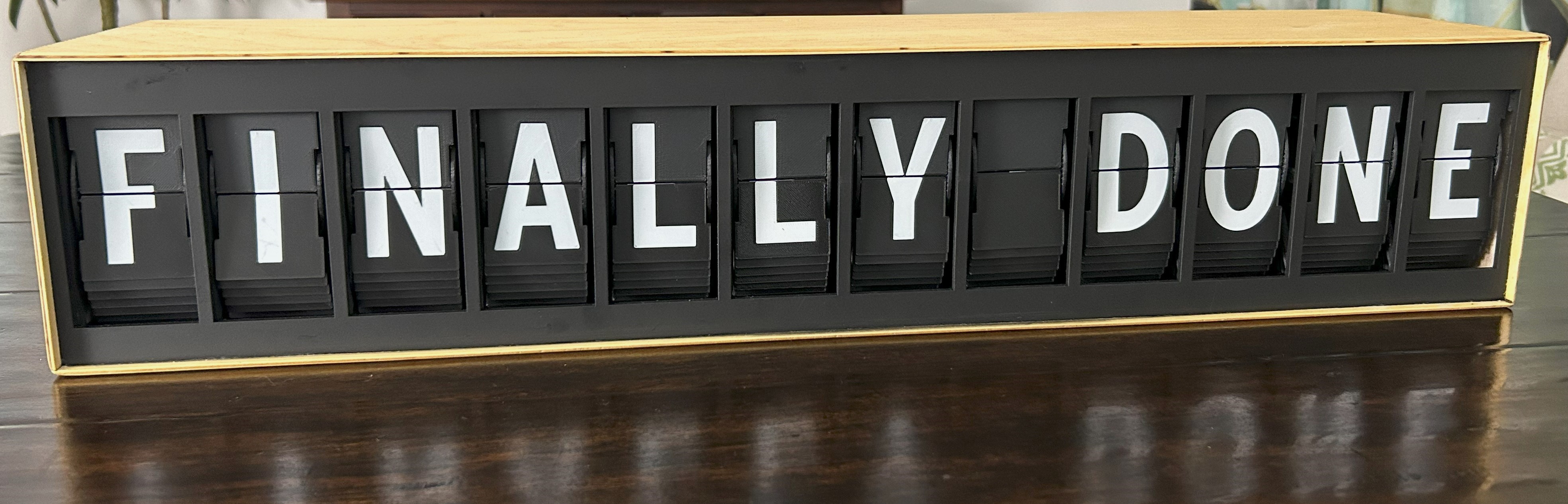
This is an alternate electronics and firmware for David Kingsman's Split-Flap Display.
DEBUG 1
unitCount 12
NETWORKNAME "splitflap"
calOffsetUnit : an array of the offsets to move from hall sensor trigger to blank flap
FlapStep : an array containing the number of steps per stepper revolution (then divided by 45 flaps)
WIFI_SSID "mySSID"
WIFI_PWD "myPassword"
MY_NTP_SERVER "au.pool.ntp.org" // Set the best fitting NTP server (pool) for your location
MY_TZ "AEST-10AEDT,M10.1.0,M4.1.0/3" // Set your time zone from https://github.com/nayarsystems/posix_tz_db/blob/master/zones.csv
WORDNIKAPIKEY "" // Get your private key from https://developer.wordnik.com/
MINWORDLEN 9 // Specify minimum word length to fetch from Wordnik
WORDUPDATESPERHOUR 1 // Set number of word updates from https://wordnik.com per hour. 0 will disable, else use an integer that results in an exact number of minutes btw updates i.e. 1,2,3,4,5,6,10,12,15,20,30 or 60
This project makes extensive use of two libraries:
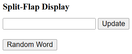
{
    displaytext: "Display Text"
}
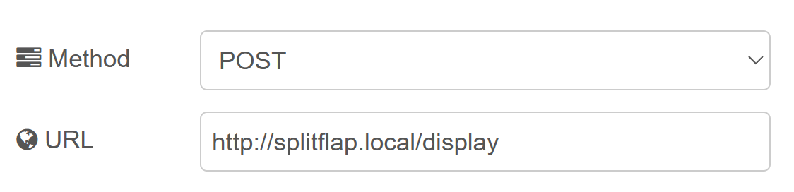
For example, you could use the request node within node-red:
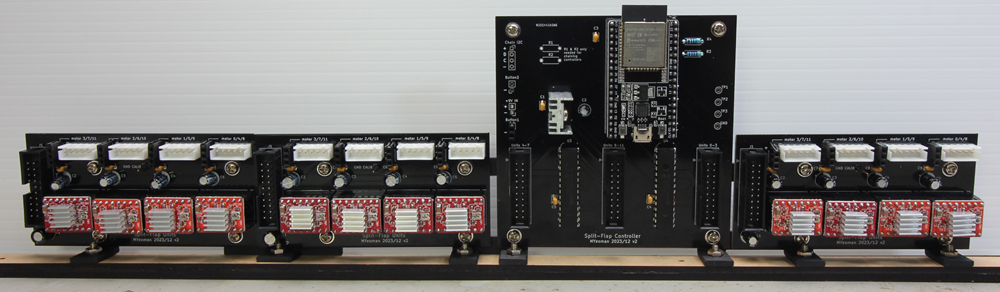
Schematics for the Controller and Unit PCBs can be found under schematics.
Gerbers, Bill of materials and Kicad source files can be found under PCBs.
PCB mounting brackets can be found on Printables.
Also found there is my remixed unit frame. This is optional, as you could still use the original frames with the new electronics.
My unit frame requires an additional two M3*L3*D4 heat inserts for connecting to the adjacent unit.
front
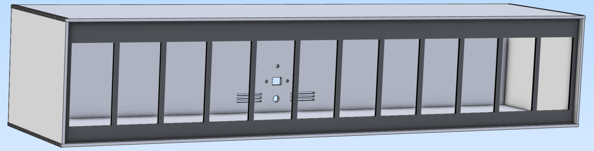
rear
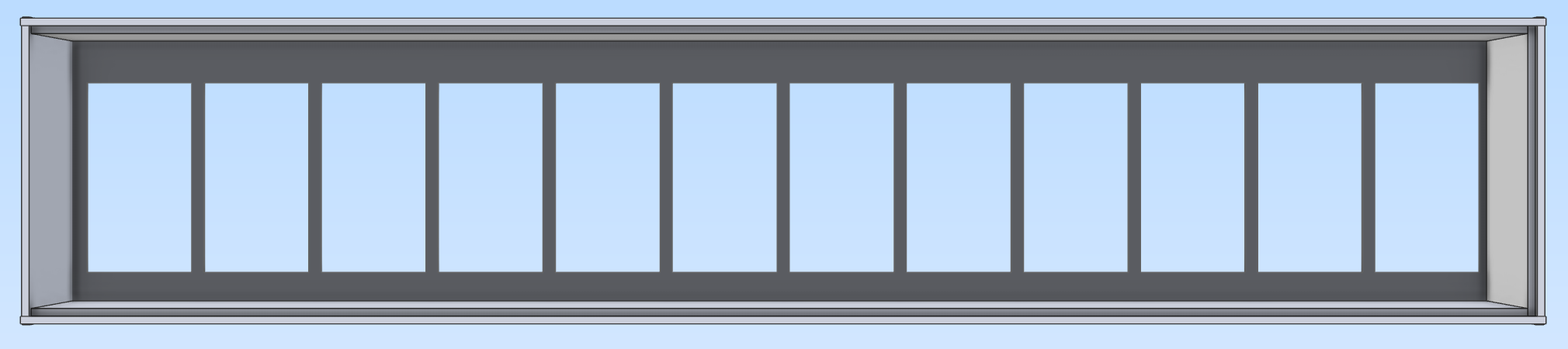
Plywood (3mm) files for laser cutting are in enclosure
Copyright (c) 2024 Malcolm Yeoman.
Electronics is released under CERN-OHL-P (Permissive) V2.
Firmware is released under the MIT License.
Documentation is licensed under a Creative Commons Attribution 4.0 International License.
| Qty | Value | Footprint | References |
|---|---|---|---|
| 5 | 100uF | Capacitor_THT:CP_Radial_D6.3mm_P2.50mm | C1, C2, C3, C4, C5 |
| 4 | 100nF | Capacitor_THT:C_Disc_D3.4mm_W2.1mm_P2.50mm | C6, C7, C8, C9 |
| 4 | A4988 | User:A4988_Stepper_Module | A1, A2, A3, A4 |
| 4 | MountingHole_3.2mm_M3_Pad | MountingHole:MountingHole_3.2mm_M3_Pad | REF1, REF2, REF3, REF4 |
| 1 | GND CALIB | Connector_PinHeader_2.54mm:PinHeader_1x01_P2.54mm_Vertical | J2 |
| 1 | Units 0-3 | Connector_IDC:IDC-Header_2x10_P2.54mm_Vertical | J1 |
| 1 | motor 0/4/8 | Connector_JST:JST_XH_B5B-XH-A_1x05_P2.50mm_Vertical | J10 |
| 1 | motor 1/5/9 | Connector_JST:JST_XH_B5B-XH-A_1x05_P2.50mm_Vertical | J8 |
| 1 | motor 2/6/10 | Connector_JST:JST_XH_B5B-XH-A_1x05_P2.50mm_Vertical | J6 |
| 1 | motor 3/7/11 | Connector_JST:JST_XH_B5B-XH-A_1x05_P2.50mm_Vertical | J4 |
| 1 | sens0 | Connector_PinSocket_2.54mm:PinSocket_1x03_P2.54mm_Vertical | J9 |
| 1 | sens1 | Connector_PinSocket_2.54mm:PinSocket_1x03_P2.54mm_Vertical | J7 |
| 1 | sens2 | Connector_PinSocket_2.54mm:PinSocket_1x03_P2.54mm_Vertical | J5 |
| 1 | sens3 | Connector_PinSocket_2.54mm:PinSocket_1x03_P2.54mm_Vertical | J3 |

rimuadmin/TeensyMaestro-Hardware
Hardware for the TeensyMaestro


kaihchang/Kai_Simple_split_keyboard
Kai Simple is a cradio (or some call it Sweep) variation that fits author's hands best. Author's first KB design: https://github.com/kaihchang/Ascendsplaysplitkeyboard


AndreyPodlesni/stm32wl-lora-rf-pcb
4-layer RF PCB design of a low-power LoRa sensor node based on STM32WLE5CCU6, featuring 50Ω controlled impedance RF routing, SMA antenna interface, and HDC2022 temperature & humidity sensor. Designed in KiCad.

doug7410/nowplaying-appliance
Build guide, BOM and hardware for the Now-Playing desk appliance: HUB75 spectrum + touch now-playing display driven by room-mic song recognition


Emwm/BikeLightIoT7
An ESP32-based smart tracking and monitoring system for bicycles, combining GNSS (GPS) tracking, motion detection, power management, battery monitoring, and LoRa communication to create an intelligent, low-power system…
It measures 99.8 × 50.1 mm and has 2 copper layers, 1.6 mm thick.
27 parts, built around the A4988 and B5B-XH-A(LF)(SN). The full list of its parts is on this page, with links to each part's symbol and footprint where PCBKit's library has them.
From the tinkermax/split-flap repository on GitHub, at the commit this page was made from: the board is PCBs/Kicad/Units/split-flap-units.kicad_pcb and its schematic PCBs/Kicad/Controller/split-flap.kicad_sch. PCBKit opens the board in the browser, with nothing to install.
Its repository publishes it under the CC-BY-4.0 licence: you may reuse it on that licence's terms (keep the author's notice, and for a copyleft licence share your changes alike).