

4 layers160 × 170 mm
Analog matrix lc1
tim4431/analog_programmable_matrix
DC-coupled 4x4 programmable analog matrix: signed gains, 1 MHz target, BNC I/O, Pico control, KiCad PCB and enclosure CAD.
393 parts
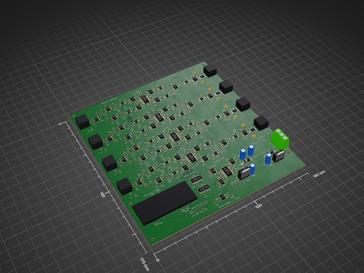
 tim4431/analog_programmable_matrix
DC-coupled 4x4 programmable analog matrix: signed gains, 1 MHz target, BNC I/O, Pico control, KiCad PCB and enclosure CAD.
Analog matrix 4x4 3d is an open-source printed circuit board by tim4431, from the tim4431/analog_programmable_matrix repository on GitHub. It is a 4-layer board of 160 × 170 mm with 434 parts on 296 nets, routed with 7,959 tracks and 998 vias.
It is built around the OPA197ID, ADA4899-1YRDZ and OPA810ID, with the AD5544BRSZ, THS3091DDAR and TMUX6219DGKR among its other parts. Its parts include 200 capacitors, 146 resistors, 71 ICs, 9 connectors and 2 diodes. It belongs with the lEDs and displays boards and the RP2040 boards of this library.


A four-input, four-output, DC-coupled analog matrix for programmable addition, subtraction, and signal mixing. A Raspberry Pi Pico sets sixteen static signed coefficients over USB; the signals remain in the analog domain.
$$b_i = \sum_{j=0}^{3} M_{ij}a_j, \qquad -1 \leq M_{ij} \leq 1$$
This first public version contains PCB D and enclosure M3, without the added power-indicator LED. It is an unbuilt prototype: the 1 MHz bandwidth and approximately 1% gain accuracy are design targets supported by circuit simulations, not measured hardware specifications.
A separate LC1 lower-cost 12-bit design is also included. It preserves the original design and enclosure interface, reduces the listed component count from 428 to 387, and replaces the expensive multiplying DACs. LC1 has its own schematic, PCB, firmware, sourcing notes and simulation evidence. The renders below show the original Revision D.
These are renders generated from the CAD, not photographs of manufactured hardware.
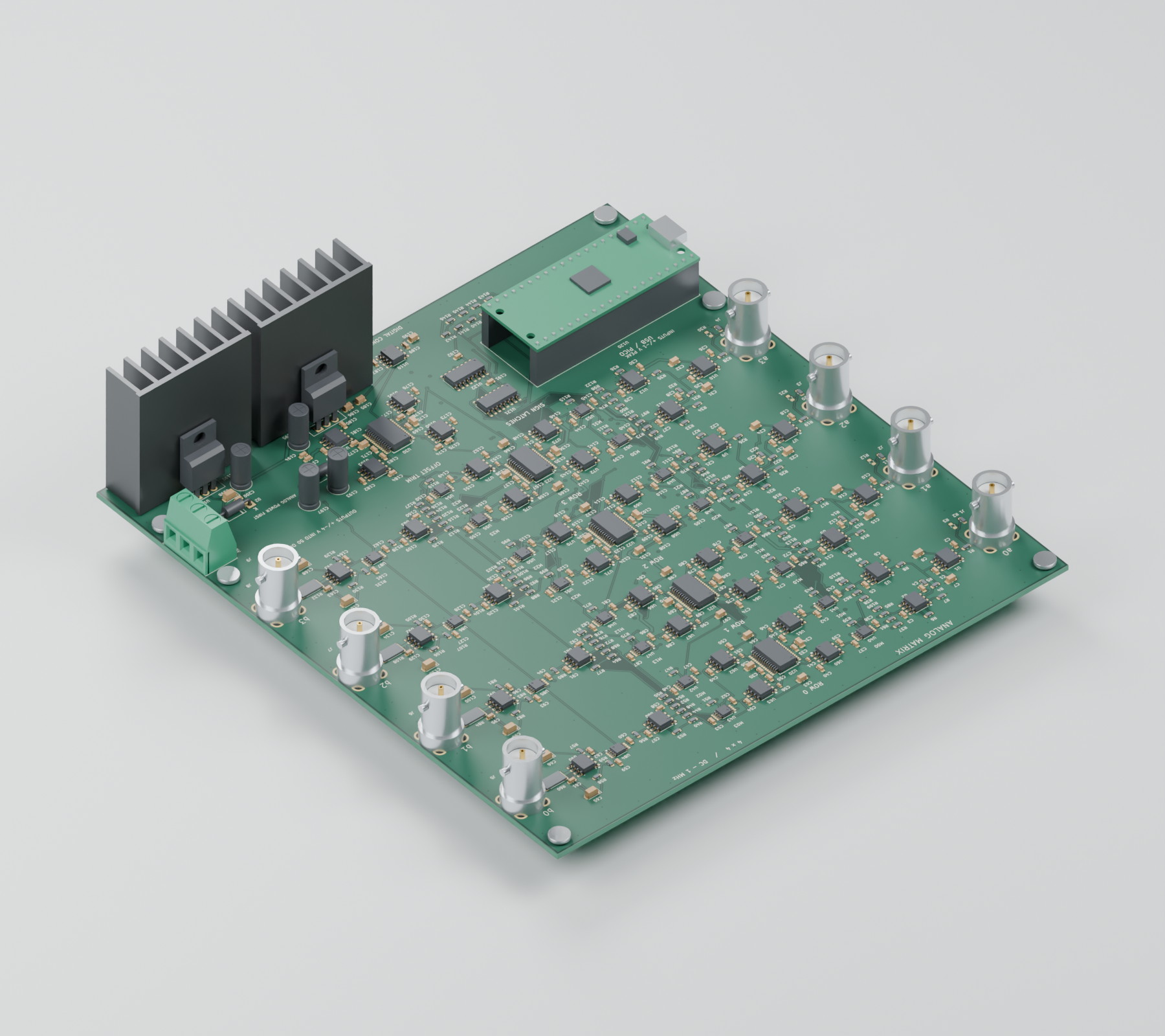
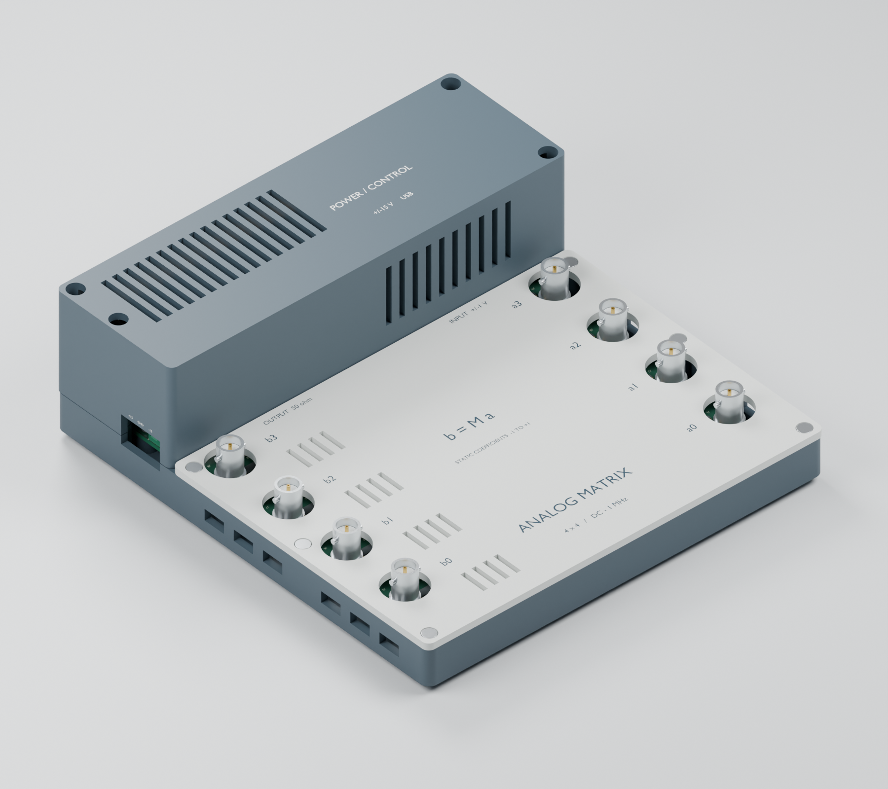
Exploded enclosure render · Dimensioned drawing
| Item | Design |
|---|---|
| Matrix | 4 × 4, independently programmable signed coefficients |
| Signal range | DC through 1 MHz target; ±1 V peak per input |
| Inputs | Four vertical BNCs; high impedance by default |
| Outputs | Four vertical BNCs; up to ±4 V peak into an external 50 Ω load |
| Output termination | 49.9 Ω series source resistor; a high-impedance receiver sees approximately twice the loaded voltage |
| Coefficient control | 16-bit multiplying DACs and analog polarity switches |
| Controller | Original Raspberry Pi Pico, MicroPython, USB serial JSON commands |
| Supply | External regulated ±15 V plus USB for the Pico; onboard ±5 V analog regulators |
| PCB | 160 × 170 mm, four copper layers, nominal 1.6 mm FR-4 |
| Enclosure | 180 × 192 × 60 mm; 62.5 mm including feet |
| Cooling | Two 38.1 mm heatsink envelopes; passive ventilation |
The input amplifiers generate buffered positive and negative versions of each input. Each matrix cell selects a polarity with a TMUX6219 and sets its magnitude with an AD5544 multiplying DAC and ADA4899-1 transimpedance stage. A summing amplifier combines the four contributions for each output, followed by a THS3091 driver and a 49.9 Ω source resistor. A fifth AD5544 supplies four offset-trim controls.
The Pico changes DAC codes and switch states; it does not digitize or synthesize the waveform. Firmware starts with the outputs muted and temporarily mutes them during coefficient changes. Coefficient and offset calibration are performed through USB commands.
The Releases page contains ZIP downloads, including the complete populated-board and enclosure STEP assemblies. The two large assembly STEP exports are distributed there rather than duplicated in Git.
Install the supplied firmware/main.py on the original Pico running MicroPython. Apply the analog supplies before USB power, then send newline-terminated JSON commands over the Pico's USB serial console:
{"cmd":"set","matrix":[[1,0,0,0],[0,1,0,0],[0,0,1,0],[0,0,0,1]]}
{"cmd":"arm"}
Rows select outputs and columns select inputs. For example, [0.5,-0.5,0,0] makes that output half the difference between the first two inputs. Use {"cmd":"mute"} to mute the outputs and {"cmd":"status"} to read the current state.
The initial gain scale is an estimate. Follow the calibration procedure to measure both coefficient signs and each row's offset with the intended 50 Ω loads.
The supplied checks report zero KiCad schematic errors, PCB design-rule violations, unrouted connections, or schematic/PCB mismatches. Nominal enclosure collision checks pass, and all three printable parts are watertight, single-shell meshes. The BNC access review checks all eight straight-plug positions; the two beside the raised hood need a side grip.
Circuit-level SPICE results show about 0.758% gain reduction at 1 MHz after DC normalization and approximately 119 ns settling to 1% in the nominal row model. Read MODEL_SCOPE.txt: the multiplying-DAC model is approximate, parts of the full-row test are idealized, and the 1 nF load transient remains unresolved. These results do not establish 1% relative accuracy at small coefficients or validate PCB parasitics.
Thermal testing is still required. The analog circuit dissipates roughly 10 W at idle; each ±5 V regulator loses roughly 3 W. The modeled heatsinks are clearance envelopes, not qualified purchased parts. Follow the thermal calculation and first-article acceptance procedure before sustained operation.
The assembly export contains 406 fitted SMT components, 18 separate through-hole/module items, and four intentionally unpopulated input-termination resistors. Upload these files to JLCPCB:
Supplier matching is incomplete. Do not treat the six existing LCSC identifiers as reserved assembly inventory. Check every selected part's package and pin-1 orientation, and obtain CAM acceptance for epoxy-filled/copper-capped via-in-pad fabrication, including the 0.20 mm thermal holes. The handoff notes describe the exact stack, drill and placement conventions.
The requested initial build is two assembled boards. No order has been submitted or paid.
Run python tools/verify_release.py to verify the stored design hash, check reports, BOM/CPL references, and simulation netlist evidence. It checks the delivered files; it does not rerun SPICE or physical tests.
For fresh electrical checks, use KiCad's kicad-cli sch erc and kicad-cli pcb drc --schematic-parity on the project. The scripts in the project's tools/ directory compare symbol pins, footprints, and the exported netlist.
Mechanical sources are mechanical/analog_matrix_package_m3/build_package.py (CadQuery 2.8) and render_package.py (Blender 4.3). The included geometry, models, and PCB texture allow the current assembly and renders to be regenerated. The auxiliary export scripts use KiCad's Python environment and Windows installation paths, which may need adjustment on another system.
Final simulation benches and their recorded results are retained under spice/. Manufacturer macromodel downloads are excluded from Git; use python spice/fetch_models.py with TI's model downloads and a local LTspice installation, then python spice/replay.py --bench a2_row_sine_rc.cir. See simulation setup.
KiCad footprint/model licensing and attribution are included beside the libraries. TI and Analog Devices simulation models retain their manufacturers' terms and are not covered by any implied project-wide license. See third-party notices. A project-wide license for the original design has not yet been selected.
| Qty | Value | Footprint | References |
|---|---|---|---|
| 136 | 100n | AnalogMatrix:C_0603_1608Metric | C1, C10, C11, C101, C103, C105, C106, C107, C108, C110, C111, C112, C113, C115, C116, C117 +120 |
| 32 | 1.00 k | AnalogMatrix:R_0603_1608Metric | R15, R16, R17, R18, R24, R25, R26, R27, R33, R34, R35, R100, R112, R116, R120, R124 +16 |
| 32 | 150R 0.1% | AnalogMatrix:R_0603_1608Metric | R37, R38, R41, R42, R45, R46, R49, R50, R109, R110, R113, R114, R117, R118, R121, R122 +16 |
| 20 | 100 k | AnalogMatrix:R_0603_1608Metric | R39, R43, R47, R51, R57, R63, R67, R71, R75, R81, R105, R111, R115, R119, R123, R129 +4 |
| 20 | TMUX6219DGKR | AnalogMatrix:VSSOP-8_3x3mm_P0.65mm | U40, U41, U42, U43, U44, U45, U46, U47, U48, U49, U50, U51, U52, U53, U54, U55 +4 |
| 18 | 10u | AnalogMatrix:C_0805_2012Metric | C7, C8, C15, C16, C23, C24, C31, C32, C63, C64, C131, C132, C165, C166, C185, C186 +2 |
| 16 | 2.2p | AnalogMatrix:C_0402_1005Metric | C41, C46, C51, C56, C75, C80, C85, C90, C109, C114, C119, C124, C143, C148, C153, C158 |
| 16 | ADA4899-1YRDZ | AnalogMatrix:ADA4899_RD8_EP2.29x2.29 | U60, U61, U62, U63, U64, U65, U66, U67, U68, U69, U70, U71, U72, U73, U74, U75 |
| 16 | OPA810ID | AnalogMatrix:SOIC-8_3.9x4.9mm_P1.27mm | U1, U2, U3, U4, U5, U6, U7, U8, U9, U10, U11, U12, U80, U81, U82, U83 |
| 12 | 1u | AnalogMatrix:C_0805_2012Metric | C34, C36, C68, C70, C102, C104, C136, C138, C170, C172, C188, C190 |
| 9 | 10 k | AnalogMatrix:R_0603_1608Metric | R138, R139, R140, R141, R142, R143, R144, R145, R146 |
| 9 | 33R | AnalogMatrix:R_0603_1608Metric | R1, R10, R19, R28, R133, R134, R135, R136, R137 |
| 8 | 49.9R | AnalogMatrix:R_0603_1608Metric | R3, R12, R21, R30, R56, R80, R104, R128 |
| 8 | 499R | AnalogMatrix:R_0603_1608Metric | R4, R5, R13, R14, R22, R23, R31, R32 |
| 8 | 6.8u | AnalogMatrix:CP_EIA-3216-18_Kemet-A | C65, C66, C99, C100, C133, C134, C167, C168 |
| 8 | BNC 031-5329-52RFX | AnalogMatrix:BNC_Amphenol_031-5329-52RFX_Vertical | J1, J2, J3, J4, J5, J6, J7, J8 |
| 6 | MountingHole_3.2mm_M3 | MountingHole_3.2mm_M3 | H1, H2, H3, H4, H5, H6 |
| 5 | AD5544BRSZ | AnalogMatrix:SSOP-28_5.3x10.2mm_P0.65mm | U20, U21, U22, U23, U30 |
| 4 | 1 M | AnalogMatrix:R_0603_1608Metric | R2, R11, R20, R29 |
| 4 | 1.21 k | AnalogMatrix:R_0603_1608Metric | R58, R82, R106, R130 |
| 4 | 10.0 k | AnalogMatrix:R_0603_1608Metric | R54, R78, R102, R126 |
| 4 | 100p C0G | AnalogMatrix:C_0603_1608Metric | C175, C178, C181, C184 |
| 4 | 20.0 k | AnalogMatrix:R_0603_1608Metric | R55, R79, R103, R127 |
| 4 | 402R | AnalogMatrix:R_0603_1608Metric | R59, R83, R107, R131 |
| 4 | 49.9R | AnalogMatrix:R_2512_6332Metric | R60, R84, R108, R132 |
| 4 | 523R | AnalogMatrix:R_0603_1608Metric | R53, R77, R101, R125 |
| 4 | OPA197ID | AnalogMatrix:SOIC-8_3.9x4.9mm_P1.27mm | U100, U101, U102, U103 |
| 4 | THS3091DDAR | AnalogMatrix:SOIC-8-1EP_3.9x4.9mm_P1.27mm_EP2.95x4.9mm_Mask2.71x3.4mm_ThermalVias | U90, U91, U92, U93 |
| 2 | 10u | AnalogMatrix:C_Radial_D5.0mm_H11.0mm_P2.00mm | C195, C199 |
| 2 | 1N4002 | AnalogMatrix:D_DO-41_SOD81_P10.16mm_Horizontal | D1, D2 |
| 2 | 47u | AnalogMatrix:C_Radial_D5.0mm_H11.0mm_P2.00mm | C193, C197 |
| 2 | SN74HC595D | AnalogMatrix:SOIC-16_3.9x9.9mm_P1.27mm | U121, U122 |
| 1 | 2.2u | AnalogMatrix:CP_EIA-3216-18_Kemet-A | C198 |
| 1 | 3-pin terminal | AnalogMatrix:TerminalBlock_Phoenix_MKDS-1,5-3-5.08_1x03_P5.08mm_Horizontal | J9 |
| 1 | 330n | AnalogMatrix:C_0603_1608Metric | C194 |
| 1 | ADR4525BRZ | AnalogMatrix:SOIC-8_3.9x4.9mm_P1.27mm | U110 |
| 1 | L7805CV | AnalogMatrix:TO-220-3_Vertical | U130 |
| 1 | L7905CV | AnalogMatrix:TO-220-3_Vertical | U131 |
| 1 | Pico | AnalogMatrix:Pico_2x20_Socket_17.78mm | U120 |
tim4431/analog_programmable_matrix
DC-coupled 4x4 programmable analog matrix: signed gains, 1 MHz target, BNC I/O, Pico control, KiCad PCB and enclosure CAD.

YiyoChimal/NASA_Space_Apps_2024_Mecha_Cintli
Leveraging Earth Observation Data for Informed Agricultural Decision-Making


pratham-cloud-ctrl/Project-SCCI-RH
A digital spinal cord-computer interface concept: research, eight KiCad boards, nRF5340 firmware and FreeCAD assemblies.

gallicchio/AMOD-and-RFMOD
The tutorial's 2x12 adapter (/mudd/133electronics/icepi-zero-dac-adc/adapterboard/) with a 2 x 6 right-angle Pmod socket on a 15 mm extension of its right-hand end, so an Icepi Zero can drive AMOD-A's and RF-MOD's Pmod…


MKesenheimer/fault-injection-library
Python library to perform fault-injection attacks on microcontrollers

It measures 160 × 170 mm and has 4 copper layers, 1.6 mm thick.
434 parts, built around the OPA197ID, ADA4899-1YRDZ, OPA810ID and AD5544BRSZ. The full list of its parts is on this page, with links to each part's symbol and footprint where PCBKit's library has them.
From the tim4431/analog_programmable_matrix repository on GitHub, at the commit this page was made from: the board is mechanical/analog_matrix_package_m3/analog_matrix_4x4_3d.kicad_pcb and its schematic pcb/analog_matrix_4x4_rev_d/analog_matrix_4x4.kicad_sch. PCBKit opens the board in the browser, with nothing to install.
Its repository states no licence, so its author keeps all rights: ask tim4431 before reusing the design.