
4 layers91.4 × 40.6 mm
Mta1 usb dev
tillitis/tk1-pcba
PCB files for the open and flexible security key - TKey
92 parts4CERN-OHL-S-2.0

PCB files for the open and flexible security key - TKey
Tk1 is an open-source printed circuit board by tillitis, from the tillitis/tk1-pcba repository on GitHub, published under the CERN-OHL-S-2.0 licence. It is a 4-layer board of 28.6 × 13.9 mm with 70 parts on 77 nets, routed with 507 tracks and 90 vias.
It is built around the CH552E, ICE40UP5K-SG48ITR50 and PT2043AT6, with the W25Q80DVUXIE, MIC5258-1.2YM5 and USBLC6-2SC6 among its other parts. Its parts include 20 capacitors, 15 resistors, 8 ICs, 2 diodes and 1 connector. It belongs with the FPGA and CPLD and 8051 (CH55x, STC, AT89) boards of this library.


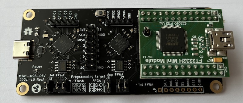
This is the original TKey design, intended as a development platform. It is a larger PCB, that connects to a PC via a USB C cable.
Main features:
2 ICE40 FPGAs.
The first ICE40 (Interface FPGA) is connected to a USB C plug, and is loaded with a gateware that contains a soft USB device. This gateware acts as an USB-to-GPIO interface to the second ICE40.
The second ICE40 (application FPGA) is loaded with a RISC-V soft core containing the security firmware. User applications are run on this gateware.
The second ICE40 also has an input button for user presenence detection.
An FTDI module is included for programming both the Application and Interface FPGAs.
Both ICE40s can be configured to boot from included SPI flash memories, NVCM, or be live programmed from the FTDI module.
All GPIO lines between the two FPGAs, as well as all programming signals, are exposed on 0.1" headers for probing.
| Qty | Value | Footprint | References |
|---|---|---|---|
| 11 | 0.10uF | mta1:CAPC1005X06L | C7, C13, C16, C17, C18, C19, C20, C21, C22, C23, C26 |
| 9 | 10k | mta1:ERJ2G(0402)_L | R1, R2, R19, R20, R22, R23, R24, R25, R26 |
| 7 | 10uF | mta1:CAPC1608X09L | C1, C2, C3, C4, C5, C6, C25 |
| 4 | 1k | mta1:ERJ2G(0402)_L | R3, R16, R17, R18 |
| 2 | Fiducial | Fiducial:Fiducial_0.75mm_Mask1.5mm | FID1, FID2 |
| 1 | 0402 indicator LED, blue | LED_SMD:LED_0402_1005Metric | D1 |
| 1 | 1V2 | mta1:TestPoint_Pad_D1.0mm | TP4 |
| 1 | 1pF | mta1:CAPC1005X06L | C27 |
| 1 | 1uF | Capacitor_SMD:C_1206_3216Metric | C8 |
| 1 | 2V5 | mta1:TestPoint_Pad_D1.0mm | TP3 |
| 1 | 2k | mta1:ERJ2G(0402)_L | R30 |
| 1 | 3V3 | mta1:TestPoint_Pad_D1.0mm | TP2 |
| 1 | 5.1k | mta1:ERJ2G(0402)_L | R29 |
| 1 | 5V | mta1:TestPoint_Pad_D1.0mm | TP1 |
| 1 | APP_CDONE | mta1:TestPoint_Pad_D1.0mm | TP17 |
| 1 | APP_CRESET | mta1:TestPoint_Pad_D1.0mm | TP16 |
| 1 | APP_GND | mta1:TestPoint_Pad_D1.0mm | TP5 |
| 1 | APP_GPIO1 | mta1:TestPoint_Pad_D1.0mm | TP18 |
| 1 | APP_GPIO2 | mta1:TestPoint_Pad_D1.0mm | TP19 |
| 1 | APP_GPIO3 | mta1:TestPoint_Pad_D1.0mm | TP20 |
| 1 | APP_GPIO4 | mta1:TestPoint_Pad_D1.0mm | TP21 |
| 1 | APP_ICE_MISO | mta1:TestPoint_Pad_D1.0mm | TP15 |
| 1 | APP_ICE_MOSI | mta1:TestPoint_Pad_D1.0mm | TP14 |
| 1 | APP_ICE_SCK | mta1:TestPoint_Pad_D1.0mm | TP12 |
| 1 | APP_ICE_SS | mta1:TestPoint_Pad_D1.0mm | TP13 |
| 1 | BLM18KG300TN1D | mta1:Ferritbead_0603_1608Metric | FB3 |
| 1 | CH552E | Package_SO:MSOP-10_3x3mm_P0.5mm | U3 |
| 1 | GND | mta1:TestPoint_Pad_D1.0mm | TP28 |
| 1 | ICE40UP5K-SG48ITR | Package_DFN_QFN:QFN-48-1EP_7x7mm_P0.5mm_EP5.6x5.6mm | U6 |
| 1 | INT_CTS | mta1:TestPoint_Pad_D1.0mm | TP9 |
| 1 | INT_RTS | mta1:TestPoint_Pad_D1.0mm | TP8 |
| 1 | INT_RX | mta1:TestPoint_Pad_D1.0mm | TP7 |
| 1 | INT_TX | mta1:TestPoint_Pad_D1.0mm | TP6 |
| 1 | LED_ARGB | mta1:0402rgb-1010 | D3 |
| 1 | MCP1824T-2502EOT | Package_TO_SOT_SMD:SOT-23-5 | U1 |
| 1 | MIC5258-1.2YM5 | Package_TO_SOT_SMD:SOT-23-5 | U2 |
| 1 | NCP752BSN33T1G | mta1:NCP752BSN33T1G | U9 |
| 1 | PT2043AT6 | Package_TO_SOT_SMD:SOT-23-6 | U10 |
| 1 | USBLC6-2SC6 | Package_TO_SOT_SMD:SOT-23-6 | U5 |
| 1 | USB_C_Plug | mta1:U261-241N-4BS60 | P1 |
| 1 | W25Q80DVUXIE | mta1:W25Q80DVUXIE | U8 |
The 69 most common of 70 parts.
It measures 28.6 × 13.9 mm and has 4 copper layers, 0.8 mm thick.
70 parts, built around the CH552E, ICE40UP5K-SG48ITR50, PT2043AT6 and W25Q80DVUXIE. The full list of its parts is on this page, with links to each part's symbol and footprint where PCBKit's library has them.
From the tillitis/tk1-pcba repository on GitHub, at the commit this page was made from: the board is hw/tk1.kicad_pcb and its schematic hw/application_fpga.kicad_sch. PCBKit opens the board in the browser, with nothing to install.
Its repository publishes it under the CERN-OHL-S-2.0 licence: you may reuse it on that licence's terms (keep the author's notice, and for a copyleft licence share your changes alike).
tillitis/tk1-pcba
PCB files for the open and flexible security key - TKey

kr-Eliza/tkey-open-hardware-reproduction
Reproducing the Tillitis TKey open hardware security key: 2-layer hand-solderable PCB, lab assembly and bring-up, Voltera prototype, SBOM


alex-chuf/PCBs-for-Project-North-Star-Next
This USB3 Hub board is specially used on some AR/VR DIY project, that requires:


Anish-Agarwall/Polaris-Flight-Computer
A flight computer designed during my freshman year in university for my Rocketry Organization