2 layers94.1 × 63.5 mm
GarageOpener
AshiqAshref/Garage-Door-Opener
Universal Garage Door using BLE (Bluetooth Low Power) running on ESP32 with highest security possible.
42 partsMIT
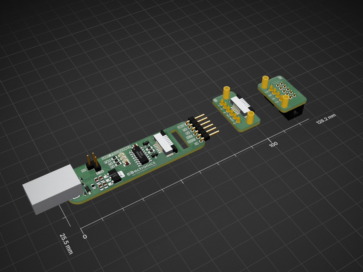
 TiebeDeclercq/Uart-programmer
A versatile UART programming board designed for microcontroller development with flexible voltage selection and multiple connection options. Features built-in status LEDs, CH340C USB-to-serial conversion, and support for external programming fixtures.
Universal Programmer is an open-source printed circuit board by TiebeDeclercq, from the TiebeDeclercq/Uart-programmer repository on GitHub, published under the MIT licence. It is a 2-layer board of 126.2 × 25.5 mm with 46 parts on 26 nets, routed with 259 tracks and 36 vias.
It is built around the CH340C, AMS1117-3.3 and LESD5D5.0CT1G, with the MMBT3904 and 1N5819HW-7-F-01 among its other parts. Its parts include 15 connectors, 7 diodes, 6 capacitors, 5 resistors and 2 ICs. It belongs with the interfaces and adapters boards of this library.


A versatile UART programming board designed for microcontroller development with flexible voltage selection and multiple connection options. Features built-in status LEDs, CH340C USB-to-serial conversion, and support for external programming fixtures.
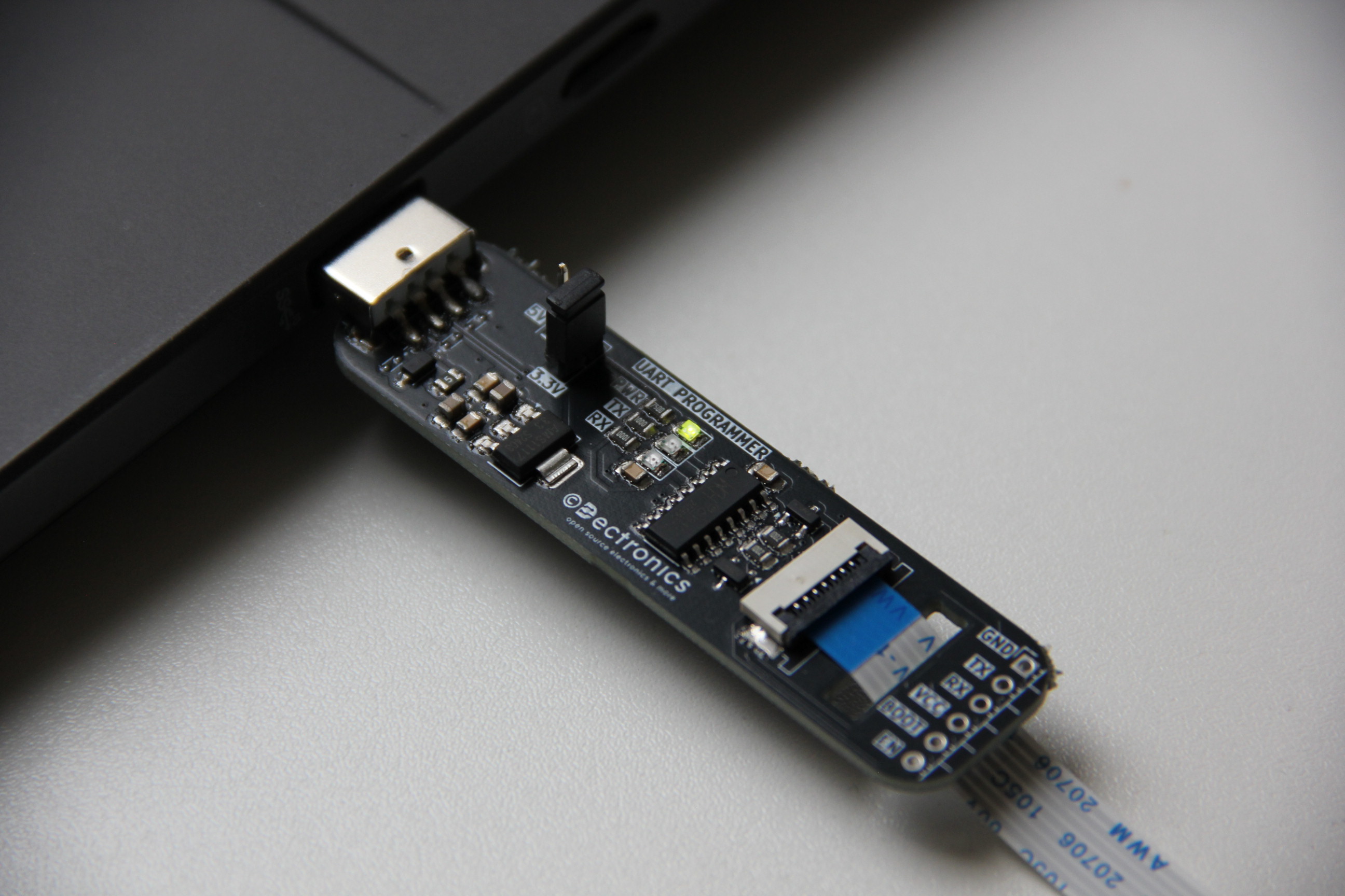
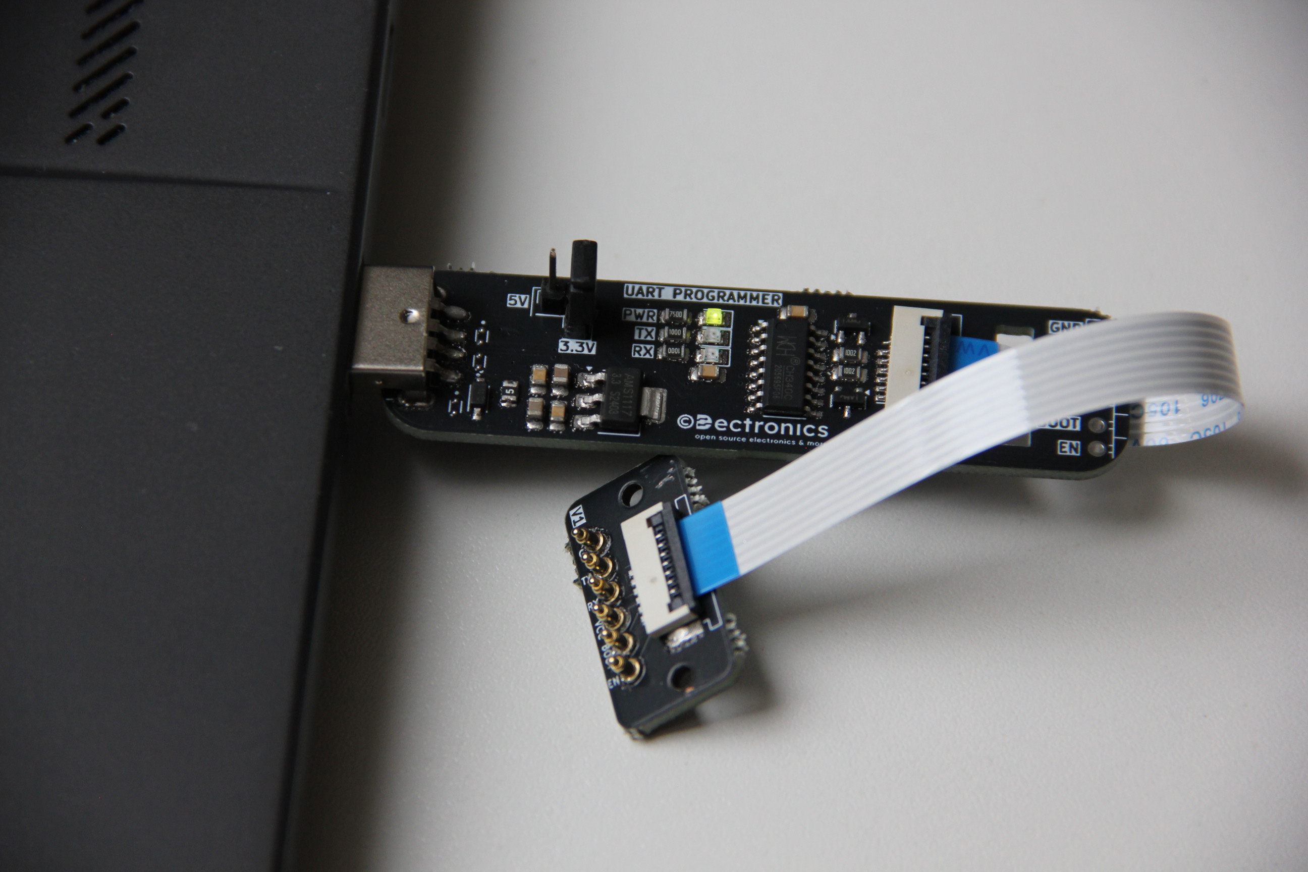
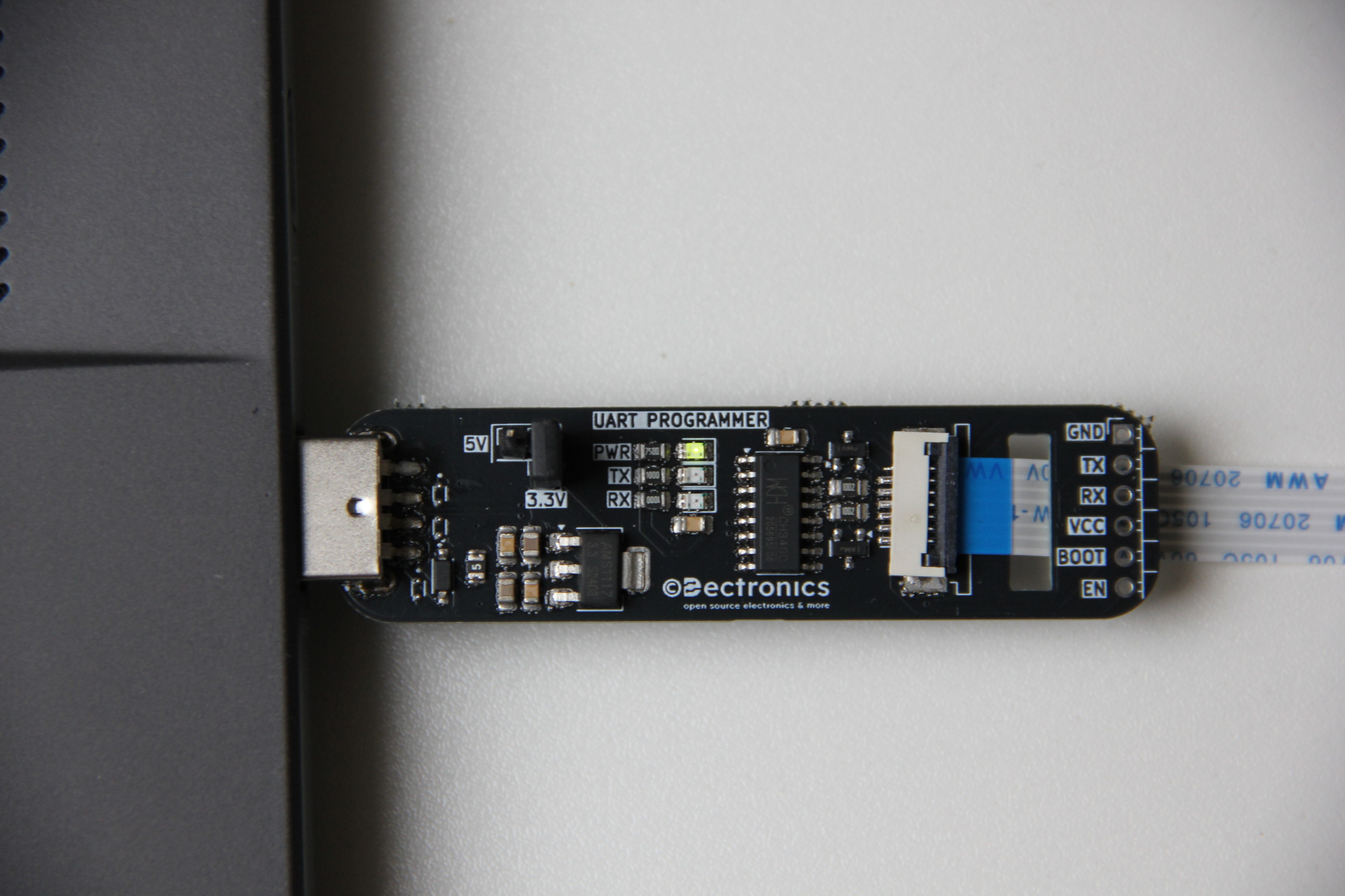
Driver Installation
Voltage Selection
Connection Methods
Method A: Direct Jumper Connections
Method B: External Programming Fixture
Programming
Status Monitoring
More Projects: Visit dectronics.cc for additional electronics projects
| Qty | Value | Footprint | References |
|---|---|---|---|
| 10 | Conn_01x01_Pin | Pogo-Pin 3.5mm:HARWIN_P70-1000045R | J5, J6, J7, J8, J9, J10, J11, J12, J13, J14 |
| 4 | MountingHole | MountingHole:MountingHole_2.2mm_M2 | H1, H2, H3, H4 |
| 3 | LED | LED_SMD:LED_0805_2012Metric | D1, D2, D3 |
| 3 | LESD5D5.0CT1G | LESD5D5.0CT1G:TVS_LESD5D5.0CT1G | D5, D6, D7 |
| 3 | LOGO | Drawings_Customs:Dectronics_Sub_12mm | G***, G***, G*** |
| 2 | 0.1uF | Capacitor_SMD:C_0805_2012Metric_Pad1.18x1.45mm_HandSolder | C4, C6 |
| 2 | 100nF | Capacitor_SMD:C_0805_2012Metric_Pad1.18x1.45mm_HandSolder | C1, C2 |
| 2 | 10kΩ | Resistor_SMD:R_0805_2012Metric_Pad1.20x1.40mm_HandSolder | R1, R2 |
| 2 | 10uF | Capacitor_SMD:C_0805_2012Metric_Pad1.18x1.45mm_HandSolder | C3, C5 |
| 2 | 1k | Resistor_SMD:R_0805_2012Metric | R4, R5 |
| 2 | Conn_01x06_MountingPin | Connector_FFC-FPC:TE_84953-6_1x06-1MP_P1.0mm_Horizontal | J3, J4 |
| 2 | MMBT3904 | Package_TO_SOT_SMD:SOT-23 | Q1, Q2 |
| 1 | 1N5819HW-7-F | 1N5819HW-7-F:SOD3715X145N | D4 |
| 1 | 750 | Resistor_SMD:R_0805_2012Metric | R3 |
| 1 | AMS1117-3.3 | Package_TO_SOT_SMD:SOT-223-3_TabPin2 | U2 |
| 1 | CH340C | Package_SO:SOIC-16_3.9x9.9mm_P1.27mm | U1 |
| 1 | Conn_01x06_Pin | Connector_PinHeader_2.54mm:PinHeader_1x06_P2.54mm_Horizontal | J2 |
| 1 | Conn_02x05_Odd_Even | Connector_IDC:IDC-Header_2x05_P2.54mm_Vertical | J19 |
| 1 | Fuse_Small | Fuse:Fuse_0805_2012Metric | F1 |
| 1 | Jumper_3_Open | test:VoltageJumper | JP1 |
| 1 | USB_A | Connector_USB:USB_A_CNCTech_1001-011-01101_Horizontal | J1 |
It measures 126.2 × 25.5 mm and has 2 copper layers, 1.6 mm thick.
46 parts, built around the CH340C, AMS1117-3.3, LESD5D5.0CT1G and MMBT3904. The full list of its parts is on this page, with links to each part's symbol and footprint where PCBKit's library has them.
From the TiebeDeclercq/Uart-programmer repository on GitHub, at the commit this page was made from: the board is Universal-Programmer/Universal-Programmer.kicad_pcb and its schematic Universal-Programmer/Universal-Programmer.kicad_sch. PCBKit opens the board in the browser, with nothing to install.
Its repository publishes it under the MIT licence: you may reuse it on that licence's terms (keep the author's notice, and for a copyleft licence share your changes alike).
AshiqAshref/Garage-Door-Opener
Universal Garage Door using BLE (Bluetooth Low Power) running on ESP32 with highest security possible.


paulmartinezcuenta/UltiCore-V1-PLC
Custom industrial-grade PLC and logic controller engineered around the ESP32 platform.


FrWA14/KiCad8_ESP32S3_DevModule_wroom-1_DevelopementBoard
Contient tout les fichier KiCad nécessaire pour faire une carte ESP32S3 avec un module Wroom-1.

shubhisgonnastealyourcode/FT-32-esp32-s3-dev-board-
Custom ESP32-S3 Development Board with Header Pins for Display and RGB LED
