
2 layers226.3 × 90.5 mm
Clockclock main
TiboDevC/clockclock
Personal project of a kinetic clock inspired by Humans Since 1982, using 48 stepper motors to display time in an artistic and dynamic way.
132 parts3GPL-3.0
 TiboDevC/clockclock3
Personal project of a kinetic clock inspired by Humans Since 1982, using 48 stepper motors to display time in an artistic and dynamic way.
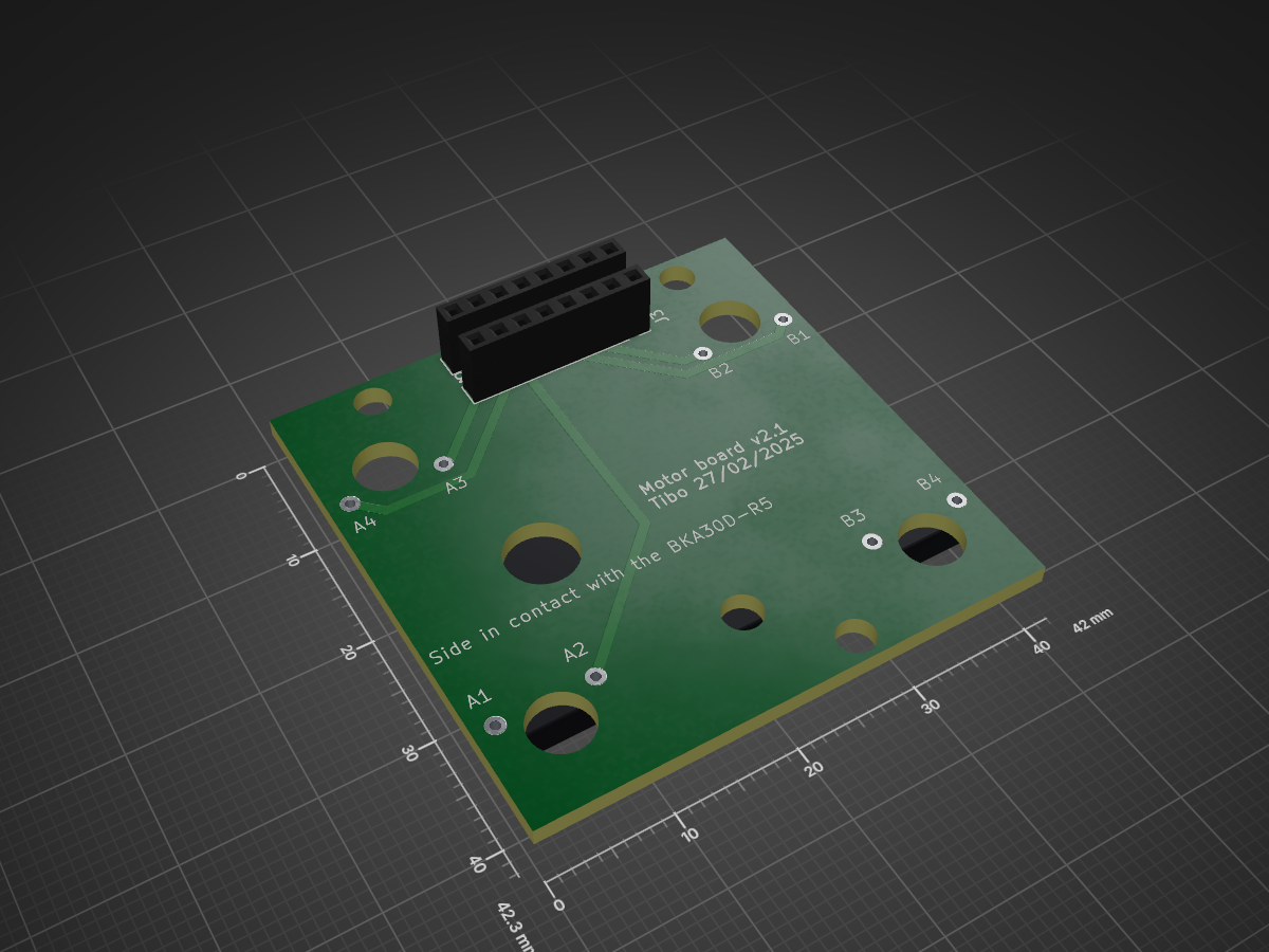
Clokclock stepper is an open-source printed circuit board by TiboDevC, from the TiboDevC/clockclock repository on GitHub, published under the GPL-3.0 licence. It is a 2-layer board of 42 × 42.3 mm with 3 parts on 8 nets, routed with 33 tracks and 0 vias.
It belongs with the robots and motor control boards of this library.
Personal project of a kinetic clock inspired by Humans Since 1982, using 48 stepper motors to display time in an artistic and dynamic way.
This project aims to create a kinetic clock with the following constraints:
The ClockClock architecture is built around a highly efficient, centralized control system that manages all 48 stepper motors from a single ESP32-C3 microcontroller. This approach contrasts with typical multi-motor projects that require multiple microcontrollers or complex distributed systems.
ESP32-C3 → TPIC6C595 Shift Registers (×12) → VID6606 Motor Drivers (×12) → BKA30D-R5 Motors (×48)
   ↓                    ↓                              ↓                           ↓
 3 GPIO              96 bits                    2 signals per motor         2 bits per motor
pins (SPI @ 10MHz) (STEP + DIR) (individual control)Minimal GPIO Usage: The entire system uses only 3 GPIO pins (MOSI, SCK, SS) thanks to the shift register cascade. This leaves the ESP32-C3's remaining pins available for other peripherals (I2C for RTC, buttons, encoder, etc.).
Serial-to-Parallel Conversion: The 12 cascaded TPIC6C595 shift registers convert the serial SPI data stream into 96 parallel outputs. Each motor requires 2 control bits (STEP and DIR), allowing precise control of all 48 motors simultaneously.
Hierarchical Organization:
Data Flow Pipeline:
Time/Animation Logic → Motor Position Calculation → SPI Data Preparation →
Hardware SPI Transfer (10µs) → Parallel Latch → Simultaneous Motor Update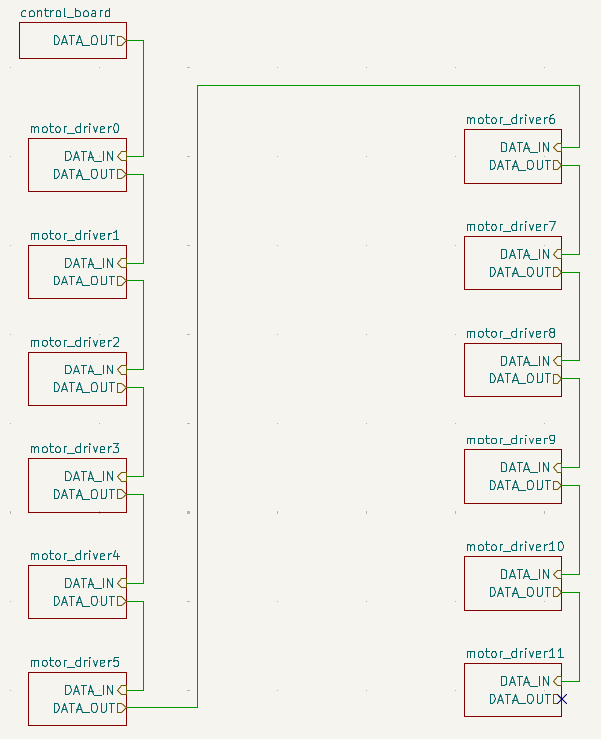 All motor blocks are linked together
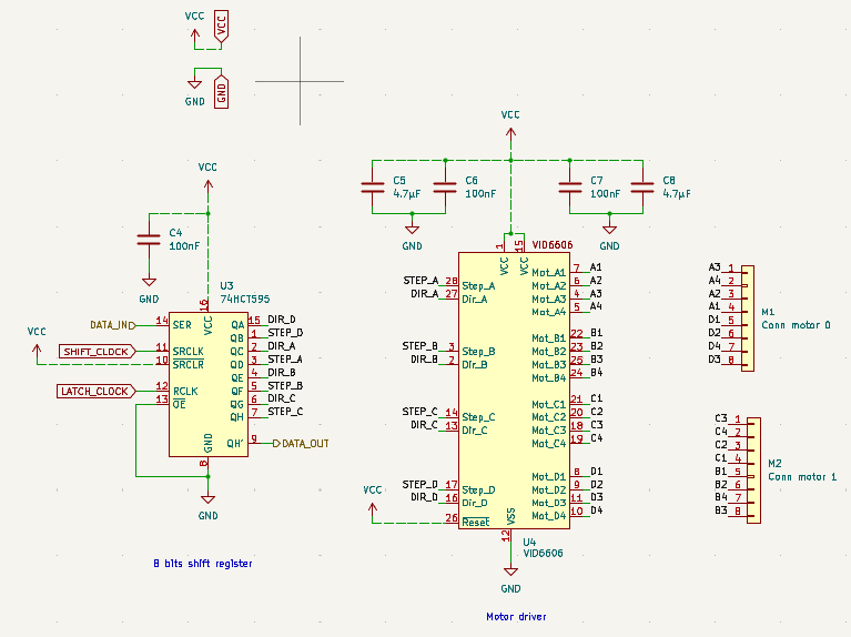 A motor block
Features:
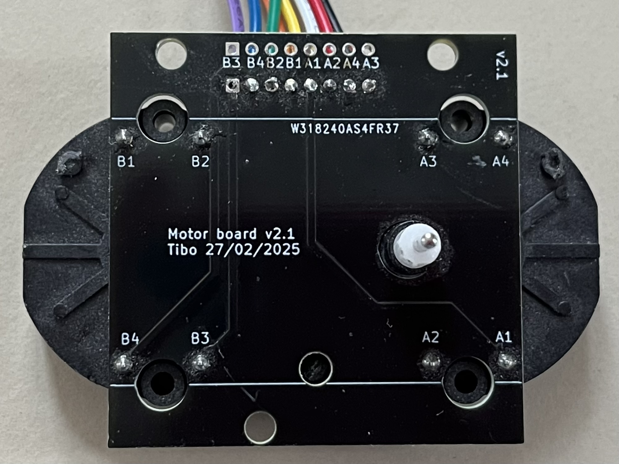
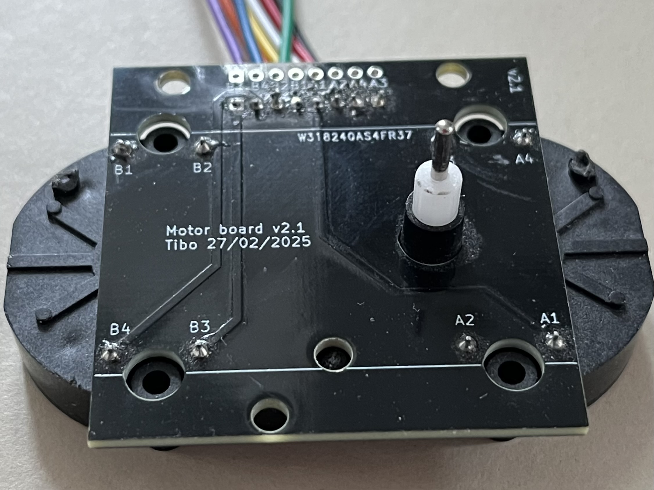
The motor itself with its PCB to connect to the motor driver
Each VID6606 driver (or equivalent AX1201728SG/STI6606z) can control 4 motors with only 2 signals per motor:
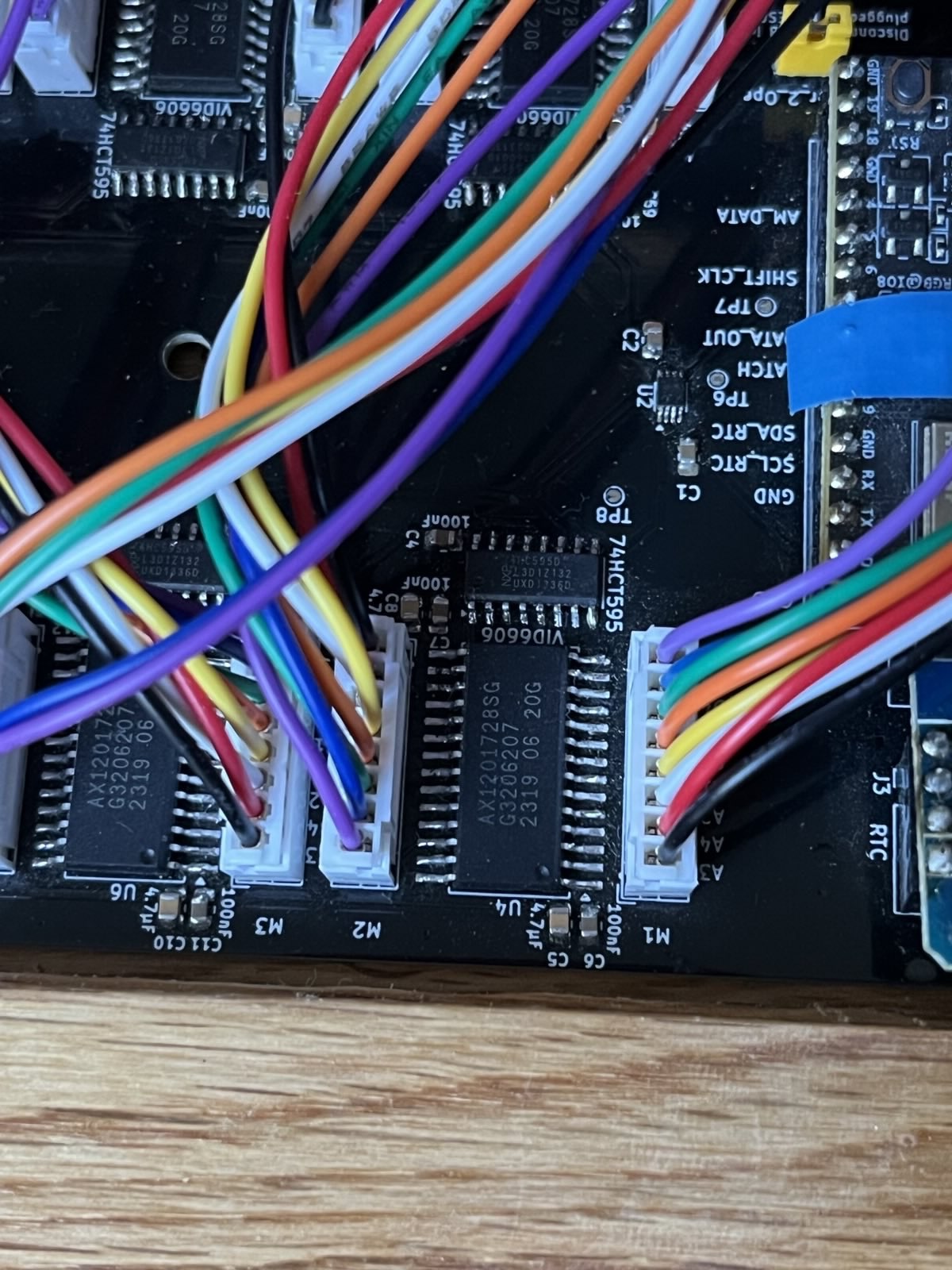
The AX1201728SG driver is connected to 4 motors (the two connectors on its right and left). On top, the shift register
Key Advantages:
The firmware implements European rules:
Files: elec/clockclock_main/ → PDF Schematic
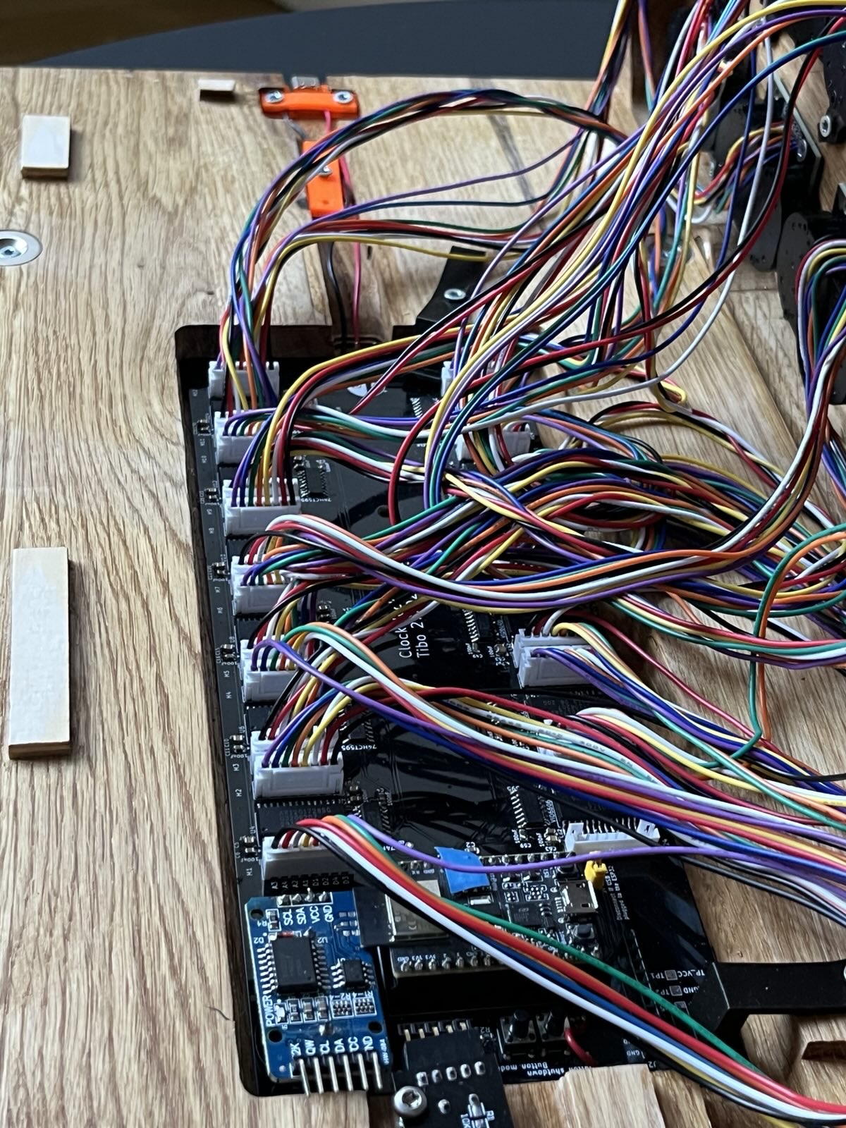
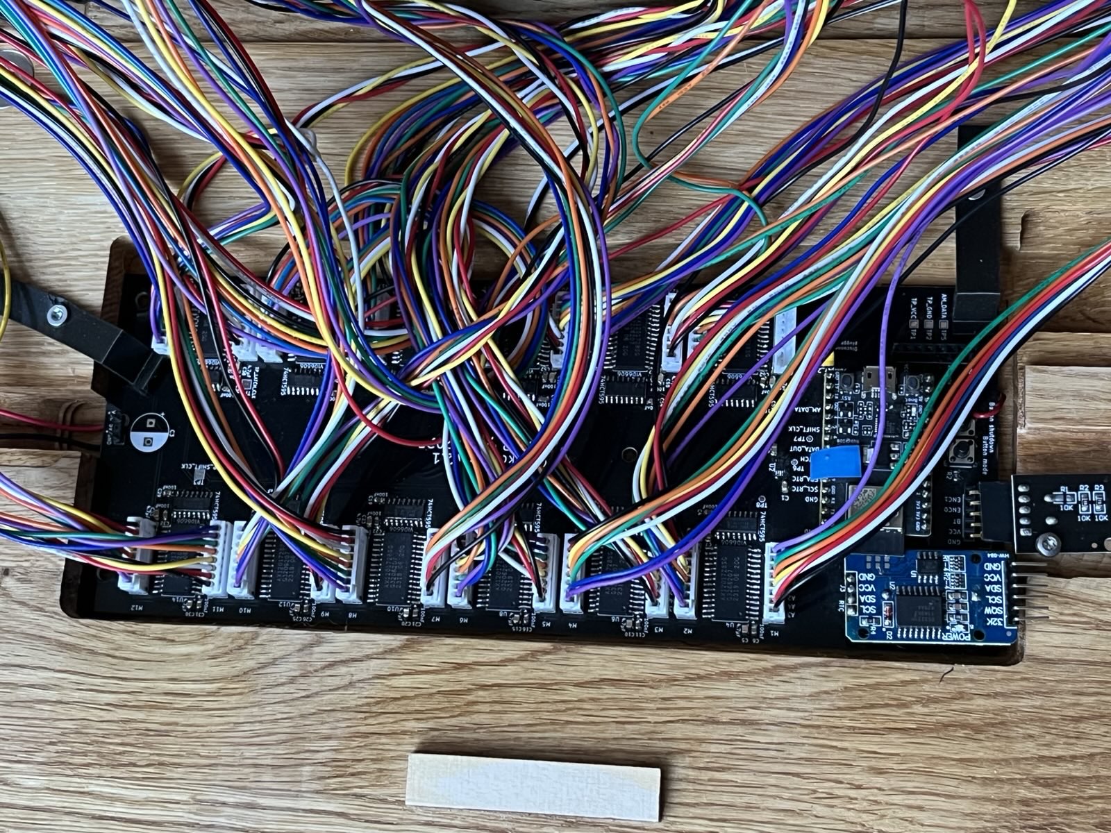
Main board fully wired
Clock starts
| Component | Reference | Quantity | Function |
|---|---|---|---|
| Microcontroller | ESP32-C3-DevKitM-1 | 1 | Central control (RISC-V) |
| Shift Registers | TPIC6C595 | 12 | Output expansion |
| Motor Drivers | VID6606 / AX1201728SG | 12 | 4 motors per driver |
| RTC | DS3231 | 1 | Real-time clock |
| Radio Receiver | DCF77 CANADUINO | 1 | Atomic sync |
Buttons:
Rotary Encoder:
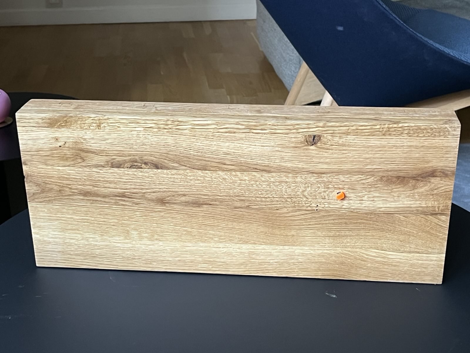 Only one button is connected (the orange button here), and it is used to enter the "shutdown" mode
Files: elec/clokclock_stepper/ → PDF Schematic
Each board is very simple and connects a BKA30D-R5 motor to its VID6606 driver.
Total: 24 identical motor boards
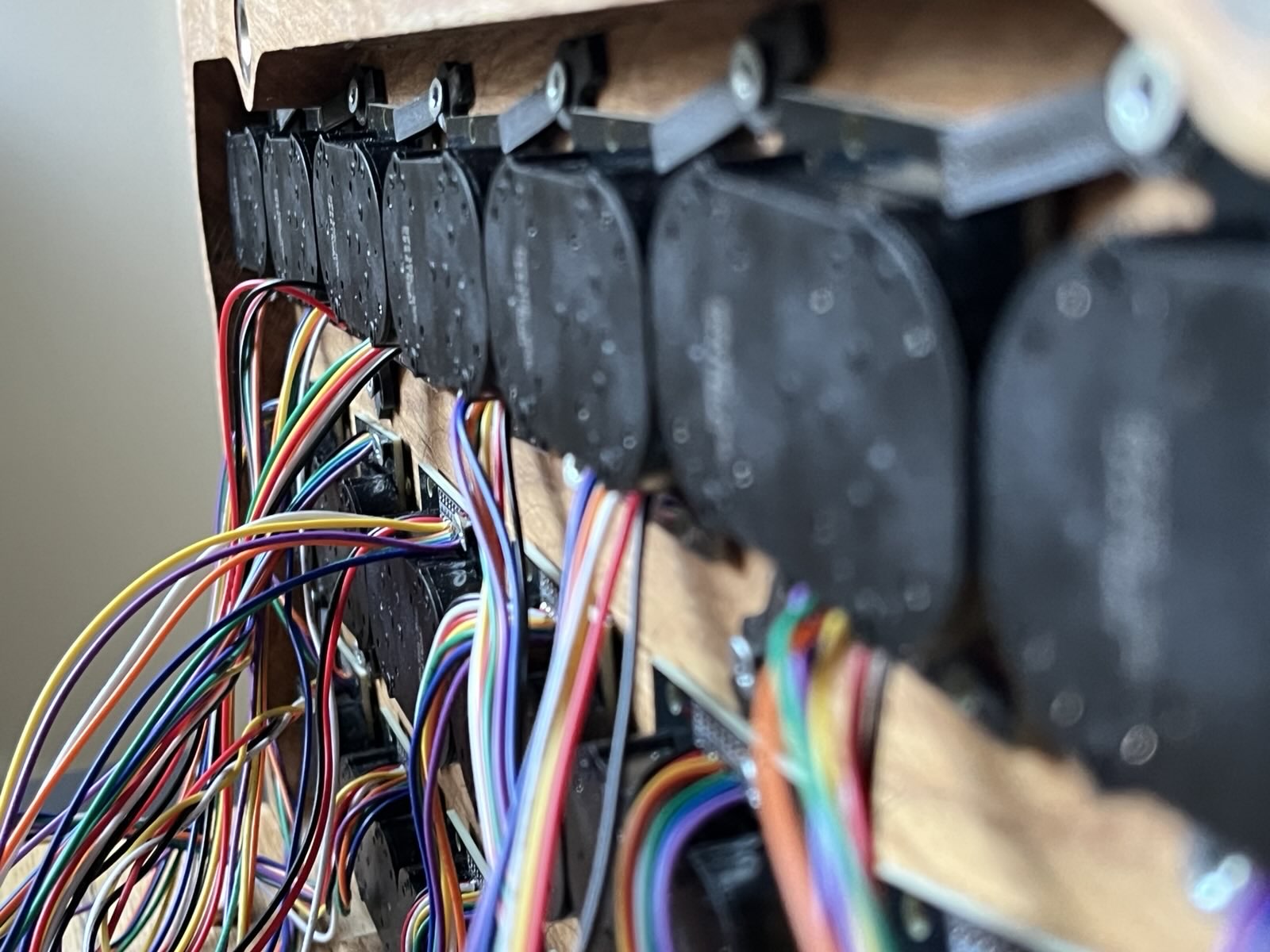 Row of motors mounted on the main frame
This is the part that took most of the design time! I tried many different materials and manufacturing methods before settling on laser-cut acrylic hands.
The challenge is to be able to manufacture hands that can be unmounted/remounted easily and that fit perfectly on the
motor shaft.
In addition, the hands should be as close together as possible in order to maintain a good viewing angle when looking at
the clock from the side.
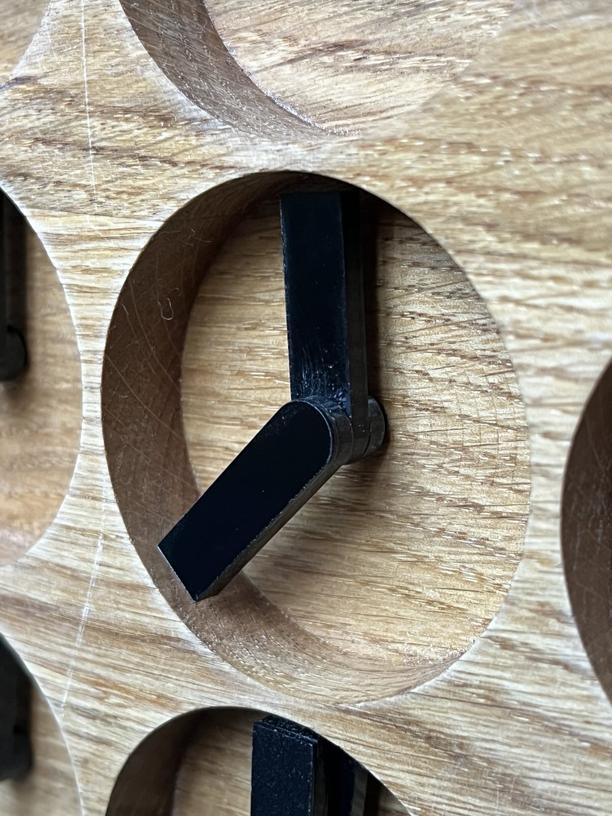
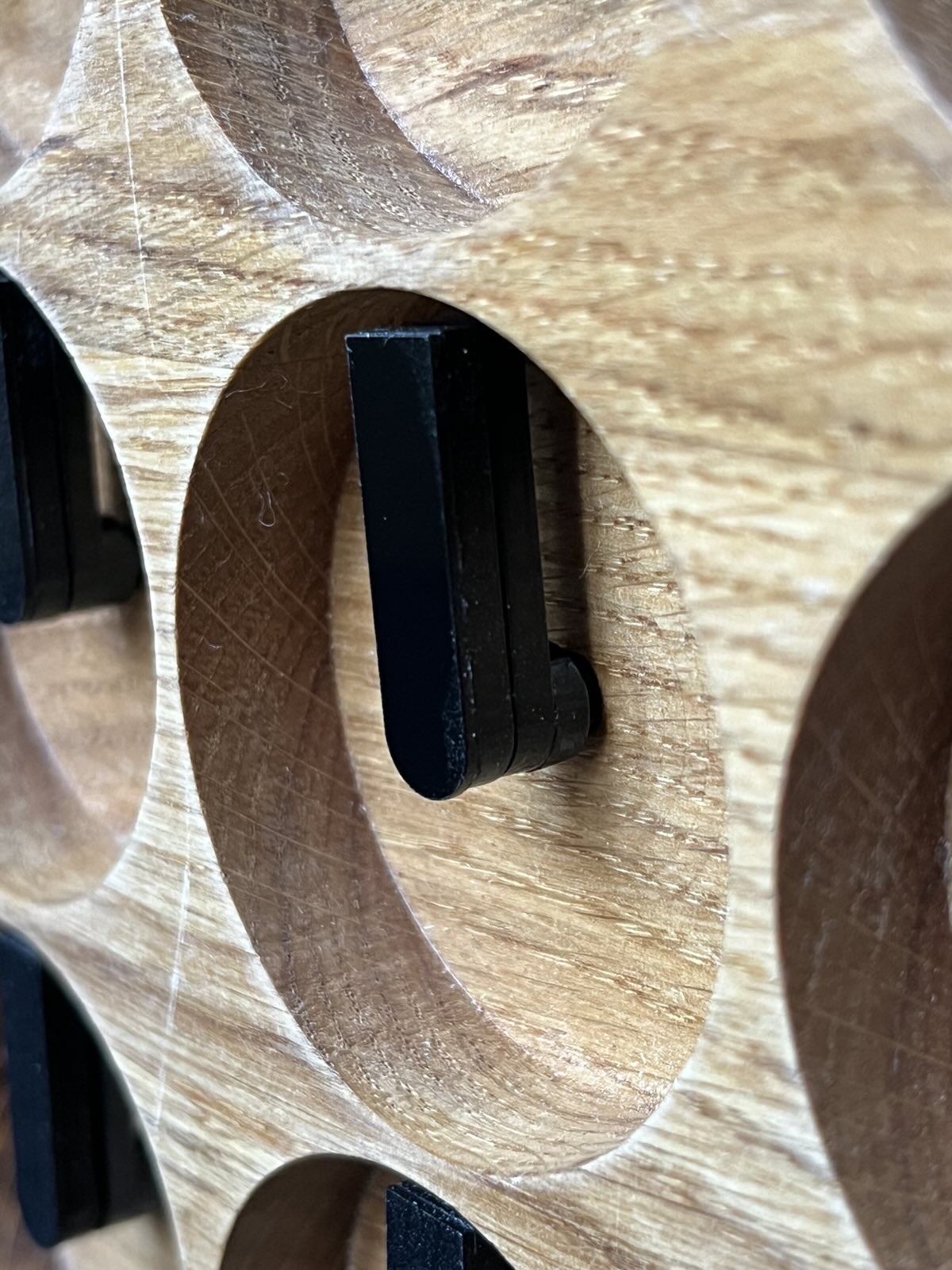
Mounted hands
Here is the final solution I adopted:
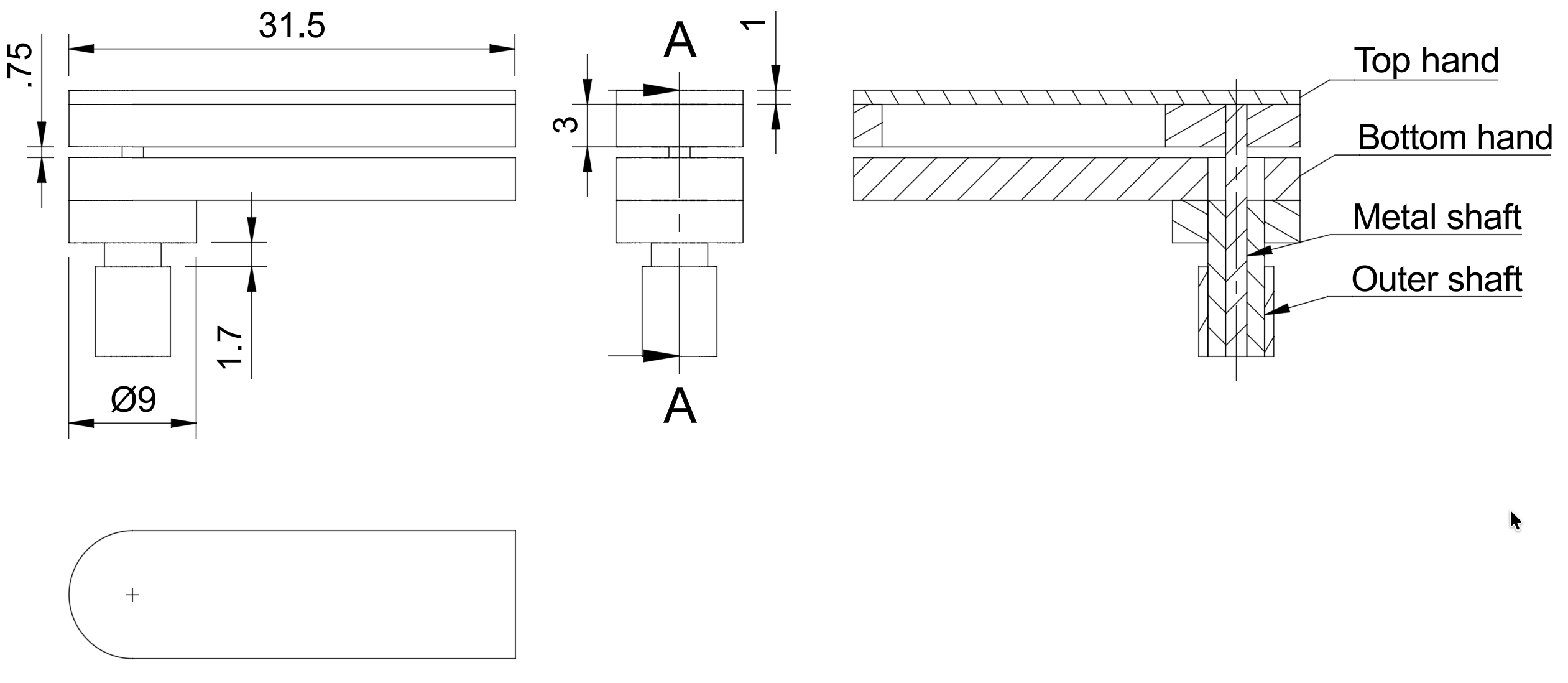 Hands assembly
Both the top and bottom hands are in two acrylic parts glued together.
The top one as a 1mm acrylic part glued to a 3mm part that fits on the motor shaft.
The bottom one is a 3mm part glued to a 3mm part that fits on the motor shaft.
firmware/
├── platformio.ini          # Project configuration
├── include/
│   └── cfg.hpp            # Global constants (motors count, pins, etc.)
└── src/
    ├── main.cpp           # Entry point
    ├── time_manager.*     # Time management and DST
    ├── ntp_sync.*         # Optional NTP sync (dev only)
    ├── animation/         # Animation system
    │   ├── animation_manager.*
    │   ├── wave_animation.*
    │   └── sync_rotation_animation.*
    ├── button/            # Button and encoder handling
    │   └── button.*
    ├── mode/              # Operating modes
    │   ├── mode.*
    │   ├── calibration.*
    │   └── cfg_time.*
    └── motor/             # Motor control
        ├── motor_motion.* # Mapping and sequences
        ├── motion.*       # Display logic
        ├── shift_register.* # SPI interface
└── AccelStepper.* # Movement libraryThe firmware implements several operation modes:
The AnimationManager enables choreographed animations:
Available Animations:
Triggering:
PlatformIO dependencies:
NorthernWidget/DS3231@1.1.2: RTC interfacearduino-libraries/NTPClient@^3.2.1: Optional NTP sync# Install PlatformIO CLI
pip install platformio
# Or via VSCode: Install "PlatformIO IDE" extensioncd firmware/
pio run# Via USB
pio run --target upload
# Serial monitor
pio device monitorTo enable NTP sync during development, enable NTP_WIFI_SYNC define in main.cpp and configure your WiFi credentials.
Note: In production, WiFi is not required thanks to the DCF77 module.
Motor speed and acceleration can be adjusted in firmware/src/motor/motor_motion.cpp.
The firmware is configured for Central European Time (CET/CEST) by default. To change timezone, modify the DST
configuration in main.cpp.
| Document | Path | Format |
|---|---|---|
| Main board schematic | elec/clockclock_main/output/clockclock_main.pdf | |
| Main board PCB | elec/clockclock_main/clockclock_main.kicad_pcb | KiCad |
| Motor board schematic | elec/clokclock_stepper/output/clokclock_stepper.pdf | |
| Motor board PCB | elec/clokclock_stepper/clokclock_stepper.kicad_pcb | KiCad |
| Driver test board | elec/test_board_motor_driver/ | KiCad |
All datasheets are available in the datasheet/ folder:
The code includes conditional debug flags that can be enabled in respective source files:
DEBUG - General messagesDEBUG_MOTION - Motor control debugDEBUG_TIME_MGMT - Time management debugDEBUG_ANIMATION - Animation debugDEBUG_MODE - Mode debugGit pre-commit configuration available: .pre-commit-config.yaml
pip install -r requirements.txt
pre-commit installThis project is open-source. Free to use and modify.
Inspired by the artistic work of Humans Since 1982.
| Qty | Value | Footprint | References |
|---|---|---|---|
| 2 | Conn_01x08 | Connector_PinSocket_2.00mm:PinSocket_1x08_P2.00mm_Vertical | J3, J4 |
| 1 | ~ | perso:BKA30D-R5 | BKA30D-R1 |
It measures 42 × 42.3 mm and has 2 copper layers, 1.6 mm thick.
3 parts. The full list of its parts is on this page, with links to each part's symbol and footprint where PCBKit's library has them.
From the TiboDevC/clockclock repository on GitHub, at the commit this page was made from: the board is elec/clokclock_stepper/clokclock_stepper.kicad_pcb and its schematic elec/clockclock_main/clockclock_main.kicad_sch. PCBKit opens the board in the browser, with nothing to install.
Its repository publishes it under the GPL-3.0 licence: you may reuse it on that licence's terms (keep the author's notice, and for a copyleft licence share your changes alike).
TiboDevC/clockclock
Personal project of a kinetic clock inspired by Humans Since 1982, using 48 stepper motors to display time in an artistic and dynamic way.

TiboDevC/clockclock
Personal project of a kinetic clock inspired by Humans Since 1982, using 48 stepper motors to display time in an artistic and dynamic way.


hzeller/rpi-rgb-led-matrix
Controlling up to three chains of 64x64, 32x32, 16x32 or similar RGB LED displays using Raspberry Pi GPIO


atopile/atopile
Design circuit boards with code! ✨ Get software-like design reuse 🚀, validation, version control and collaboration in hardware; starting with electronics ⚡️


hackclub/sprig
🍃 Learn to code by making games in a JavaScript web-based game editor.