
4 layers137 × 79.5 mm

 tiband/Tiband-BitConnector
This is the Tiband version of the BitConnector, a Xilinx XC9572XL CPLD board for breadboard prototyping
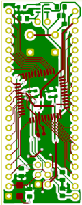
BitConnector is an open-source printed circuit board by tiband, from the tiband/Tiband-BitConnector repository on GitHub. It is a 2-layer board of 21.1 × 53.3 mm with 24 parts on 46 nets, routed with 358 tracks and 20 vias.
It is built around the 74LVC2G14GW. Its parts include 7 capacitors, 7 resistors, 3 connectors, 2 ICs and 1 diode. It belongs with the fPGA and programmable logic boards and the FPGA and CPLD boards of this library.
The BitConnector is a Complex Programmable Logic Device (CPLD) Board, optimized for hardware-based, digital prototype design on a breadboard. The BitConnector is designed to represent a classic DIP chip in 2.54mm pitch with 2 * 20 pins. Configurations that are present in an HDL/schematic are transmitted via JTAG and stored permanently on the CPLD.
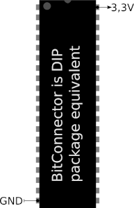 | 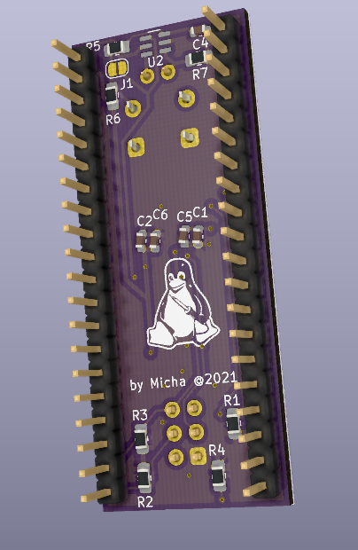 | 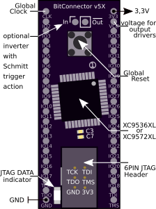 | 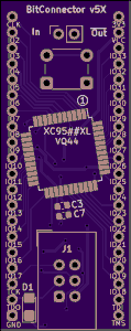 |  |
| No | DIP-left | CPLD-Pin | comment | DIP-right | CPLD-Pin | comment |
| 1 | CLK | 1 | GCK3 | 3V3 | 15,35 | VccINT |
| 2 | IO2 | 2 | VCC | 26 | VccIO | |
| 3 | IO3 | 3 | IO33 | 44 | GCK2 | |
| 4 | IO4 | 5 | IO32 | 43 | GCK1 | |
| 5 | IO5 | 6 | IO31 | 42 | ||
| 6 | IO6 | 7 | IO30 | 41 | ||
| 7 | IO7 | 8 | IO29 | 40 | ||
| 8 | IO8 | 12 | IO28 | 39 | ||
| 9 | IO9 | 13 | IO27 | 38 | ||
| 10 | IO10 | 14 | IO26 | 37 | ||
| 11 | IO11 | 16 | IO25 | 36 | GTS1 | |
| 12 | IO12 | 18 | IO24 | 34 | GTS2 | |
| 13 | IO13 | 19 | IO23 | 32 | ||
| 14 | IO14 | 20 | IO22 | 31 | ||
| 15 | IO15 | 21 | IO21 | 30 | ||
| 16 | IO16 | 22 | IO20 | 29 | ||
| 17 | IO17 | 23 | IO19 | 28 | ||
| 18 | TCK | 11 | JTAG | IO18 | 27 | |
| 19 | TDO | 24 | JTAG | TDI | 9 | JTAG |
| 20 | GND | 17,25,4 | TMS | 10 | JTAG |
Supplements and notes:
| No | component | value | quantity | package |
| 1 | Unpolarized capacitor | 100nF | 3 | 0603 |
| 2 | Unpolarized capacitor | 10nF | 3 | 0603 |
| (3) | Unpolarized capacitor | 100nF | 1 | 0603 |
| (4) | Resistor | 100K | 1 | 0805 |
| (5) | Resistor | 10K | 1 | 0805 |
| 6 | Resistor | 10K | 4 | 0805 |
| 7 | Resistor | 120 | 1 | 0805 |
| 8 | LED | blue | 1 | 1206 |
| 9 | Push button | 6 mm | 1 | THT |
| 10 | Pin Header 1x20 | 2.54 mm | 2 | vertical |
| (11) | 74LVC2G14 | Schmitt-Tr | 1 | SOT457 |
| 12 | XC9536XL/XC9572XL | CPLD | 1 | VQ44/VQG44 |
This project by Michael Krause is distributed in the hope that it will be useful, but WITHOUT ANY WARRANTY.
This project is free: you can redistribute it and/or modify it under the terms of CC BY-SA 4.0 Excluded from this licence is the logo(./doc/Figures/Logo.pdf). Should you change or delete something, please remove the logo.
| Qty | Value | Footprint | References |
|---|---|---|---|
| 5 | 10K | Resistor_SMD:R_0805_2012Metric_Pad1.20x1.40mm_HandSolder | R1, R2, R3, R6, R7 |
| 4 | 100nF | Capacitor_SMD:C_0603_1608Metric | C1, C2, C3, C4 |
| 3 | 10nF | Capacitor_SMD:C_0603_1608Metric | C5, C6, C7 |
| 2 | Conn_01x20 | Connector_PinHeader_2.54mm:PinHeader_1x20_P2.54mm_Vertical | DIP_20_l1, DIP_20_r1 |
| 1 | 100K | Resistor_SMD:R_0805_2012Metric_Pad1.20x1.40mm_HandSolder | R5 |
| 1 | 120 | Resistor_SMD:R_0805_2012Metric_Pad1.20x1.40mm_HandSolder | R4 |
| 1 | 74LVC2G14 | Package_SO:SC-74-6_1.5x2.9mm_P0.95mm | U2 |
| 1 | Conn_01x02 | Connector_PinSocket_2.54mm:PinSocket_1x02_P2.54mm_Vertical | J2 |
| 1 | JTAG | Connector_IDC:IDC-Header_2x03_P2.54mm_Vertical | J1 |
| 1 | LED_blue | LED_SMD:LED_1206_3216Metric_Castellated | D1 |
| 1 | LOGO | logo:tux_logo | G*** |
| 1 | XC95##XL-VQ44 | Package_QFP:LQFP-44_10x10mm_P0.8mm | U1 |
| 1 | disable_schmitt_trigger_action | Jumper:SolderJumper-2_P1.3mm_Open_RoundedPad1.0x1.5mm | J1 |
| 1 | reset | Button_Switch_THT:SW_PUSH_6mm | SW1 |
It measures 21.1 × 53.3 mm and has 2 copper layers, 1.46 mm thick.
24 parts, built around the 74LVC2G14GW. The full list of its parts is on this page, with links to each part's symbol and footprint where PCBKit's library has them.
From the tiband/Tiband-BitConnector repository on GitHub, at the commit this page was made from: the board is BitConnector.kicad_pcb. PCBKit opens the board in the browser, with nothing to install.
Its repository states no licence, so its author keeps all rights: ask tiband before reusing the design.


skumlos/bkm-10rlternative
Project aiming to replicate the BKM-10R/11R remote for Sony professional CRT monitors.

Mr-Bossman/SD_Swap
A development tool which swaps an sdcard between a usb3 card reader or a SBC.

mikelawrence/WiFi-Gate-Controller
WiFi enabled Gate Controller Addon to US Automatic Gate Opener

mikelawrence/WiFi-Septic-Controller
WiFi enabled Septic Controller

