4 layers137 × 79.5 mm

 tadas-s/OSC2Midi34
ESP8266 based OSC <-> MIDI WiFi bridge
Esp8266-midi is an open-source printed circuit board by tadas-s, from the tadas-s/OSC2Midi repository on GitHub, published under the MIT licence. It is a 2-layer board of 75 × 82 mm with 33 parts on 23 nets, routed with 151 tracks and 17 vias.
It is built around the ESP-12E and 74LVC2G14GW. Its parts include 10 resistors, 7 connectors, 5 capacitors, 5 ICs and 1 diode. It belongs with the audio and music and radio and wireless boards and the ESP8266 boards of this library.


ESP8266 based OSC <-> Midi wireless bridge.
It is mostly meant to be used with TouchOSC but it will work with any OSC message source.
Project uses:
Based on a generic ESP8266-12f board and the following guides to hook up ESP8266 and do MIDI i/o:
Midi I/O uses SoftwareSerial mostly to allow debug logging via primary serial port.
Note! Do checkout the KiCad project instead. Image below is for quick preview only.
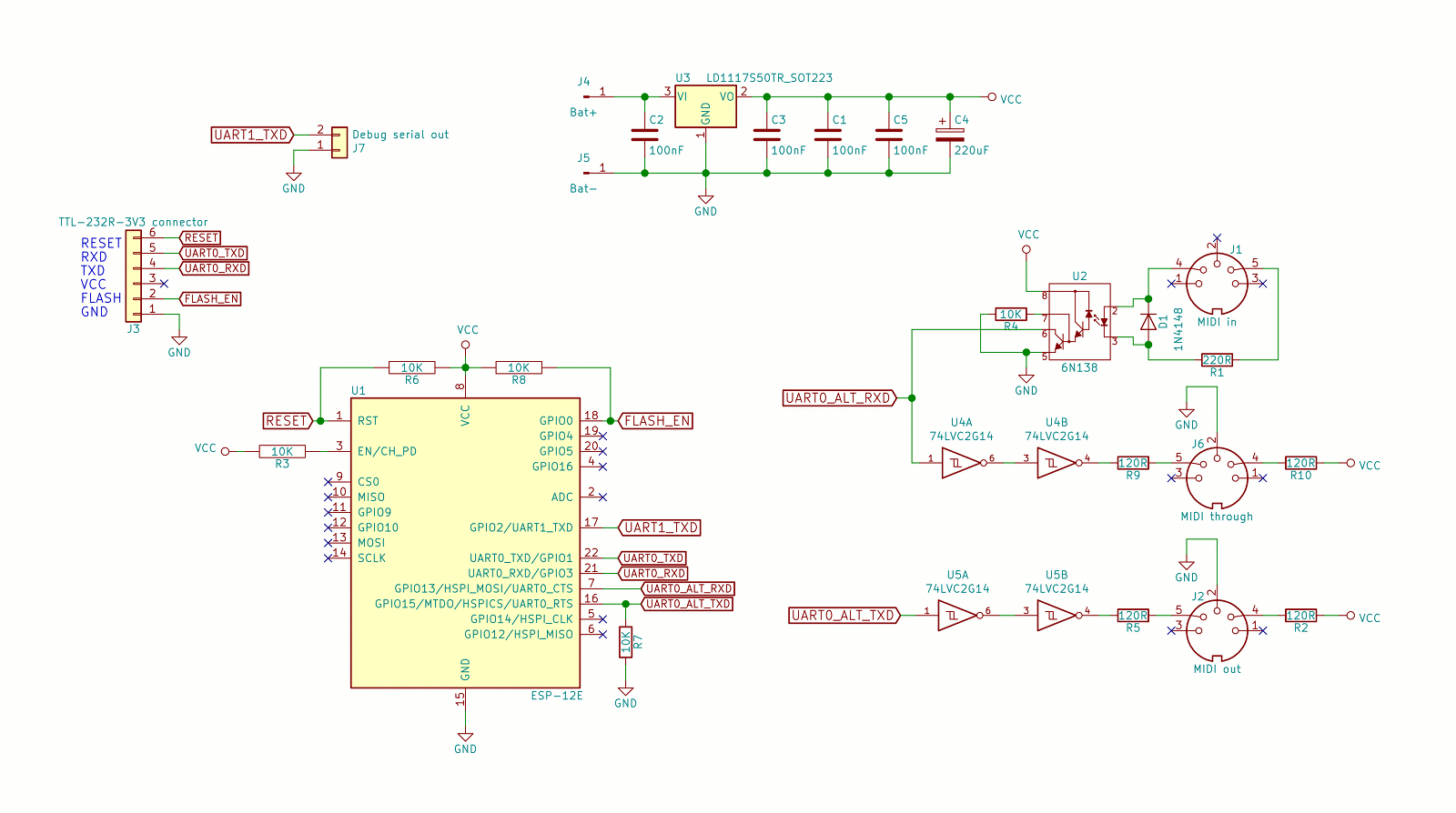
To flash the firmware I'm using FTDI cable with flash+reset circuit.
All messages are expected to have payload of 1 or 2 floats with range from 0 to 127.
Will send control change message for {cc} number.
Will send control change message for CC specified by {index}. For
example:
This is meant to be used with TouchOSC groups of faders. For example,
my MicroKORG preset includes a fader group of 4 to control
amp ADSR: /midi/cc/73/75/70/72
This sends two control change messages to {ccA} and {ccB}. This is
meant to be used with TouchOSC XY pads.
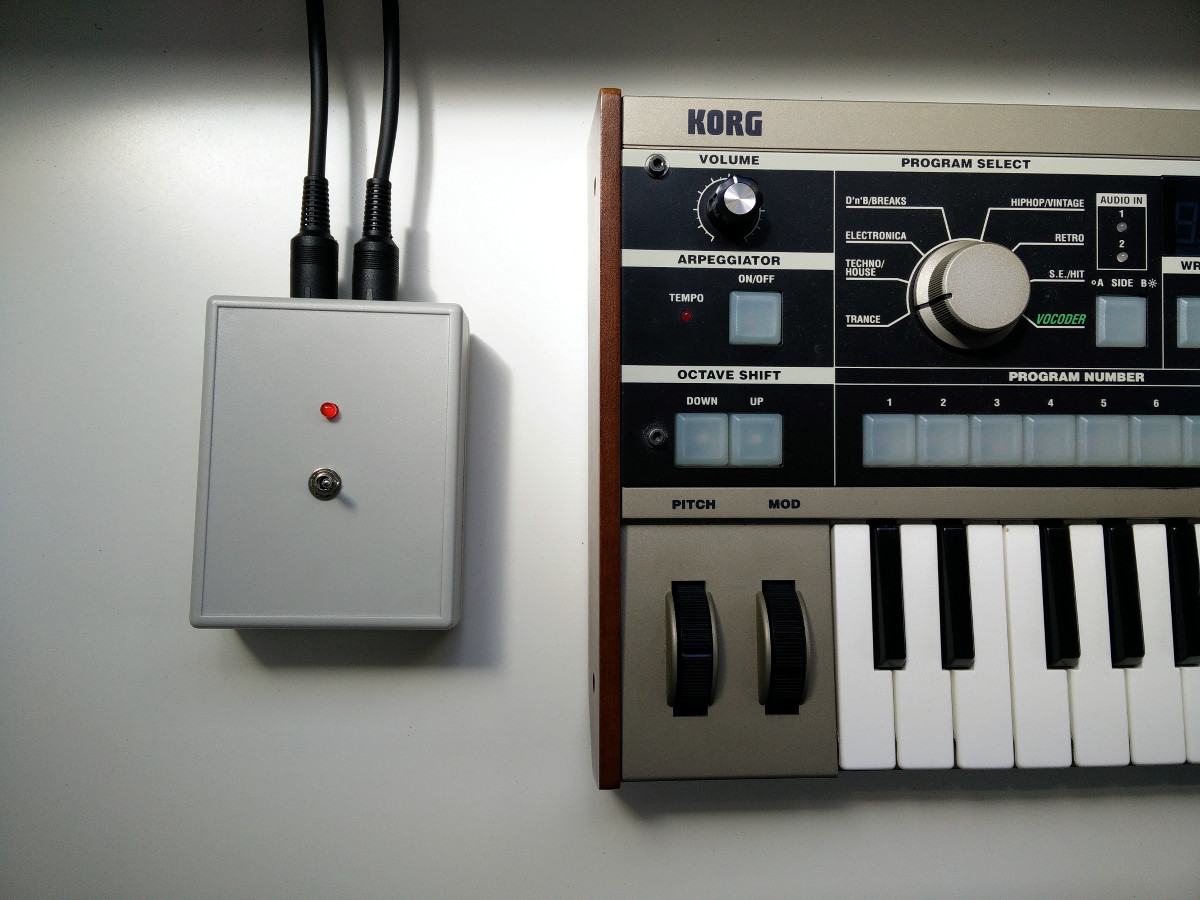
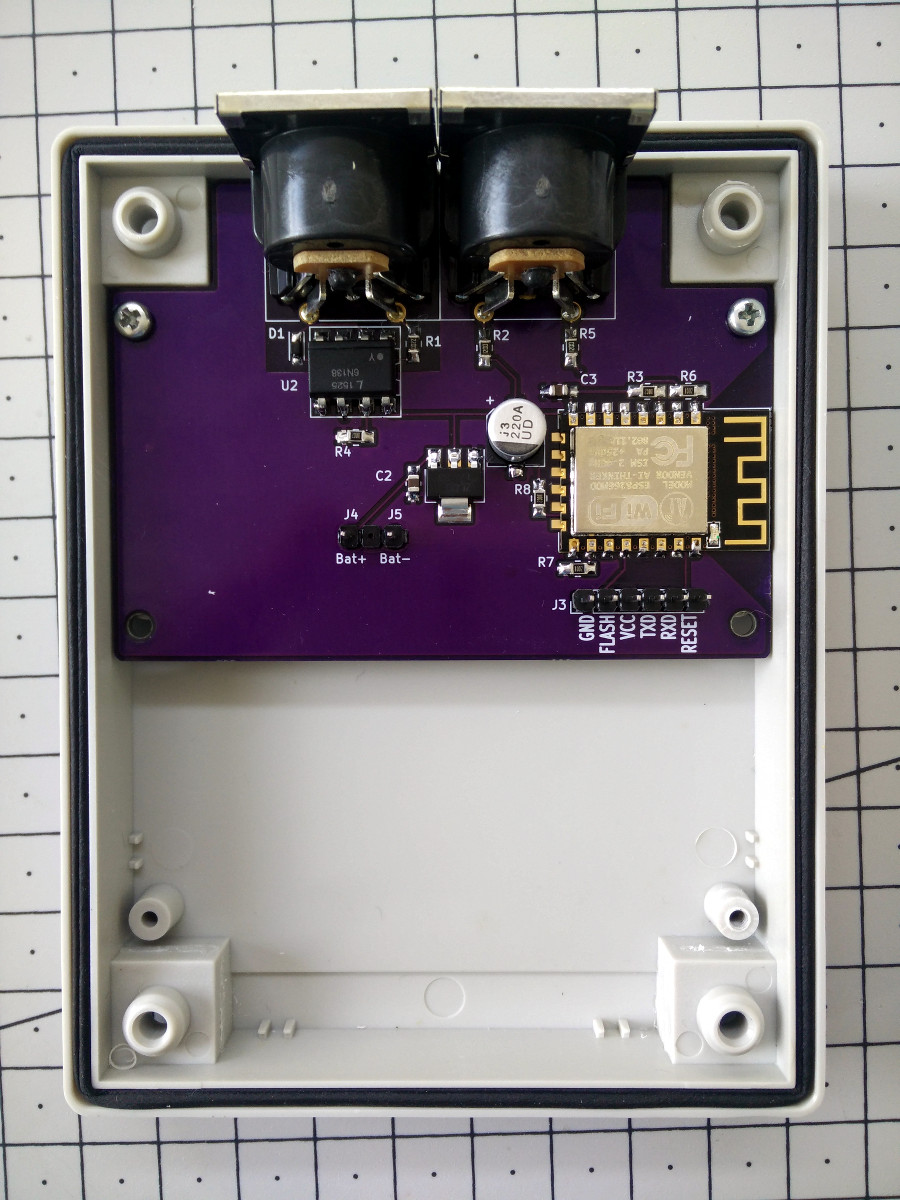
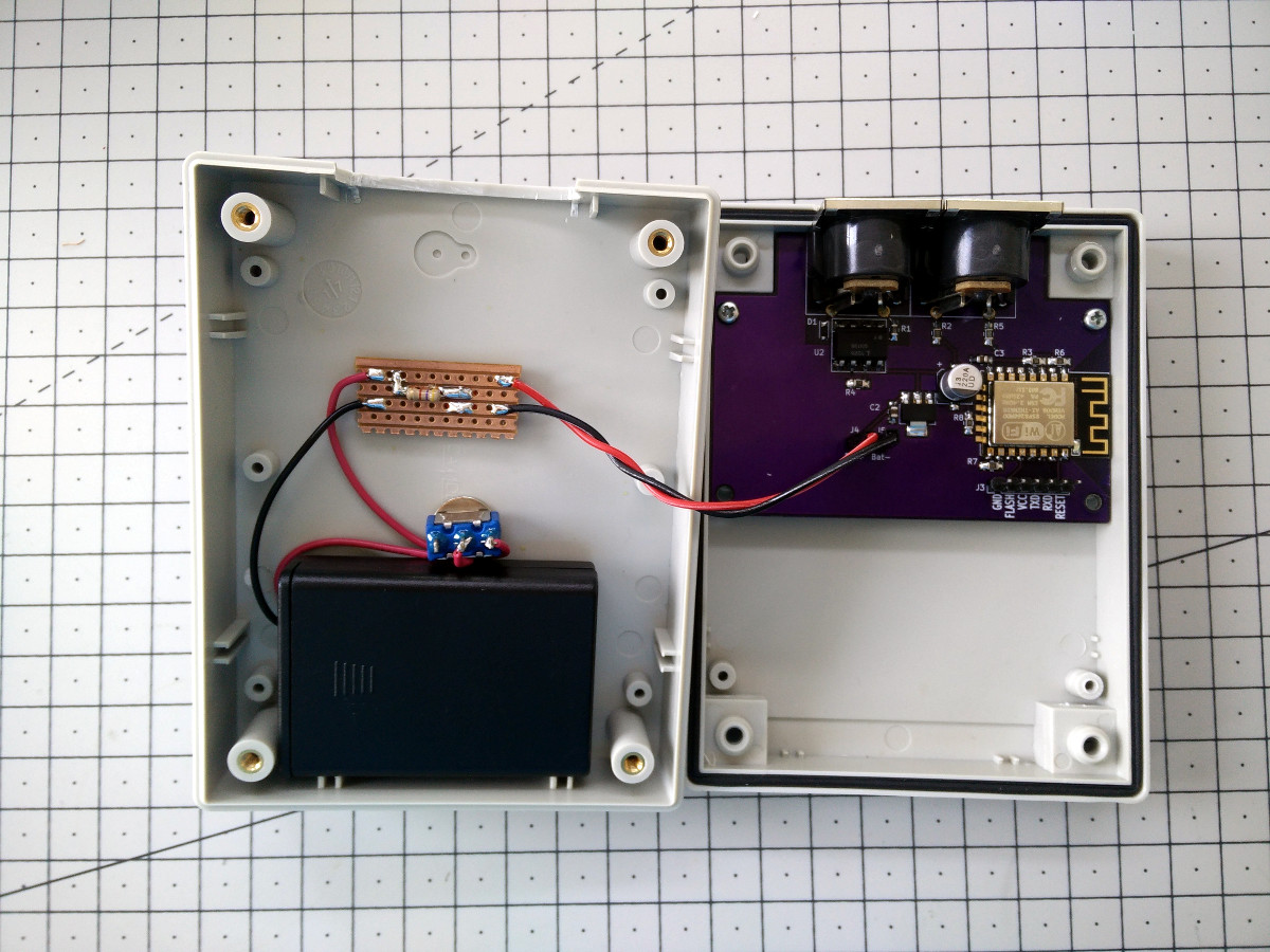
Rather crude build, but it works:
So it seems GitHub is about to take a snapshot of active open source repositories and put it into cold storage that should last 1000 years. Hence this section: a change for the sake of it. Exact criteria is not clear, but hope this repository makes it to the archive.
| Qty | Value | Footprint | References |
|---|---|---|---|
| 5 | Mounting_Holes:MountingHole_2.7mm_M2.5 | , , , , | |
| 5 | 10K | Resistors_SMD:R_0805_HandSoldering | R3, R4, R6, R7, R8 |
| 4 | 100nF | Capacitors_SMD:C_0805_HandSoldering | C1, C2, C3, C5 |
| 4 | 120R | Resistors_SMD:R_0805_HandSoldering | R2, R5, R9, R10 |
| 2 | 74LVC2G14 | TO_SOT_Packages_SMD:SOT-23-6_Handsoldering | U4, U5 |
| 1 | 1N4148 | Diodes_SMD:D_SOD-323_HandSoldering | D1 |
| 1 | 220R | Resistors_SMD:R_0805_HandSoldering | R1 |
| 1 | 220uF | Capacitors_SMD:CP_Elec_6.3x5.8 | C4 |
| 1 | 6N138 | Housings_DIP:DIP-8_W7.62mm_SMDSocket_SmallPads | U2 |
| 1 | Bat+ | Wire_Pads:SolderWirePad_single_0-8mmDrill | J4 |
| 1 | Bat- | Wire_Pads:SolderWirePad_single_0-8mmDrill | J5 |
| 1 | Debug serial out | Pin_Headers:Pin_Header_Straight_1x02_Pitch2.54mm | J7 |
| 1 | ESP-12E | RF_Modules:ESP-12E | U1 |
| 1 | LD1117S50TR_SOT223 | TO_SOT_Packages_SMD:SOT-223 | U3 |
| 1 | MIDI in | Connectors:SDS-50J | J1 |
| 1 | MIDI out | Connectors:SDS-50J | J2 |
| 1 | MIDI through | Connectors:SDS-50J | J6 |
| 1 | TTL-232R-3V3 connector | Pin_Headers:Pin_Header_Straight_1x06_Pitch2.54mm | J3 |
It measures 75 × 82 mm and has 2 copper layers, 1.6 mm thick.
33 parts, built around the ESP-12E and 74LVC2G14GW. The full list of its parts is on this page, with links to each part's symbol and footprint where PCBKit's library has them.
From the tadas-s/OSC2Midi repository on GitHub, at the commit this page was made from: the board is hardware/esp8266-midi.kicad_pcb. PCBKit opens the board in the browser, with nothing to install.
Its repository publishes it under the MIT licence: you may reuse it on that licence's terms (keep the author's notice, and for a copyleft licence share your changes alike).

skumlos/bkm-10rlternative
Project aiming to replicate the BKM-10R/11R remote for Sony professional CRT monitors.

Mr-Bossman/SD_Swap
A development tool which swaps an sdcard between a usb3 card reader or a SBC.

mikelawrence/WiFi-Gate-Controller
WiFi enabled Gate Controller Addon to US Automatic Gate Opener

mikelawrence/WiFi-Septic-Controller
WiFi enabled Septic Controller


espena/ultimate-invitation-card
Invitation card for real nerds.