2 layers42 × 50 mm

 tiacsys/ecad-coffeecaller14
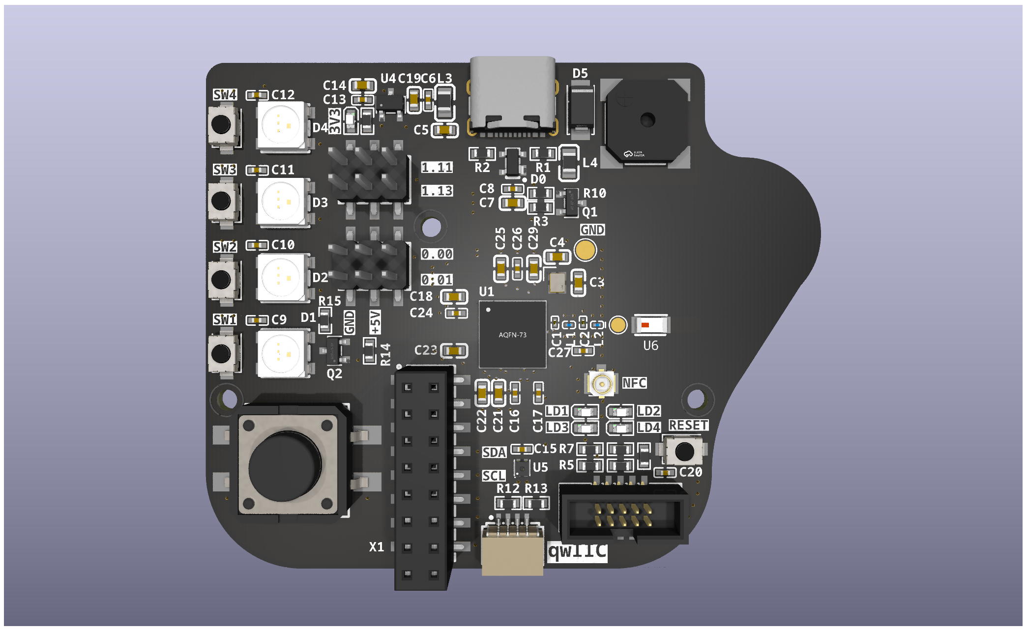
CoffeeCaller. Once a nice office gadget it now evolved to a small development board for the Nordic nRF52840.
Coffeecaller is an open-source printed circuit board by tiacsys, from the tiacsys/ecad-coffeecaller repository on GitHub, published under the CERN-OHL-S-2.0 licence. It is a 2-layer board of 65 × 54 mm with 85 parts on 89 nets, routed with 735 tracks and 133 vias.
It is built around the NRF52840-QIAA-R, SHT40-CD1B-R3 and ANT3216LL00R2400A, with the HYG-8503A-5027, XC6206P332MR and TS-1088R-02026 among its other parts. Its parts include 28 capacitors, 14 resistors, 6 diodes, 5 ICs and 4 inductors. It belongs with the microcontroller boards boards and the nRF52 and nRF5x boards of this library.


This repository holds the KiCad design files for the CoffeeCaller. Once a nice office gadget it now evolved to a small development board for the Nordic nRF52840 featuring buttons, LEDs, buzzer and an onboard temperature sensor.
SoC: Nordic nRF52840
Power
5 V power supply via USB-C connector3.3 V with 200 mAInteractions
Connectivity
5 V, 3.3 V, I2C, SWDPCB
The footprints and symbolds can be imported from EasyEDA's and LCSC's parts database. To do this the tool easyeda2kicad can be used. Please read the instructions on how to setup KiCad to use the new footprint and symbol library provided by easyeda2kicad.
To import all currently in use components just download the closed matching BOM.csv from the releases of this repo and call:
gawk -vFPAT='[^,]*|"[^"]*"' '{print $4}' BOM-coffeecaller.csv | tail -n +2 | xargs -i easyeda2kicad --full --lcsc_id={}This will iterate over the CSV and calls easyeda2kicad to import the component.
To generate your own production files for JLCPCB you can use the kicad-jlcpcb-tools. Installation instructions can be found in the GitHub repo.
| Qty | Value | Footprint | References |
|---|---|---|---|
| 13 | 100nF | easyeda2kicad:C0402 | C6, C8, C9, C10, C11, C12, C13, C15, C16, C17, C20, C24, C26 |
| 12 | 5k1 | easyeda2kicad:R0603 | R1, R2, R5, R6, R7, R8, R9, R10, R11, R12, R13, R14 |
| 5 | 0603White light_C2290 | easyeda2kicad:LED0603-R-RD_WHITE | LD1, LD2, LD3, LD4, LD5 |
| 5 | TS-1088R-02026 | easyeda2kicad:SW-SMD_L3.9-W3.0-P4.45 | RST1, SW1, SW2, SW3, SW4 |
| 4 | 1µF | easyeda2kicad:C0603 | C14, C18, C19, C25 |
| 4 | 4.7µF | easyeda2kicad:C0603 | C7, C21, C22, C23 |
| 4 | WS2812E-V5 | easyeda2kicad:LED-SMD_4P-L5.0-W5.0-LS5.4-TL-1 | D1, D2, D3, D4 |
| 2 | 100R@100MHz | easyeda2kicad:L0805 | L3, L4 |
| 2 | 12pF | easyeda2kicad:C0603 | C3, C4 |
| 2 | 2N7002 | easyeda2kicad:SOT-23-3_L2.9-W1.3-P1.90-LS2.4-BR | Q1, Q2 |
| 2 | 820R | easyeda2kicad:R0603 | R3, R15 |
| 2 | LOGO | LOGO | G***, G*** |
| 2 | PZ254-2-03-S | easyeda2kicad:HDR-SMD_6P-P2.54-V-M-R2-C3-LS7.5-2 | HDR1, HDR2 |
| 1 | 1.0pF | easyeda2kicad:C0201 | C1 |
| 1 | 1.2pF | easyeda2kicad:C0201 | C2 |
| 1 | 100pF | easyeda2kicad:C0603 | C29 |
| 1 | 10nF | easyeda2kicad:C0603 | C5 |
| 1 | 2.2nH | easyeda2kicad:L0201-RD | L2 |
| 1 | 4.7nH | easyeda2kicad:L0201 | L1 |
| 1 | 820pF | easyeda2kicad:C0402 | C27 |
| 1 | ANT3216LL00R2400A | easyeda2kicad:ANT-SMD_L3.2-W1.6 | U6 |
| 1 | HX JN1.27-2X5 TP H4.9 | easyeda2kicad:IDC-SMD_10P-P1.27-3220-10-0300-00 | SWD1 |
| 1 | HYG-8503A-5027 | easyeda2kicad:BUZ-SMD_4P-L8.5-W8.5-P8.50-TL-A | U3 |
| 1 | IPEX-01 | easyeda2kicad:IPEX-SMD_3P-L2.6-W2.6-LS3.0_YUANDI_RF-001 | RF1 |
| 1 | NRF52840-QIAA-R | easyeda2kicad:AQFN-73_L7.0-W7.0-P0.50-BL-EP4.8 | U1 |
| 1 | PM254-2-08-S-8.5 | easyeda2kicad:HDR-SMD_16P-P2.54-V-F-R2-C8-LS7.1 | X1 |
| 1 | PRTR5V0U2X,215 | easyeda2kicad:SOT-143_L2.9-W1.3-P1.92-LS2.3-BR | D0 |
| 1 | Q22FA12800025 | easyeda2kicad:CRYSTAL-SMD_4P-L2.0-W1.6-BL | X2 |
| 1 | SHT40-CD1B-R3 | easyeda2kicad:DFN-4_L1.5-W1.5-P0.80-TL-EP | U5 |
| 1 | SM04B-SRSS-TB (LF)(SN) | easyeda2kicad:CONN-SMD_1.0-4PWT | CN1 |
| 1 | SS210 | easyeda2kicad:SMA_L4.3-W2.6-LS5.2-RD | D5 |
| 1 | TS-1003S-07026 | easyeda2kicad:KEY-SMD_4P-L12.0-W12.0-P5.00-LS15.1 | KEY1 |
| 1 | TYPE-C-31-M-12 | easyeda2kicad:USB-C-SMD_TYPE-C-6PIN-2MD-073 | USBC1 |
| 1 | XC6206P332MR | easyeda2kicad:SOT-23-3_L2.9-W1.6-P1.90-LS2.8-BR | U4 |
The 80 most common of 85 parts.


CoolNamesAllTaken/vibamix
An interactive ePaper nametage for playing "will it blend" with arbitrary groups of people.

Hamza-Anver/OmniStimDriverBoard-PCB
This is an evaluation board to test operating principles of the OptiStim head unit.

Hamza-Anver/OmniStimEvalBoard-Hardware
This is an evaluation board to test operating principles of the OptiStim head unit.

It measures 65 × 54 mm and has 2 copper layers, 1.6 mm thick.
85 parts, built around the NRF52840-QIAA-R, SHT40-CD1B-R3, ANT3216LL00R2400A and HYG-8503A-5027. The full list of its parts is on this page, with links to each part's symbol and footprint where PCBKit's library has them.
From the tiacsys/ecad-coffeecaller repository on GitHub, at the commit this page was made from: the board is coffeecaller.kicad_pcb and its schematic coffeecaller.kicad_sch. PCBKit opens the board in the browser, with nothing to install.
Its repository publishes it under the CERN-OHL-S-2.0 licence: you may reuse it on that licence's terms (keep the author's notice, and for a copyleft licence share your changes alike).