2 layers44.5 × 35.7 mm
 ThunderSloth/walkin-pir-interface
Battery-Powered PIR Motion Interface (Isolated Dry Contact)
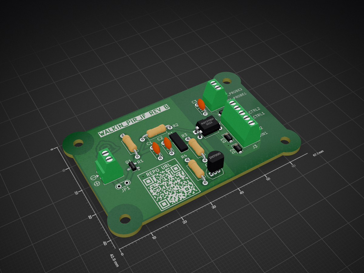
WALKIN PIR IF is an open-source printed circuit board by ThunderSloth, from the ThunderSloth/walkin-pir-interface repository on GitHub, published under the MIT licence. It is a 2-layer board of 64.1 × 40 mm with 24 parts on 13 nets, routed with 66 tracks and 2 vias.
It is built around the AM312, AQY212EH and SMF12CA, with the AO3401A among its other parts. Its parts include 4 resistors, 3 capacitors, 3 diodes, 3 connectors and 2 transistors.


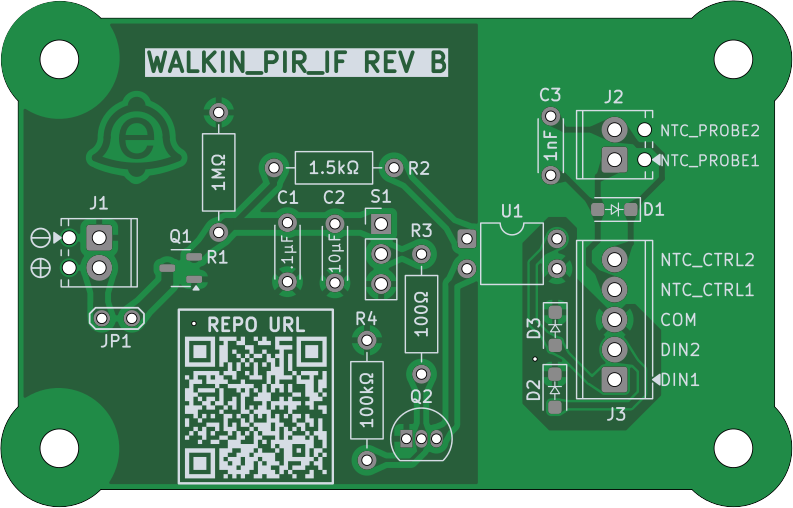
Battery-powered PIR interface designed to trigger motion-activated overhead lighting via an isolated dry input on an XWA11V industrial controller. Intended for installation in a walk-in cooler where running mains power to the sensor is undesirable.
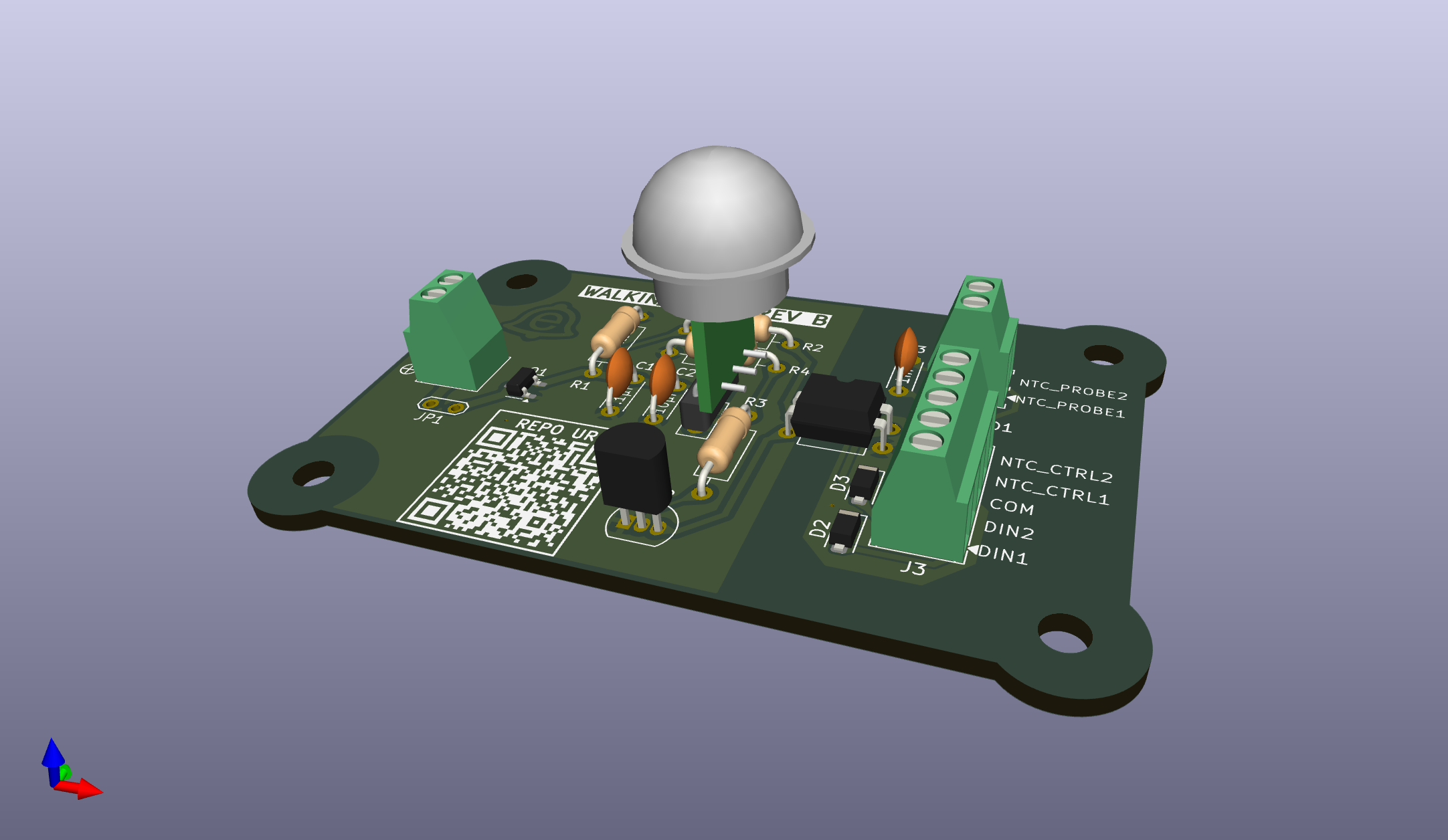
The board detects motion using an AM312 PIR and signals the controller by closing a dry contact (DIN ↔ COM) through a PhotoMOS relay. It also provides a pass-through connection for an external NTC temperature probe, allowing temperature sensing to share the same cable run.
All lighting logic and power switching are handled by the controller; this board functions as a low-power, robust peripheral.
All design, assembly, and fabrication artifacts are published here:
➡️ WALKIN_PIR_IF Documentation (MkDocs)
Rev B sent to fabrication ✅
Simplified prototype validated (video below).
https://github.com/user-attachments/assets/d97296ae-1a20-4d2e-b4a4-3fdf33289da8
| Qty | Value | Footprint | References |
|---|---|---|---|
| 4 | MountingHole | MountingHole:MountingHole_3.2mm_M3 | H1, H2, H3, H4 |
| 3 | SMF12CA | Diode_SMD:D_SOD-123F | D1, D2, D3 |
| 1 | .1µF | Capacitor_THT:C_Disc_D4.3mm_W1.9mm_P5.00mm | C1 |
| 1 | 1.5kΩ | Resistor_THT:R_Axial_DIN0207_L6.3mm_D2.5mm_P10.16mm_Horizontal | R2 |
| 1 | 100kΩ | Resistor_THT:R_Axial_DIN0207_L6.3mm_D2.5mm_P10.16mm_Horizontal | R4 |
| 1 | 100Ω | Resistor_THT:R_Axial_DIN0207_L6.3mm_D2.5mm_P10.16mm_Horizontal | R3 |
| 1 | 10µF | Capacitor_THT:C_Disc_D4.3mm_W1.9mm_P5.00mm | C2 |
| 1 | 1MΩ | Resistor_THT:R_Axial_DIN0207_L6.3mm_D2.5mm_P10.16mm_Horizontal | R1 |
| 1 | 1nF | Capacitor_THT:C_Disc_D4.3mm_W1.9mm_P5.00mm | C3 |
| 1 | 2N7000 | Package_TO_SOT_THT:TO-92_Inline | Q2 |
| 1 | AM312 | Connector_PinHeader_2.54mm:PinHeader_1x03_P2.54mm_Vertical | S1 |
| 1 | AO3401A | Package_TO_SOT_SMD:SOT-23-3 | Q1 |
| 1 | AQY212EH | Package_DIP:DIP-4_W7.62mm | U1 |
| 1 | Battery Terminal | TerminalBlock_Phoenix:TerminalBlock_Phoenix_MPT-0,5-2-2.54_1x02_P2.54mm_Horizontal | J1 |
| 1 | Current Test | TestPoint:TestPoint_2Pads_Pitch2.54mm_Drill0.8mm | JP1 |
| 1 | LOGO | WALKIN_PIR_IF:Repo_URL | G*** |
| 1 | Probe Terminal | TerminalBlock_Phoenix:TerminalBlock_Phoenix_MPT-0,5-2-2.54_1x02_P2.54mm_Horizontal | J2 |
| 1 | XWA11V Terminal | TerminalBlock_Phoenix:TerminalBlock_Phoenix_MPT-0,5-5-2.54_1x05_P2.54mm_Horizontal | J3 |
The 23 most common of 24 parts.
It measures 64.1 × 40 mm and has 2 copper layers, 1.6 mm thick.
24 parts, built around the AM312, AQY212EH, SMF12CA and AO3401A. The full list of its parts is on this page, with links to each part's symbol and footprint where PCBKit's library has them.
From the ThunderSloth/walkin-pir-interface repository on GitHub, at the commit this page was made from: the board is hardware/pcb/kicad/WALKIN_PIR_IF.kicad_pcb and its schematic hardware/pcb/kicad/WALKIN_PIR_IF.kicad_sch. PCBKit opens the board in the browser, with nothing to install.
Its repository publishes it under the MIT licence: you may reuse it on that licence's terms (keep the author's notice, and for a copyleft licence share your changes alike).

abhijithvijayan/wireless-steering-wheel-controls
Wireless steering-wheel audio controls for a car head unit.

donaldbell/productspeedrun
Let's see how quickly we can get a product idea off the ground.


fred314159265/m18-usb-interface
Isolated USB-C adapter for Milwaukee M18 battery diagnostics. KiCad design and v1.0 fab files. Software: m18-protocol-rs.

Stefan1623/VoidLink_Hardware
Four-layer RF PCB design files for a wireless communication system
