2 layers25.4 × 42.9 mm

 fred314159265/m18-usb-interface
Isolated USB-C adapter for Milwaukee M18 battery diagnostics. KiCad design and v1.0 fab files. Software: m18-protocol-rs.
M18-usb interface pcb is an open-source printed circuit board by fred314159265, from the fred314159265/m18-usb-interface repository on GitHub, published under the Unlicense licence. It is a 2-layer board of 33 × 46 mm with 31 parts on 27 nets, routed with 187 tracks and 78 vias.
It is built around the FT234XD-R, LTV-817S and SMF26CA, with the SMF12CA among its other parts. Its parts include 10 resistors, 6 capacitors, 5 diodes, 4 ICs and 2 transistors. It belongs with the power and interfaces and adapters boards of this library.


A USB-C board that plugs into a Milwaukee M18 battery so a PC can talk to the pack's diagnostic pins.
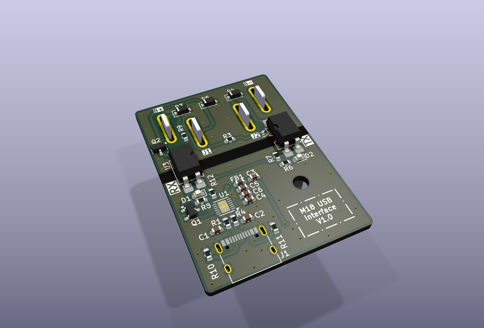
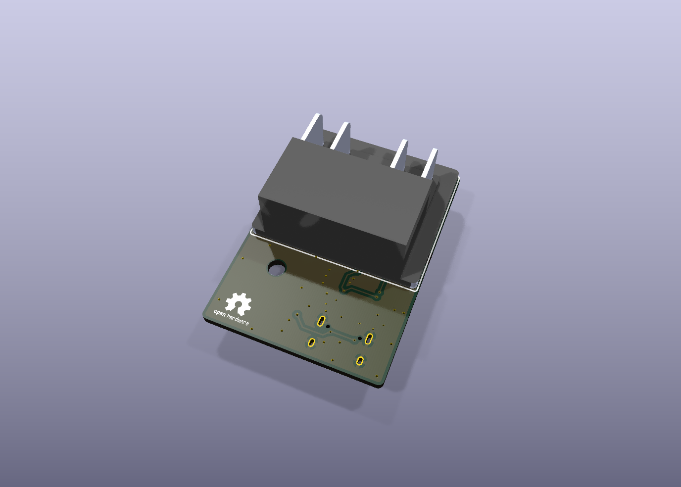
Revision v1.0. The M18 connector is on the back of the board.
Read a health report, cell data, and charge history with m18-protocol-rs:
cargo run --example health_report -- COM3On Linux or macOS, pass the serial device instead, for example /dev/ttyUSB0.
The protocol comes from the reverse engineering in mnh-jansson/m18-protocol. That Python tool works with this board as well.
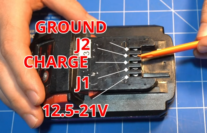
These photos are from the Tool Scientist video and the m18-protocol hardware notes. They show the pack terminals this board connects to.
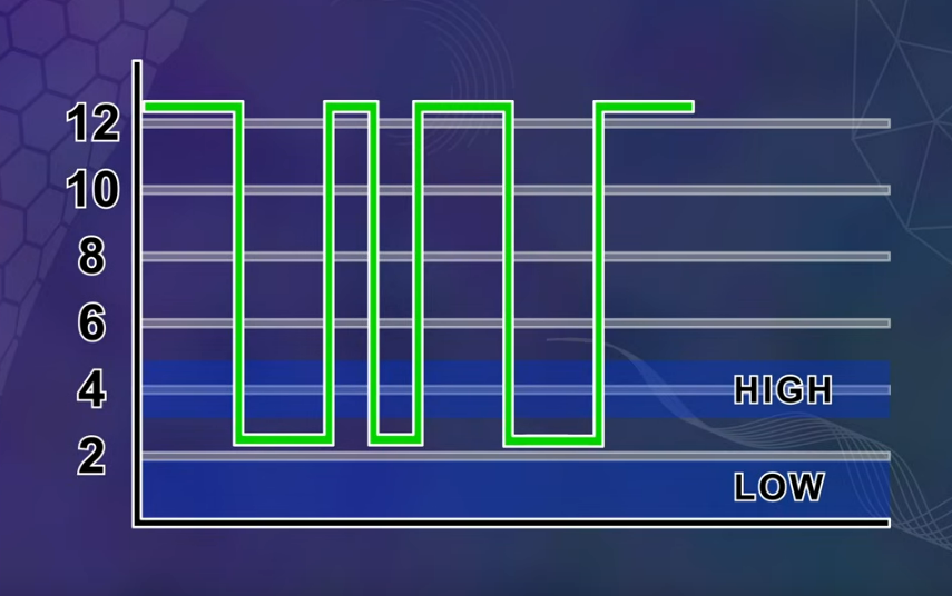
| Pin | Role | Level |
|---|---|---|
| B+ | Pack positive | About 12.5–21 V |
| J1 | Output from the pack | About 3.3–5 V |
| C | Charge terminal | |
| J2 | Input to the pack | About 0–12 V |
| B− | Pack negative |
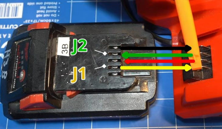
Images/wiring.png is the discrete FTDI adapter and level shifter that this PCB replaces.
The optocouplers invert TX and RX. Program the FT234XD once with FT_Prog, or the link will not decode.
Template: m18-usb-interface-pcb/Releases/v1.0/M18_Interface_FT_Prog_Template.xml
File → Open Template… and select the template.Devices → Scan and Parse.Apply Template, and select the template.Devices → Program.The template writes:
M18 USB InterfaceFabrication files for v1.0:
m18-usb-interface-pcb/Releases/v1.0/production/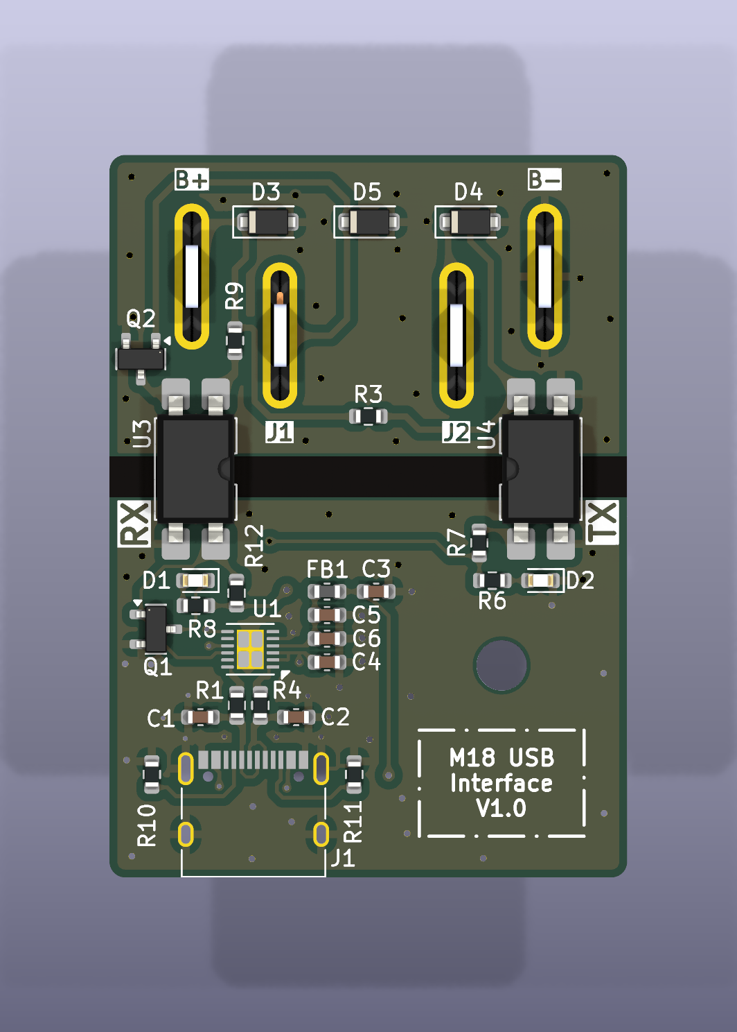
health_report from m18-protocol-rs.This is not a Milwaukee Tool product, and Milwaukee has not endorsed it. Lithium-ion packs can burn if they are shorted or wired wrong. Isolation on this board is not a guarantee if it is assembled incorrectly. Use it at your own risk.
Public domain under The Unlicense.
Tool Scientist and the contributors to m18-protocol documented the pins and the protocol this board is built for.
| Qty | Value | Footprint | References |
|---|---|---|---|
| 4 | 5.1k | Resistor_SMD:R_0603_1608Metric | R9, R10, R11, R12 |
| 3 | 1k | Resistor_SMD:R_0603_1608Metric | R6, R7, R8 |
| 2 | 100nF | Capacitor_SMD:C_0603_1608Metric | C4, C6 |
| 2 | 27R | Resistor_SMD:R_0603_1608Metric | R1, R4 |
| 2 | 2N7002 | Package_TO_SOT_SMD:SOT-23 | Q1, Q2 |
| 2 | 47pF | Capacitor_SMD:C_0603_1608Metric | C1, C2 |
| 2 | LTV-817S | Package_DIP:SMDIP-4_W9.53mm | U3, U4 |
| 2 | SMF26CA | Diode_SMD:D_SOD-123F | D3, D4 |
| 1 | 10nF | Capacitor_SMD:C_0603_1608Metric | C3 |
| 1 | 120Ω@100MHz 2A 50mΩ | Inductor_SMD:L_0603_1608Metric | FB1 |
| 1 | 22kR | Resistor_SMD:R_0603_1608Metric | R3 |
| 1 | 4.7uF | Capacitor_SMD:C_0603_1608Metric | C5 |
| 1 | FT234XD | Package_DFN_QFN:WDFN-12-1EP_3x3mm_P0.45mm_EP1.7x2.5mm | U1 |
| 1 | M18 | M18_USB_Interface:M18_Battery_Interface | U2 |
| 1 | RX | LED_SMD:LED_0603_1608Metric | D1 |
| 1 | SMF12CA | Diode_SMD:D_SOD-123F | D5 |
| 1 | TX | LED_SMD:LED_0603_1608Metric | D2 |
| 1 | USB_C_Receptacle_USB2.0 | Connector_USB:USB_C_Receptacle_XKB_U262-16XN-4BVC11 | J1 |
The 29 most common of 31 parts.
It measures 33 × 46 mm and has 2 copper layers, 1.6 mm thick.
31 parts, built around the FT234XD-R, LTV-817S, SMF26CA and SMF12CA. The full list of its parts is on this page, with links to each part's symbol and footprint where PCBKit's library has them.
From the fred314159265/m18-usb-interface repository on GitHub, at the commit this page was made from: the board is m18-usb-interface-pcb/m18-usb-interface-pcb.kicad_pcb and its schematic m18-usb-interface-pcb/m18-usb-interface-pcb.kicad_sch. PCBKit opens the board in the browser, with nothing to install.
Its repository publishes it under the Unlicense licence: you may reuse it on that licence's terms (keep the author's notice, and for a copyleft licence share your changes alike).


Stefan1623/VoidLink_Hardware
Four-layer RF PCB design files for a wireless communication system

ThunderSloth/walkin-pir-interface
Battery-Powered PIR Motion Interface (Isolated Dry Contact)


gabrielyoung92/gabs_microSMT_PickAndPlace
Independent reorganisation of MicroSMT feeder and PNPv3 files, previews and documentation, with upstream attribution and ChatGPT assistance.

antmicro/scalenode-cm4-baseboard
Baseboard for Raspberry Pi 4 Compute Module optimized for clustering