
2 layers28.3 × 39.8 mm
LevelShifter
gusmanb/logicanalyzer
24 channel, 100Msps logic analyzer hardware and software
21 parts5.1kGPL-3.0
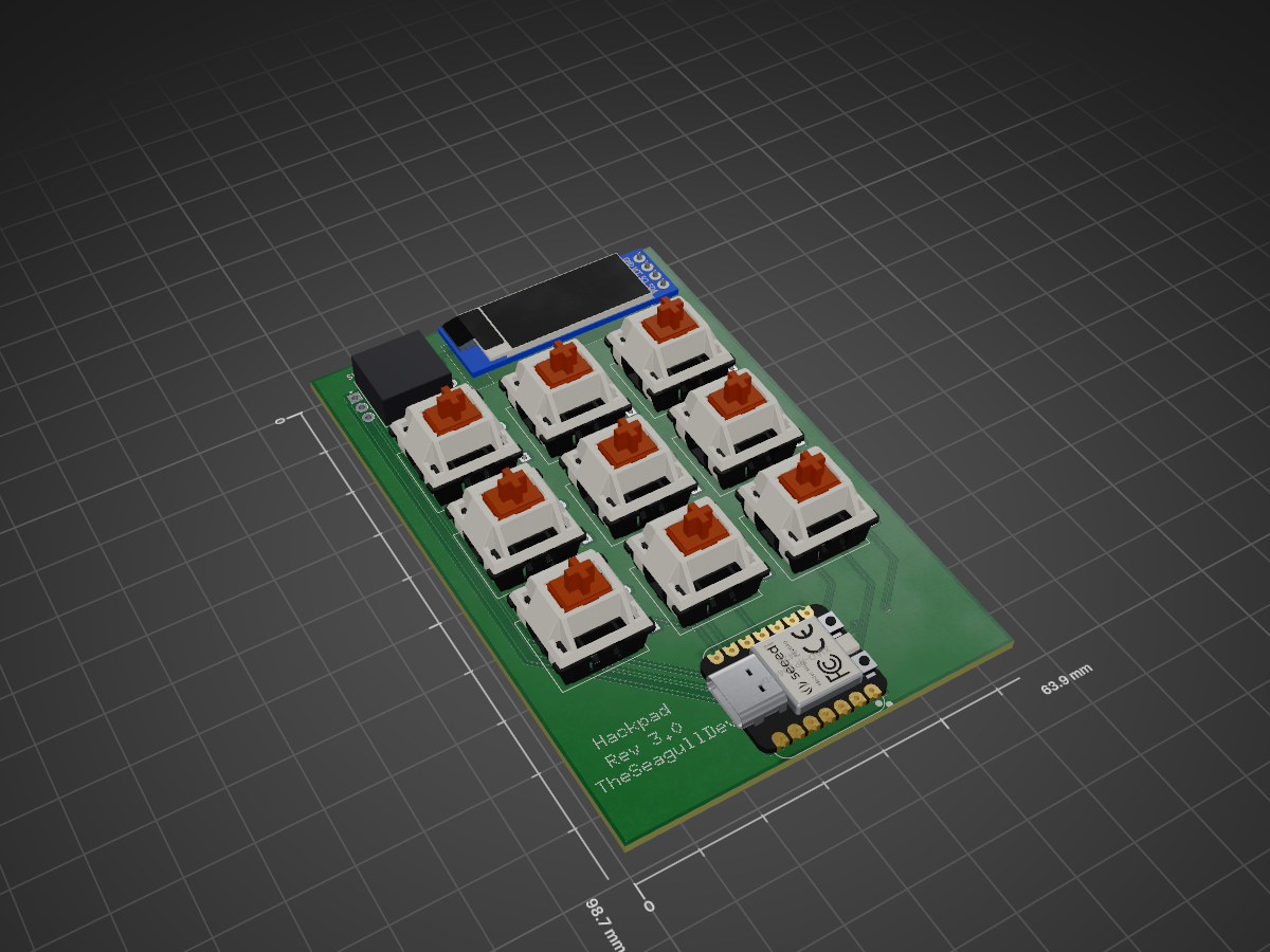
A cool 3x3 macropad I made with an OLED and encoder. I'm going to try to use it as a controller for QLAB and maybe also as a general purpose macropad
Hackpadv2 is an open-source printed circuit board by TheSeagullDev, from the TheSeagullDev/theseagulldevs-ultimate-hackpad repository on GitHub. It is a 2-layer board of 63.9 × 98.7 mm with 21 parts on 23 nets, routed with 86 tracks and 3 vias.
Its parts include 10 switches, 9 diodes, 1 IC and 1 connector. It belongs with the keyboards and input and lEDs and displays boards and the RP2040 boards of this library.
A cool 3x3 macropad I made with an OLED and encoder. I'm going to try to use it as a controller for QLAB and maybe also as a general purpose macropad
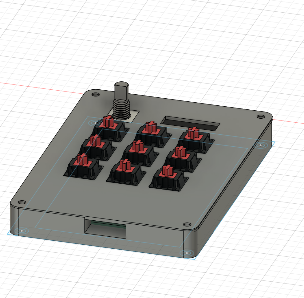
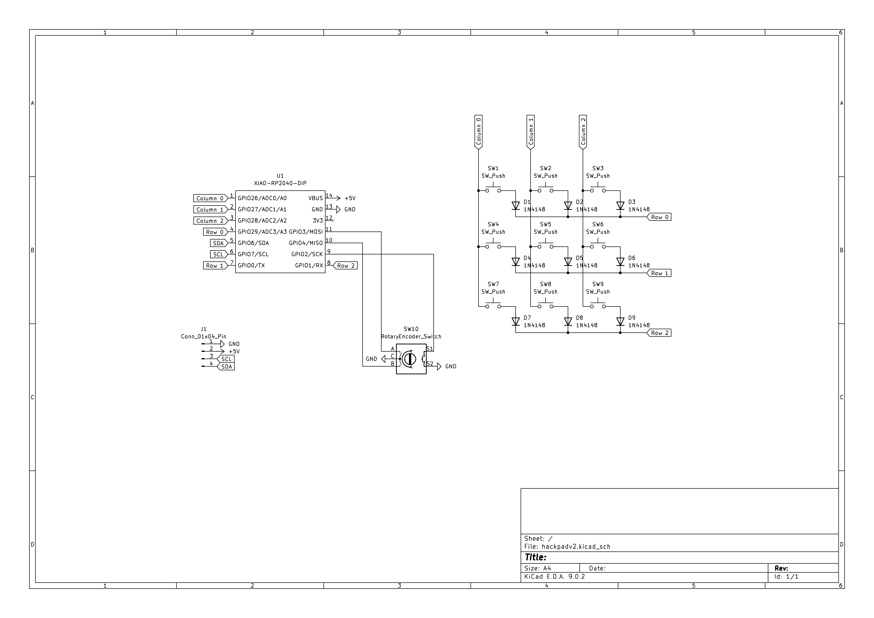
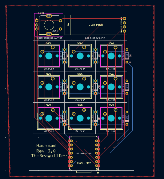
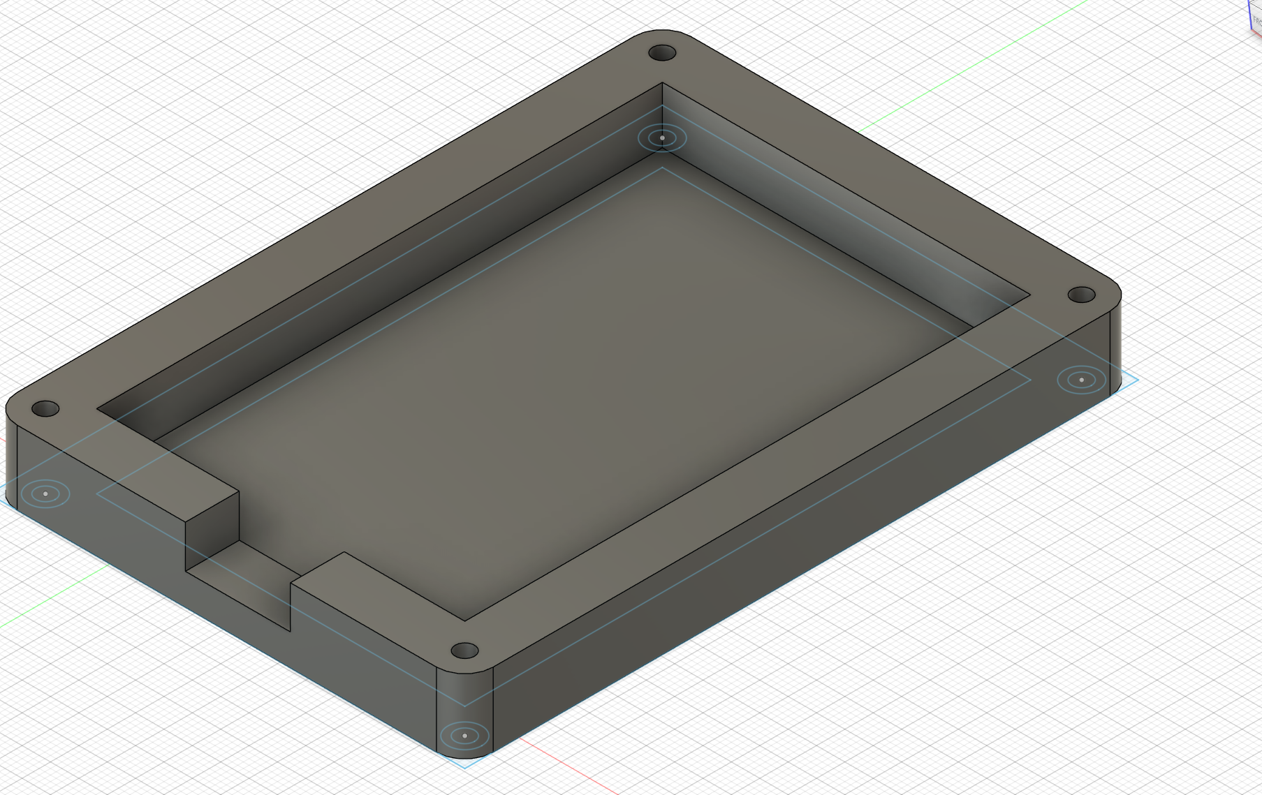
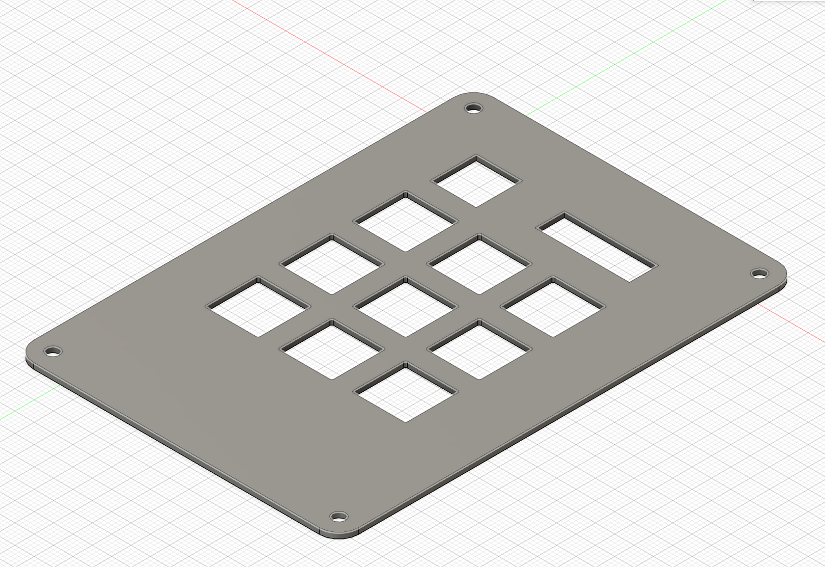
Finished hackpad!
Video (audio ON) https://github.com/user-attachments/assets/ad0931c5-6766-4630-a042-3e10abe5cee0
Building it was definitely a bit of a challenge, as it was my first time soldering and I didn't really know what I was doing. I was ultimately able to get it to work, although I soldered a diode on backwards and I didn't really have any proper equipment to remove the old solder so one diode looks a bit cursed. Other than that my firmware mostly worked with pretty minimal debugging, the only thing that I haven't been able to get working is the encoder button, I think it's because of how I wired it in my schematic. Other than that the only other thing I would've done differently is not put the USB port at the bottom because it's kinda awkward. I learned so much designing and building it and I'm super happy with how it turned out!
| Qty | Value | Footprint | References |
|---|---|---|---|
| 9 | 1N4148 | Diode_THT:D_DO-35_SOD27_P7.62mm_Horizontal | D1, D2, D3, D4, D5, D6, D7, D8, D9 |
| 9 | SW_Push | KeySwitch:SW_Cherry_MX_1.00u_PCB_with_model | SW1, SW2, SW3, SW4, SW5, SW6, SW7, SW8, SW9 |
| 1 | Conn_01x04_Pin | OLED:SSD1306-0.91-OLED-4pin-128x32 | J1 |
| 1 | RotaryEncoder_Switch | Encoder:RotaryEncoder_Alps_EC11E-Switch_Vertical_H20mm | SW10 |
| 1 | XIAO-RP2040-DIP | OPL:XIAO-RP2040-DIP | U1 |
It measures 63.9 × 98.7 mm and has 2 copper layers, 1.6 mm thick.
21 parts. The full list of its parts is on this page, with links to each part's symbol and footprint where PCBKit's library has them.
From the TheSeagullDev/theseagulldevs-ultimate-hackpad repository on GitHub, at the commit this page was made from: the board is PCB/hackpadv2.kicad_pcb and its schematic PCB/Libraries/OPL_Kicad_Library-master/Grove Vision AI V2 Library/Grove - Vision AI Module V2.kicad_sch. PCBKit opens the board in the browser, with nothing to install.
Its repository states no licence, so its author keeps all rights: ask TheSeagullDev before reusing the design.
gusmanb/logicanalyzer
24 channel, 100Msps logic analyzer hardware and software

mntmn/amiga2000-gfxcard
MNT VA2000, an Open Source Amiga 2/3/4000 Graphics Card (Zorro II/III), written in Verilog


hackclub/OnBoard
💡 Join 1,000 teenagers and make your first PCB with a $100 grant!

drandyhaas/KiCadRoutingTools
A set of Python/Rust tools to aid routing in KiCad

Arrow-air/project-quiver
Project Quiver documentation, designs, and project artifacts.

