

4 layers100 × 60 mm
Simple just sensor
williamlin108/USAYPT2026_FlashSensor_MLWGS
10kHz cutoff bandwidth; TO-5 Package Si-photodiode with TIA amplifier (G:2k)
78 parts1

 theo64oliver/smart-scale
Ce projet a ete effectue en groupe de 4 sur une duree de 2 semaines, compose de Antoine JOUY, Alexis VASSEUR, Benjamin BOYER et Theo OLIVER.
PCB design group7 is an open-source printed circuit board by theo64oliver, from the theo64oliver/smart-scale repository on GitHub. It is a 2-layer board of 70 × 70 mm with 26 parts on 52 nets, routed with 134 tracks and 0 vias.
It is built around the ESP32-DEVKITC-VE and OP1177AR. Its parts include 7 resistors, 6 capacitors, 4 ICs, 4 diodes and 2 switches. It belongs with the ESP32 boards of this library.
Ce projet a ete effectue en groupe de 4 sur une duree de 2 semaines, compose de Antoine JOUY, Alexis VASSEUR, Benjamin BOYER et Theo OLIVER.
Utilisation de la loi d’Ohm :
$$ V = R \times I \Rightarrow R = \frac{V}{I} = \frac{5}{0{,}015} = 333\ \Omega $$
Résistance à ajouter pour le buzzer : 333 Ω
Choix pratique : résistance normalisée de 330 Ω
Calcul de la puissance :
$$ P = I^2 \times R = (0{,}015)^2 \times 330 = 0.07425,W $$
Dissipation thermique : environ 74,2 mW
Calcul du courant :
$$ I = \frac{V}{R} = \frac{3{,}3}{10000} = 0{,}00033,A = 0{,}33,mA $$
Calcul de la puissance :
$$ P = I^2 \times R = (0{,}00033)^2 \times 10000 = 0{,}001089,W $$
Dissipation thermique : environ 1,1 mW
Objectif : obtenir une constante de temps $\tau$ d’environ 6,67 ms (20 ms ÷ 3)
$$ C = \frac{\tau}{R} = \frac{0{,}00667}{10000} = 667 \times 10^{-9},F = 667,nF $$
Valeur normalisée à utiliser : 680 nF
Calcul de la tension aux bornes de la résistance :
$$ V_R = V_{GPIO} - V_{LED} = 3{,}3 - 2{,}0 = 1{,}3,V $$
Calcul de la résistance :
$$ R = \frac{V_R}{I} = \frac{1{,}3}{0{,}015} ≈ 87,\Omega $$
Choix pratique : résistance normalisée de 100 Ω pour réduire le courant.
Avec R = 100 Ω et I = 15 mA :
$$ P = I^2 \times R = (0{,}015)^2 \times 100 = 0{,}000225 \times 100 = 0{,}0225,W = 22{,}5,mW $$
Dissipation thermique : environ 22,5 mW (très faible, standard acceptable)
Utilisation de 2 condensateurs céramiques recommandée avec le régulateur 7805 :
Source : Analyse du 7805
Nous avons choisi de ne pas inclure d’emplacements pour le capteur de pression et l’écran LCD sur le PCB. Cette décision a été motivée par la volonté de réduire au maximum la surface du circuit imprimé, afin de limiter les coûts de fabrication.
Voici notre vision de la balance :
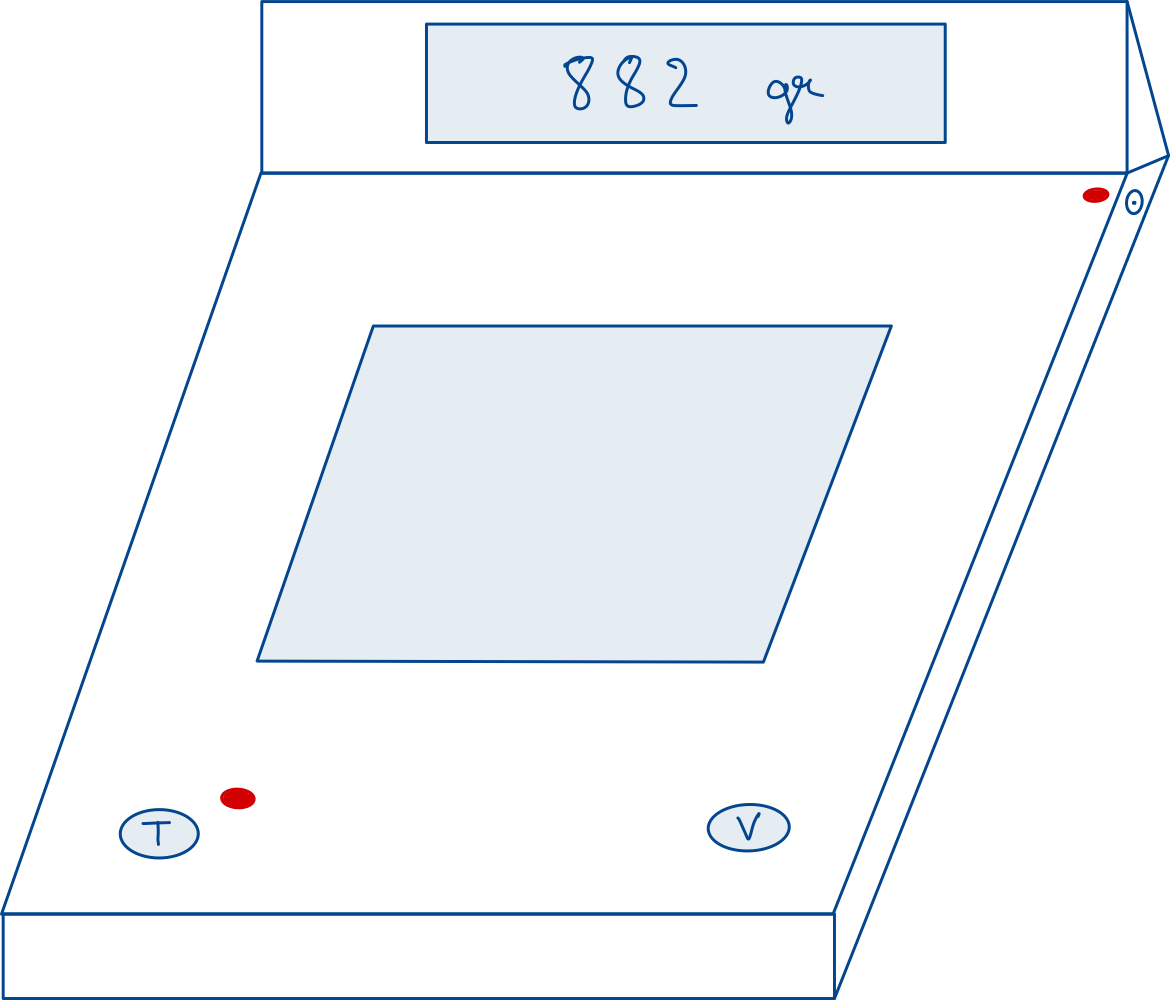
Concernant la LED d’alimentation, nous avons opté pour une implémentation matérielle simple. Le détail de ce choix est visible dans le schéma d’alimentation.
La nomenclature des composants (BOM) est disponible dans l’archive ZIP fournie. Nous avons volontairement choisi de ne pas indiquer les prix exacts, car ceux-ci peuvent varier entre le moment de la rédaction et l’achat effectif des composants.
Lors de la conception du PCB, nous avons pris soin de consulter le rapport DRC (Design Rule Check) afin de nous assurer qu’aucune erreur de routage n’était présente. Le résultat final ne présente aucune erreur : le PCB est conforme aux règles de conception.
| Qty | Value | Footprint | References |
|---|---|---|---|
| 2 | 100nF | Capacitor_THT:CP_Radial_D4.0mm_P1.50mm | C5, C6 |
| 2 | 10kΩ | Resistor_THT:R_Axial_DIN0204_L3.6mm_D1.6mm_P7.62mm_Horizontal | R1, R2 |
| 2 | 10µF | Capacitor_THT:CP_Radial_D4.0mm_P1.50mm | C4, C9 |
| 2 | 220Ω | Resistor_THT:R_Axial_DIN0204_L3.6mm_D1.6mm_P7.62mm_Horizontal | R3, R5 |
| 2 | 330Ω | Resistor_THT:R_Axial_DIN0204_L3.6mm_D1.6mm_P7.62mm_Horizontal | R2, R5 |
| 2 | 680nF | Capacitor_THT:CP_Radial_D4.0mm_P1.50mm | C1, C1 |
| 2 | D | Diode_THT:D_5W_P10.16mm_Horizontal | D1, D2 |
| 2 | LED | LED_THT:LED_D5.0mm | D3, D4 |
| 2 | SW_Push | Button_Switch_THT:SW_PUSH-12mm | SW1, SW2 |
| 1 | Barrel_Jack_Switch_Pin3Ring | Connector_BarrelJack:BarrelJack_CUI_PJ-036AH-SMT_Horizontal | J1 |
| 1 | Battery | Connector_PinSocket_2.00mm:PinSocket_1x02_P2.00mm_Vertical | BT1 |
| 1 | Buzzer | Buzzer_Beeper:Buzzer_TDK_PS1240P02BT_D12.2mm_H6.5mm | BZ1 |
| 1 | ESP32-DevKitC | PCM_Espressif:ESP32-DevKitC | U1 |
| 1 | LCD-016N002L | Connector_PinSocket_2.00mm:PinSocket_1x04_P2.00mm_Vertical | U2 |
| 1 | LM7805_TO220 | Package_TO_SOT_THT:TO-220-3_Horizontal_TabDown | U3 |
| 1 | OP1177AR | Package_SO:SOIC-8_3.9x4.9mm_P1.27mm | U4 |
| 1 | X | Connector_PinSocket_2.00mm:PinSocket_1x02_P2.00mm_Vertical | R6 |
It measures 70 × 70 mm and has 2 copper layers, 1.6 mm thick.
26 parts, built around the ESP32-DEVKITC-VE and OP1177AR. The full list of its parts is on this page, with links to each part's symbol and footprint where PCBKit's library has them.
From the theo64oliver/smart-scale repository on GitHub, at the commit this page was made from: the board is PCB_design_group7.kicad_pcb and its schematic PCB_design_group7.kicad_sch. PCBKit opens the board in the browser, with nothing to install.
Its repository states no licence, so its author keeps all rights: ask theo64oliver before reusing the design.
williamlin108/USAYPT2026_FlashSensor_MLWGS
10kHz cutoff bandwidth; TO-5 Package Si-photodiode with TIA amplifier (G:2k)

akshmakov/utcs-isource
micro-transcranial current stimulation system - constant current source module


harbaum/galagino
A Galaga, Pac-Man and Donkey Kong arcade emulator for the ESP32

RParkerE/OpenSilicon
OpenSilicon enables DIY semiconductor fabrication with open-source guides for building IC equipment at home. The project includes BOMs, 3D files, firmware, and PDKs, supporting makers and researchers in chip fabrication.

cole8888/SRNE-Solar-Charge-Controller-Monitor
Read data from SRNE solar charge controllers.
